Gigabyte GA-P55-UD3L Manual
Gigabyte GA-P55-UD3L Manual
 |
UPC - 818313009050
View all Gigabyte GA-P55-UD3L manuals
Add to My Manuals
Save this manual to your list of manuals |
Gigabyte GA-P55-UD3L manual content summary:
- Gigabyte GA-P55-UD3L | Manual - Page 1
GA-P55-UD3L-TPM/ GA-P55-UD3L/ GA-P55-US3L LGA1156 socket motherboard for Intel® Core™ i7 processor family/ Intel® Core™ i5 processor family User's Manual Rev. 1002 12ME-P55UD3L-1002R - Gigabyte GA-P55-UD3L | Manual - Page 2
Motherboard GA-P55-UD3L/GA-P55-US3L Aug. 3, 2009 Motherboard GA-P55-UD3L / GA-P55-US3L Aug. 3, 2009 - Gigabyte GA-P55-UD3L | Manual - Page 3
Motherboard GA-P55-UD3L-TPM Oct. 5, 2009 Motherboard GA-P55-UD3L-TPM Oct. 5, 2009 - Gigabyte GA-P55-UD3L | Manual - Page 4
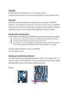
the product. For detailed product information, carefully read the User's Manual. For instructions on how to use GIGABYTE's unique features, read or download the information on/from the Support&Downloads\Motherboard\Technology Guide page on our website. For product-related information, check on our - Gigabyte GA-P55-UD3L | Manual - Page 5
TPM/GA-P55-UD3L/GA-P55-US3L Motherboard Layout 8 Block Diagram...9 Chapter 1 Hardware Installation 11 1-1 Installation Precautions 11 1-2 Product Specifications 12 1-3 Installing the CPU and CPU Cooler 15 1-3-1 Installing the CPU 15 1-3-2 Installing the CPU Cooler 17 1-4 Installing the Memory - Gigabyte GA-P55-UD3L | Manual - Page 6
6™ ...78 4-7 Smart TPM j 81 4-8 Auto Green...82 4-9 eXtreme Hard Drive (X.H.D 83 Chapter 5 Appendix...85 5-1 Configuring SATA Hard Drive(s 85 5-1-1 Configuring Intel P55 SATA Controllers 85 5-1-2 Configuring GIGABYTE SATA2 SATA Controller 93 5-1-3 Making a SATA RAID/AHCI Driver Diskette 99 - Gigabyte GA-P55-UD3L | Manual - Page 7
GA-P55-UD3L-TPM, GA-P55-UD3L, or GA-P55-US3L motherboard Motherboard driver disk User's Manual Quick Installation Guide motherboard image is for reference only. Optional Items Floppy disk drive cable (Part No. 12CF1-1FD001-7*R) 2-port USB 2.0 bracket (Part No. 12CR1-1UB030-5*R) 2-port SATA power - Gigabyte GA-P55-UD3L | Manual - Page 8
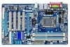
-P55-UD3L-TPM/GA-P55-UD3L/GA-P55-US3L Motherboard Layout KB_USB ATX_12V GA-P55-UD3L-TPM/ GA-P55-UD3L / GA-P55-US3L PHASE LED LGA1156 PWR_FAN COAXIAL COMA LPT R_USB ATX USB_LAN AUDIO F_AUDIO SYS_FAN1 PCIEX1 (Note) BAT CPU_FAN DDR3_2 DDR3_1 DDR3_4 DDR3_3 RTL8111D CODEC SPDIF_O CD_IN TPM - Gigabyte GA-P55-UD3L | Manual - Page 9
Intel® P55 x4 PCI Express Bus Dual BIOS 6 SATA 3Gb/s 14 USB Ports CODEC LPC Bus IT8720 Floppy COM Port PS/2 KB/Mouse TPM j MIC (Center/Subwoofer Speaker Out) Line-Out (Front Speaker Out) Line-In (Rear Speaker Out) S/PDIF In S/PDIF Out 4 PCI PCI CLK (33 MHz) j Only for GA-P55-UD3L-TPM. - 9 - - Gigabyte GA-P55-UD3L | Manual - Page 10
- 10 - - Gigabyte GA-P55-UD3L | Manual - Page 11
or memory. If you do not have an ESD wrist strap, keep your hands dry and first touch a metal object to eliminate static electricity. • Prior to installing the motherboard, please have it on top of an antistatic pad or within an electrostatic shielding container. • Before unplugging the power supply - Gigabyte GA-P55-UD3L | Manual - Page 12
1-2 Product Specifications CPU Support for an Intel® Core™ i7 series processor/Intel® Core™ i5 series processor in the LGA1156 package (Go to GIGABYTE's website for the latest CPU support list.) L3 cache varies with CPU Chipset Intel® P55 Express Chipset Memory Audio 4 x - Gigabyte GA-P55-UD3L | Manual - Page 13
System voltage detection CPU/System temperature detection CPU/System/Power fan speed detection CPU overheating warning CPU/System/Power fan fail warning CPU/System fan speed control (Note 5) 2 x 16 Mbit flash Use of licensed AWARD BIOS Support for DualBIOS™ PnP 1.0a, DMI 2.0, SM BIOS 2.4, ACPI 1.0b - Gigabyte GA-P55-UD3L | Manual - Page 14
Operating System w Support for Microsoft® Windows® 7/Vista/XP Form Factor w ATX Form Factor; 30.5cm x 19.0cm j Only for GA-P55-UD3L-TPM. (Note 1) Due to Windows Vista/XP 32-bit operating system limitation, when more than 4 GB of physical memory is installed, the actual memory size displayed - Gigabyte GA-P55-UD3L | Manual - Page 15
before you begin to install the CPU: • Make sure that the motherboard supports the CPU. (Go to GIGABYTE's website for the latest CPU support list.) • Always turn off the computer and unplug the power cord from the power outlet before installing the CPU to prevent hardware damage. • Locate the - Gigabyte GA-P55-UD3L | Manual - Page 16
B. Follow the steps below to correctly install the CPU into the motherboard CPU socket. Before installing the CPU, make sure to turn off the computer and unplug the power cord from the power outlet to prevent damage to the CPU. Step 1: Gently press the CPU socket lever handle down and away from the - Gigabyte GA-P55-UD3L | Manual - Page 17
installation manual for instructions on installing the cooler.) Step 5: After the installation, check the back of the motherboard. If the push pin is inserted as the picture above shows, the installation is complete. Step 6: Finally, attach the power connector of the CPU cooler to the CPU fan - Gigabyte GA-P55-UD3L | Manual - Page 18
Make sure that the motherboard supports the memory. It is recommended that memory of the same capacity, brand, speed, and chips be used. (Go to GIGABYTE's website for the latest memory support list.) • Always turn off the computer and unplug the power cord from the power outlet before installing the - Gigabyte GA-P55-UD3L | Manual - Page 19
to turn off the computer and unplug the power cord from the power outlet to prevent damage to the memory module. DDR3 and DDR2 DIMMs are not compatible to each other or DDR DIMMs. Be sure to install DDR3 DIMMs on this motherboard. Notch DDR3 DIMM A DDR3 memory module has a notch, so it can only fit - Gigabyte GA-P55-UD3L | Manual - Page 20
motherboard supports the expansion card. Carefully read the manual that came with your expansion card. • Always turn off the computer and unplug the power cord from the power , go to BIOS Setup to make any required BIOS changes for your expansion card(s). 7. Install the driver provided with the - Gigabyte GA-P55-UD3L | Manual - Page 21
using this feature, ensure that your audio system provides a coaxial digital audio in connector. RJ-45 LAN Port The Gigabit Ethernet LAN port provides Internet connection at up to 1 Gbps data rate. The following describes the states of the LAN port LEDs. Connection/ Speed LED Activity LED LAN Port - Gigabyte GA-P55-UD3L | Manual - Page 22
need connect with the port of HD Audio standard via front panel and enable the multi-channel audio feature through the audio driver. Refer to the instructions on setting up a 2/4/5.1/7.1-channel audio configuration in Chapter 5, "Configuring 2/4/5.1/7.1-Channel Audio." Hardware Installation - 22 - Gigabyte GA-P55-UD3L | Manual - Page 23
with the connectors you wish to connect. • Before installing the devices, be sure to turn off the devices and your computer. Unplug the power cord from the power outlet to prevent damage to the devices. • After installing the device and before turning on the computer, make sure the device cable has - Gigabyte GA-P55-UD3L | Manual - Page 24
an unstable or unbootable system. • The main power connector is compatible with power supplies with 2x10 power connectors. When using a 2x12 power supply, remove the protective cover from the main power connector on the motherboard. Do not insert the power supply cable into pins under the protective - Gigabyte GA-P55-UD3L | Manual - Page 25
3-pin power fan header (PWR_FAN). Most fan headers possess a foolproof insertion design. When connecting a fan cable, be sure to connect it in the correct orientation (the black connector wire is the ground wire). The motherboard supports CPU fan speed control, which requires the use of a CPU fan - Gigabyte GA-P55-UD3L | Manual - Page 26
3Gb/s standard and are compatible with SATA 1.5Gb/s standard. Each SATA connector supports a single SATA device. The P55 Chipset supports RAID 0, RAID 1, RAID 5, and RAID 10. Refer to Chapter 5, "Configuring SATA Hard Drive(s)," for instructions on configuring a RAID array. 7 1 SATA2_0 Pin No - Gigabyte GA-P55-UD3L | Manual - Page 27
compatible with SATA 1.5Gb/s standard. Each SATA connector supports a single SATA device. The GIGABYTE SATA2 controller supports RAID 0, RAID 1, and JBOD. Refer to Chapter 5, "Configuring SATA Hard Drive(s)," for instructions on configuring a RAID computer and unplug the power cord. 2. Gently remove - Gigabyte GA-P55-UD3L | Manual - Page 28
beep will be heard if no problem is detected at system startup. If a problem is detected, the BIOS may issue beeps in different patterns to indicate the problem. Refer to Chapter 5, "Troubleshooting," for information about beep codes. • HD (Hard Drive Activity LED, Blue) Connects to the hard drive - Gigabyte GA-P55-UD3L | Manual - Page 29
MIC Power 4 -ACZ_DET 4 NC 5 LINE2_R 5 Line Out (R) 6 GND 6 NC 7 FAUDIO_JD 7 NC 8 No Pin 8 No Pin 9 LINE2_L 9 Line Out (L) 10 GND 10 NC • The front panel audio header supports HD audio by default. If your chassis provides an AC'97 front panel audio module, refer to the instructions on - Gigabyte GA-P55-UD3L | Manual - Page 30
Power 1 2 SPDIFI 3 GND 15) SPDIF_O (S/PDIF Out Header) This header supports digital S/PDIF Out and connects a S/PDIF digital audio cable (provided by expansion cards) for digital audio output from your motherboard carefully read the manual for your expansion card. 1 Pin No. Definition 1 - Gigabyte GA-P55-UD3L | Manual - Page 31
the jumper. Failure to do so may cause damage to the motherboard. • After system restart, go to BIOS Setup to load factory defaults (select Load Optimized Defaults) or manually configure the BIOS settings (refer to Chapter 2, "BIOS Setup," for BIOS configurations). - 31 - Hardware Installation - Gigabyte GA-P55-UD3L | Manual - Page 32
18) PHASE LED The number of lighted LEDs indicates the CPU loading. The higher the CPU loading, the more the number of lighted LEDs. To enable the Phase LED display function, please first enable Dynamic Energy Saver™ 2. Refer to Chapter 4, "Dynamic Energy Saver™ 2," for more details. Hardware - Gigabyte GA-P55-UD3L | Manual - Page 33
that searches and downloads the latest version of BIOS from the Internet and updates the BIOS. For instructions on using the Q-Flash and @BIOS utilities, refer to Chapter 4, "BIOS Update Utilities." • Because BIOS flashing is potentially risky, if you do not encounter problems using the current - Gigabyte GA-P55-UD3L | Manual - Page 34
v6.00PG, An Energy Star Ally Copyright (C) 1984-2009, Award Software, Inc. Motherboard Model BIOS Version P55-UD3L D11 . . . . : BIOS Setup : XpressRecovery2 : Boot Menu : Qflash 07/17/2009-P55-7A89RG0LC-00 Function Keys Function Keys Function Keys: : POST SCREEN Press - Gigabyte GA-P55-UD3L | Manual - Page 35
to accept or enter a sub-menu. (Sample BIOS Version: GA-P55-UD3L D11) CMOS Setup Utility-Copyright (C) 1984-2009 Award Software MB Intelligent Tweaker(M.I.T.) Standard CMOS Features Advanced BIOS Features Integrated Peripherals Power Management Setup PC Health Status Load Fail-Safe - Gigabyte GA-P55-UD3L | Manual - Page 36
Abandon all changes and the previous settings remain in effect. Pressing to the confirmation message will exit BIOS Setup. (Pressing can also carry out this task.) Security Chip Configuration j Use this menu to configure the TPM function. j Only for GA-P55-UD3L-TPM. BIOS Setup - 36 - - Gigabyte GA-P55-UD3L | Manual - Page 37
overclock/overvoltage may result in damage to CPU, chipset, or memory CPU that supports this feature. For more information about Intel CPUs' unique features, please visit Intel's website. (Note 2) This item appears only if you install a memory module that supports this feature. - 37 - BIOS - Gigabyte GA-P55-UD3L | Manual - Page 38
frequency and voltage will be reduced during system halt state to decrease power consumption. Auto lets the BIOS automatically configure this setting. (Default: Auto) (Note) This item is present only if you install a CPU that supports this feature. For more information about Intel CPUs' unique - Gigabyte GA-P55-UD3L | Manual - Page 39
This value is determined by multiplying the BLCK Frequency value by the Uncore Clock Ratio value. (Note) This item is present only if you install a CPU that supports this feature. For more information about Intel CPUs' unique features, please visit Intel's website. - 39 - BIOS Setup - Gigabyte GA-P55-UD3L | Manual - Page 40
first verify the overclocking capability of your CPU. As stability is highly dependent on system components, when system instability occurs after overclocking, lower the overclocking ratio. (Note) This item appears only if you install a memory module that supports this feature. BIOS Setup - 40 - Gigabyte GA-P55-UD3L | Manual - Page 41
operating frequency of the memory being used; the second is the memory frequency that is automatically adjusted according to the BCLK Frequency(Mhz) and System Memory Multiplier settings. (Note) This item appears only if you install a memory module that supports this feature. - 41 - BIOS Setup - Gigabyte GA-P55-UD3L | Manual - Page 42
memory module or Extreme Memory Profile (X.M.P.) is set to Disabled, this item will display as 1.5V. When Extreme Memory memory. Profile QPI Voltage The value displayed here is dependent on the CPU 1 >>>>> Channel A Misc Timing Control x B2B CAS Delay - x Timing Control CAS Latency Time Options are - Gigabyte GA-P55-UD3L | Manual - Page 43
tRAS Options are: Auto (default), 1~31. >>>>> Channel A/B Advanced Timing Control tRC Options are: Auto (default), 1~63. tRRD Options are: Auto Rate(CMD) Options are: Auto (default), 1~3. >>>>> Channel A/B Misc Timing Control B2B CAS Delay Options are: Auto (default), 1~31. Round Trip Latency Options - Gigabyte GA-P55-UD3L | Manual - Page 44
are: Auto (default), 1~8. Different Ranks Options are: Auto (default), 1~8. On The Same Rank Options are: Auto (default), 1~2. ESC: Exit F1: General Help F7: Optimized Defaults BIOS Setup - 44 - - Gigabyte GA-P55-UD3L | Manual - Page 45
Mother Board Voltage Control ****** Voltage Types Normal Current >>> CPU Load-Line Calibration [Disabled] CPU Vcore 1.11250V feature adjusts Vdroop, keeping the CPU voltage more constant under light and heavy CPU load. Disabled sets the CPU voltage following Intel specifications - Gigabyte GA-P55-UD3L | Manual - Page 46
Help F7: Optimized Defaults Isochronous Support Determines whether to enable specific streams within the CPU and Chipset. (Default: Enabled) CMOS Press Enter] Item Help Menu Level BIOS Version BCLK CPU Frequency Memory Frequency Total Memory Size D11 133.27 MHz 3198.42 - Gigabyte GA-P55-UD3L | Manual - Page 47
F7: Optimized Defaults CMOS Setup Utility-Copyright (C) 1984-2009 Award Software Standard CMOS Features Extended Memory Total Memory 1022M 1024M Item Help Menu Level Move Enter: Select F5: Previous Values IDE/SATA devices by using one of the three methods below: - 47 - BIOS Setup - Gigabyte GA-P55-UD3L | Manual - Page 48
during the POST for faster system startup. • Manual Allows you to manually enter the specifications of the hard drive when the hard drive other errors. Memory These fields are read-only and are determined by the BIOS POST. Base Memory Also called conventional memory. Typically, 640 - Gigabyte GA-P55-UD3L | Manual - Page 49
the minus key (or ) to move it up or down on the list. Press to exit this menu when finished. Quick Boot Enables or disables the you install a CPU that supports this feature. For more information about Intel CPUs' unique features, please visit Intel's website. - 49 - BIOS Setup - Gigabyte GA-P55-UD3L | Manual - Page 50
for Windows XP operating system; set this item to Enabled for legacy operating system such as Windows NT4.0. (Default: Disabled) No-Execute Memory you install a CPU that supports this feature. For more information about Intel CPUs' unique features, please visit Intel's website. BIOS Setup - 50 - - Gigabyte GA-P55-UD3L | Manual - Page 51
the SATA controllers to AHCI mode. Advanced Host Controller Interface (AHCI) is an interface specification that allows the storage driver to enable advanced Serial ATA features such as Native Command Queuing and hot plug. SATA Port0-3 Native Mode (Intel P55 Chipset) Specifies the - Gigabyte GA-P55-UD3L | Manual - Page 52
to install a 3rd party add-in network card instead of using the onboard LAN, the corresponding LAN controller will be disabled motherboard incorporates cable diagnostic feature designed to detect the status of the attached LAN cable. This feature Windows mode or when the LAN Boot ROM is activated - Gigabyte GA-P55-UD3L | Manual - Page 53
SATA controller to AHCI mode. Advanced Host Controller Interface (AHCI) is an interface specification that allows the storage driver to enable advanced Serial ATA features such as Native Command Queuing and hot plug. RAID/IDE Enables RAID for the SATA controller; the IDE controller still - Gigabyte GA-P55-UD3L | Manual - Page 54
ATX power supply providing at least 1A on the +5VSB lead. (Default: Enabled) Power On by Ring Allows the system to be awakened from an ACPI sleep state by a wake-up signal from a modem that supports wake-up function. (Default: Enabled) (Note) Supported on Windows Vista operating system only. BIOS - Gigabyte GA-P55-UD3L | Manual - Page 55
The system stays off upon the return of the AC power. (Default) Full-On The system is turned on upon the return of the AC power. Memory The system returns to its last known awake state upon the return of the AC power. (Note) Supported on Windows Vista operating system only. - 55 - BIOS Setup - Gigabyte GA-P55-UD3L | Manual - Page 56
POWER FAN Speed Current SYSTEM FAN1 Speed CPU Warning Temperature CPU FAN Fail Warning SYSTEM FAN2 Fail Warning POWER FAN Fail Warning SYSTEM FAN1 Fail Warning CPU Smart FAN Control CPU chassis intrusion detection device attached to the motherboard CI header. If the system chassis - Gigabyte GA-P55-UD3L | Manual - Page 57
Mode Specifies how to control CPU fan speed. This item is configurable only if CPU Smart FAN Control is set to Enabled. Auto Lets the BIOS automatically detect the type of CPU fan installed and sets the optimal CPU fan control mode. (Default) Voltage Sets Voltage mode for a 3-pin CPU fan. PWM - Gigabyte GA-P55-UD3L | Manual - Page 58
> on this item and then press the key to load the optimal BIOS default settings. The BIOS defaults settings help the system to operate in optimum state. Always load the Optimized defaults after updating the BIOS or after clearing the CMOS values. j Only for GA-P55-UD3L-TPM. BIOS Setup - 58 - - Gigabyte GA-P55-UD3L | Manual - Page 59
the BIOS settings but not to make changes. To clear the password, press on the password item and when requested for the password, press again. The message "PASSWORD DISABLED" will appear, indicating the password has been cancelled. j Only for GA-P55-UD3L-TPM. - 59 - BIOS Setup - Gigabyte GA-P55-UD3L | Manual - Page 60
all Data F11: Save CMOS to BIOS F12: Load CMOS from BIOS Press on this item and press the key. This exits the BIOS Setup without saving the changes made in BIOS Setup to the CMOS. Press or to return to the BIOS Setup Main Menu. j Only for GA-P55-UD3L-TPM. BIOS Setup - 60 - - Gigabyte GA-P55-UD3L | Manual - Page 61
chip and initializes the Security Platform. Disabled Disables the security chip. (Default) Security Chip State Displays the current settings in the security chip. j Only for GA-P55-UD3L-TPM. - 61 - BIOS Setup - Gigabyte GA-P55-UD3L | Manual - Page 62
BIOS Setup - 62 - - Gigabyte GA-P55-UD3L | Manual - Page 63
applications included in the motherboard driver disk. • For USB 2.0 driver support under the Windows XP operating system, please install the Windows XP Service Pack 1 or later. After installing the SP1 (or later), if a question mark still exists in Universal Serial Bus Controller in Device Manager - Gigabyte GA-P55-UD3L | Manual - Page 64
applications that GIGABYTE develops and some free software. You can click the Install button on the right of an item to install it. 3-3 Technical Manuals This page provides GIGABYTE's application guides, content descriptions for this driver disk, and the motherboard manuals. Drivers Installation - Gigabyte GA-P55-UD3L | Manual - Page 65
3-4 Contact For the detailed contact information of the GIGABYTE Taiwan headquarter or worldwide branch offices, click the URL on this page to link to the GIGABYTE website. 3-5 System This page provides the basic system information. - 65 - Drivers Installation - Gigabyte GA-P55-UD3L | Manual - Page 66
Center To update the BIOS, drivers, or applications, click the Download Center button to link to the GIGABYTE website. The latest version of the BIOS, drivers, or applications will be displayed. 3-7 New Utilities This page provides a quick link to GIGABYTE's lately developed utilities for users - Gigabyte GA-P55-UD3L | Manual - Page 67
compatible graphics card • Windows XP with SP1 or later, Windows Vista • Xpress Recovery and Xpress Recovery2 are different utilities. For example, a backup file created with Xpress Recovery cannot be restored using Xpress Recovery2. • USB hard drives are not supported. • Hard drives in RAID/AHCI - Gigabyte GA-P55-UD3L | Manual - Page 68
space, Xpress Recovery2 cannot save the backup file. B. Accessing Xpress Recovery2 1. Boot from the motherboard driver disk to access Xpress Recovery2 for the first time. When you see the following message: 2: When finished, go to Disk Management to check disk allocation. Unique Features - 68 - - Gigabyte GA-P55-UD3L | Manual - Page 69
will be present in Disk Management and hard drive space will be freed up. F. Exiting Xpress Recovery2 Select REBOOT to exit Xpress Recovery2. - 69 - Unique Features - Gigabyte GA-P55-UD3L | Manual - Page 70
However, if the BIOS update file is saved to a hard drive in RAID/AHCI mode or a hard drive attached to an independent IDE/SATA controller, use the key during the POST to access Q-Flash. Award Modular BIOS v6.00PG, An Energy Star Ally Copyright (C) 1984-2009, Award Software, Inc. P55-UD3L D11 - Gigabyte GA-P55-UD3L | Manual - Page 71
option allows you to save the current BIOS file. • Q-Flash only supports USB flash drive or hard drives using FAT32/16/12 file system. • If the BIOS update file is saved to a hard drive in RAID/AHCI mode or a hard drive attached to an independent IDE/SATA controller, use the key during the - Gigabyte GA-P55-UD3L | Manual - Page 72
Defaults F11: Save CMOS to BIOS F12: Load CMOS from BIOS Press to load BIOS defaults Step 6: Select Save & Exit Setup and then press to save settings to CMOS and exit BIOS Setup. The procedure is complete after the system restarts. j Only for GA-P55-UD3L-TPM. Unique Features - 72 - - Gigabyte GA-P55-UD3L | Manual - Page 73
. If the BIOS update file for your motherboard is not present on the @BIOS server site, please manually download the BIOS update file from GIGABYTE's website and follow the instructions in "Update the BIOS without Using the Internet Update Function" below. 2. Update the BIOS without Using the - Gigabyte GA-P55-UD3L | Manual - Page 74
in EasyTune 6 may differ by motherboard model. Grayed-out area(s) indicates that the item is not configurable or the function is not supported. Incorrectly doing overclock/overvoltage may result in damage to the hardware components such as CPU, chipset, and memory and reduce the useful life of - Gigabyte GA-P55-UD3L | Manual - Page 75
in taskbar) 14 INFO/Help 15 Motherboard Phase LED On/Off Switch (Default: On) 16 Live Utility Update (Check for the latest utility version) • The above data is for reference only. Actual performance may vary depending on motherboard model. • CPU Power and Power Scores are for reference only - Gigabyte GA-P55-UD3L | Manual - Page 76
to run in taskbar) 13 INFO/Help 14 Motherboard Phase LED On/Off Switch (Default: On) 15 Live Utility Update (Check for the latest utility version) C. Stealth Mode In Stealth Mode, the system continues to work with the user-defined power saving settings, even after the system is restarted - Gigabyte GA-P55-UD3L | Manual - Page 77
network, making full use of Internet resources. Directions for using Q-Share After installing Q-Share from the motherboard driver disk, go to Start>All Programs>GIGABYTE C:\Q-ShareFolder Update Q-Share the data folder to be shared (Note) Updates Q-Share online Displays the current Q-Share - Gigabyte GA-P55-UD3L | Manual - Page 78
4-6 Smart 6™ GIGABYTE Smart 6™ (Note 1) is designed with user-friendliness in mind, and Instructions: Select the Enable check box below the BIOS QuickBoot or OS QuickBoot item and then click Save to save the settings. SMART QuickBoost SMART QuickBoost features quick and effortless CPU overclocking - Gigabyte GA-P55-UD3L | Manual - Page 79
SMART DualBIOS is a new feature that can record personal passwords and important dates, and remind users of the dates. It also stores the recorded data in the main and backup BIOS simultaneously, which can prevent loss of the data in case the system/hard drive fails. Instructions: Enter the Smart - Gigabyte GA-P55-UD3L | Manual - Page 80
or copied to an external storage device (Note 5). Instructions: Select the Enable check box at the bottom not be able to use the "Safely Remove Hardware" feature in the operating system with SMART Recorder enabled. To BIOS Setup program to prevent the system time being changed by other users. - Gigabyte GA-P55-UD3L | Manual - Page 81
phone or when plugging in the USB flash drive that is configured as the Smart TPM user key. Selecting the Enable Backup to BIOS check box will store the encrypted TPM User Password in the system BIOS. j Only for GA-P55-UD3L-TPM. 3. Click OK to complete the settings. - 81 - Unique Features - Gigabyte GA-P55-UD3L | Manual - Page 82
the specified power saving mode. motherboard Power on Suspend mode Enters Suspend to RAM mode Disables this function The Bluetooth dongle included in the motherboard RAM mode without the need to press the power button first. (Note) Whether the Bluetooth dongle is included depends on the motherboard - Gigabyte GA-P55-UD3L | Manual - Page 83
to load the SATA controller driver first. Without the driver, the hard drive may not be recognized during the Windows setup process. (For more details, refer to Chapter 5, "Installing the SATA RAID/AHCI Driver and Operating System." ) Step 3: Install the motherboard drivers and the X.H.D utiltiy - Gigabyte GA-P55-UD3L | Manual - Page 84
Unique Features - 84 - - Gigabyte GA-P55-UD3L | Manual - Page 85
, SATA2_3, SATA2_4 and SATA2_5 ports are supported by P55 Chipset.) Then connect the power connector from your power supply to the hard drive. (Note 1) Skip this step if you do not want to create RAID array. (Note 2) Required when the SATA controller is set to AHCI or RAID mode. - 85 - Appendix - Gigabyte GA-P55-UD3L | Manual - Page 86
sure to configure the SATA controller mode correctly in system BIOS Setup. Step 1: Turn on your computer and press to enter BIOS Setup during the POST (Power-On Self-Test). To create RAID, set SATA RAID/AHCI Mode under the Integrated Peripherals menu to RAID (Figure 1) (Disabled by default - Gigabyte GA-P55-UD3L | Manual - Page 87
C. Configuring a RAID array in RAID BIOS Enter the RAID BIOS setup utility to configure a RAID array. Skip this step and proceed with the installation of Windows operating system for a non-RAID configuration. Step 1: After the POST memory test begins and before the operating system boot begins, - Gigabyte GA-P55-UD3L | Manual - Page 88
letters (letters cannot be special characters) under the Name item and press . Then, select a RAID level (Figure 4). RAID levels supported include RAID 0, RAID 1, Recovery, RAID 10, and RAID 5 (the selections available depend on the number of the hard drives being installed). Press to - Gigabyte GA-P55-UD3L | Manual - Page 89
(0) Member Disk(0) [hi]-Select [ESC]-Exit Figure 7 [ENTER]-Select Menu To exit the RAID BIOS utility, press or select 5. Exit in MAIN MENU. Now, you can proceed to create the SATA RAID/AHCI driver diskette and install the SATA RAID/AHCI driver and operating system. - 89 - Appendix - Gigabyte GA-P55-UD3L | Manual - Page 90
recovery drive must have equal or greater capacity than the master drive. • A recovery volume can be created with two hard drives only. A recovery volume and a RAID array cannot co-exist in the system at the same time, that is, if you have already created a recovery volume, you are unable to create - Gigabyte GA-P55-UD3L | Manual - Page 91
Request: volume is updated manually Continuous: volume is updated automatically [hi]-Change [TAB]-Next [ESC]-Previous Menu Figure 11 [ENTER]-Select Step 5: Finally press on the Create Volume item to begin creating the Recovery Volume and follow the onscreen instructions to complete - Gigabyte GA-P55-UD3L | Manual - Page 92
does not apply to Recovery volumes) Are you sure you wa[nHt tEoLdPel]ete "Volume0"? (Y/N) : Deleting a volume will reset the disks to non-RAID. WARNING: ALL DISK DATA WILL BE DELETED. (This does not apply to Recovery volumes) [hi]-Select [ESC]-Exit Figure 12 [DEL]-Delete Volume Appendix - Gigabyte GA-P55-UD3L | Manual - Page 93
to available SATA port on the motherboard. On this motherboard, the GSATA2_0 and GSATA2_1 ports are supported by the GIGABYTE SATA2 SATA controller. Then connect the power connector from your power supply to the hard drive. B. Configuring SATA controller mode in BIOS Setup Make sure to configure - Gigabyte GA-P55-UD3L | Manual - Page 94
C. Configuring a RAID array in RAID BIOS Enter the RAID BIOS setup utility to configure a RAID array. Skip this step and proceed to the installation of Windows operating system for a non-RAID configuration. After the POST memory test begins and before the operating system boot begins, look for a - Gigabyte GA-P55-UD3L | Manual - Page 95
GB Gigabyte Technology Corp. RAID Setup Utility v1.07.06 [ Hard Disk Drive List ] Model Name HDD0: ST3120026AS HDD1: ST3120026AS Available 120 GB 120 GB Type/Status Non-RAID Non-RAID Confirm Creation [ RAID Disk Drive List ] [ Help ] Select RAID Level RAID 0 RAID 1 JBOD - Gigabyte GA-P55-UD3L | Manual - Page 96
a RAID mode is selected, RAID BIOS automatically assigns the two hard drives installed as the RAID drives. 4. Set Block Size (RAID 0 only RAID ] Name: Level: Disks: Block: Size: GRAID 0-Stripe Select Disk 128 KB 240 GB Gigabyte Technology Corp. RAID Setup Utility v1.07.06 [ Hard Disk Drive List - Gigabyte GA-P55-UD3L | Manual - Page 97
in the Main Menu block to move the selection bar to the RAID Disk Drive List block. Select the array and press . A small window displaying the array information will appear in the center of the screen (Figure 9). Gigabyte Technology Corp. RAID Setup Utility v1.07.06 [ Main Menu ] Create - Gigabyte GA-P55-UD3L | Manual - Page 98
Disk Drive List ] Save to Disk & Exit (Y/N) ? Y Model Name RAID Level Capacity Status RDD0: GRAID 0-Stripe 240 GB Normal Members(HDDx) 01 [fgTAB]-Switch Window [hi]-Select ITEM Figure 10 [ENTER]-Action [ESC]-Exit Now, you may proceed to create the SATA RAID/AHCI driver diskette and - Gigabyte GA-P55-UD3L | Manual - Page 99
/are configured to RAID/AHCI mode, you need to install the SATA controller driver during the OS installation. Without the driver, the hard drive may not be recognized during the Windows setup process. First of all, copy the driver for the SATA controller from the motherboard driver disk to a floppy - Gigabyte GA-P55-UD3L | Manual - Page 100
the SATA RAID/AHCI driver and press . Then a controller menu similar to Figure 2 below will appear. Select Intel(R) ICH8R/ICH9R/ICH10R/DO/PCH SATA RAID Controller and press . Windows Setup You have chosen to configure a SCSI Adapter for use with Windows, using a device support disk - Gigabyte GA-P55-UD3L | Manual - Page 101
device support disk provided by an adapter manufacturer. Select the SCSI Adapter you want from the following list, or press ESC to return to the previous screen. (Windows XP/2003) RAID/AHCI Driver for GIGABYTE GBB36X Controller (Windows 2000) RAID Driver for GIGABYTE GBB363 Controller (Windows - Gigabyte GA-P55-UD3L | Manual - Page 102
one RAID array exists in your system.) For the Intel P55: Step 1: Restart your system to boot from the Windows Vista setup disk and perform standard OS installation steps. When a screen similar to that below appears, select Load Driver (Figure 4). Figure 4 Step 2: Insert the motherboard driver disk - Gigabyte GA-P55-UD3L | Manual - Page 103
Step 3: When a screen as shown in Figure 6 appears, select Intel(R) ICH8R/ICH9R/ICH10R/DO/PCH SATA RAID Controller and click Next. Figure 6 Step 4: After the driver is loaded, select the RAID/AHCI drive(s) where you want to install the operating system and then click Next to continue the OS - Gigabyte GA-P55-UD3L | Manual - Page 104
flash drive that contains the SATA RAID/ AHCI driver (Method B), then specify the location of the driver (Figure 9). Note: For users using a SATA optical drive, be sure to copy the driver files from the motherboard driver disk to a USB flash drive before installing Windows Vista (go to the BootDrv - Gigabyte GA-P55-UD3L | Manual - Page 105
Step 3: When a screen as shown in Figure 10 appears, select GIGABYTE GBB36X Controller and click Next. Figure 10 Step 4: After the driver is loaded, select the RAID/AHCI drive(s) where you want to install the operating system and then click Next to continue the OS installation (Figure 11). Figure - Gigabyte GA-P55-UD3L | Manual - Page 106
drive to rebuild a RAID 1 array. (Note: The new drive must have equal or greater capacity than the old one.) For the Intel P55: Turn off your computer will show that a RAID volume is being rebuilt). If you do not enable automatic rebuild on this stage, you have to manually rebuild the array in - Gigabyte GA-P55-UD3L | Manual - Page 107
in the operating system, make sure the chipset driver has been installed from the motherboard driver disk. Then launch the Intel Matrix Storage Console Drive. Step 3: Click Next when the Rebuild RAID Volume Wizard appears. Follow the on-screen instructions to proceed. Step 4: To check the rebuild - Gigabyte GA-P55-UD3L | Manual - Page 108
hard drives are set to Recovery Volume in Update on Request mode, you can restore the master Recovery Volume Options in the MAIN MENU of the P55 RAID Configuration Utility. On the RECOVERY OPTIONS menu, select the on-screen instructions to complete and exit the RAID Configuration Utility. Intel - Gigabyte GA-P55-UD3L | Manual - Page 109
HDD1: ST3120026AS Capacity 120 GB 120 GB Type/Status RAID Inside Non-RAID [ RAID Disk Drive List ] Model Name RDD0: GRAID RAID Level 1-Mirror Capacity 120 GB Status Degraded Members(HDDx) 0? [fgTAB]-Switch Window [hi]-Select RAID [ENTER]-Action [ESC]-Exit Step 2: The selection bar - Gigabyte GA-P55-UD3L | Manual - Page 110
SATA2 SATA controller driver has been installed from the motherboard driver disk. Launch the GIGABYTE RAID CONFIGURER from All Programs in the Start menu. Step 1: In the GIGABYTE RAID CONFIGURER screen, right-click on the array to be rebuilt in the RAID LIST block. Select Rebuild Raid. (Or click - Gigabyte GA-P55-UD3L | Manual - Page 111
front panel audio module), refer to instructions on page 113. High Definition Audio (HD Audio) HD Audio includes multiple high quality digital-to-analog converters (DACs) that support 44.1KHz/48KHz/ 96KHz/192KHz sampling rate. HD Audio features multistreaming capabilities that allow multiple audio - Gigabyte GA-P55-UD3L | Manual - Page 112
Out Center/Subwoofer Speaker Out Side Speaker Out Step 3: On the Speakers screen, click the Speaker Configuration tab. In the Speaker Configuration list, select Stereo, Quadraphonic, 5.1 Speaker, or 7.1 Speaker according to the type of speaker configuration you wish to set up. Then the speaker - Gigabyte GA-P55-UD3L | Manual - Page 113
C. Activating an AC'97 Front Panel Audio Module If your chassis provides an AC'97 front panel audio module, to activate the AC'97 functionality, click the tool icon on the Speaker Configuration tab. On the Connector Settings dialog box, select the Disable front panel jack detection check box. Click - Gigabyte GA-P55-UD3L | Manual - Page 114
S/PDIF In 1. Installing the S/PDIF In Cable: Step 1: First, attach the connector at the end of the cable to the SPDIF_I header on your motherboard. Step 2: Secure the metal bracket to the chassis back panel with a screw. 2. Configuring S/PDIF In: On the Digital Input screen, click the Default - Gigabyte GA-P55-UD3L | Manual - Page 115
B. S/PDIF Out The S/PDIF Out jacks can transmit audio signals to an external decoder for decoding to get the best audio quality. 1. Connecting a S/PDIF Out Cable: S/PDIF Coaxial Cable Connect a S/PDIF coaxial cable to an external decoder for transmitting the S/PDIF digital audio signals. 2. - Gigabyte GA-P55-UD3L | Manual - Page 116
5-2-3 Configuring Microphone Recording Step 1: After installing the audio driver, the HD Audio Manager icon will appear in the notification area. Double-click the icon to access the HD Audio Manager. Step 2: Connect your microphone - Gigabyte GA-P55-UD3L | Manual - Page 117
Step 4: To raise the recording and playback volume for the microphone, click the Microphone Boost icon on the right of the Recording Volume slider and set the Microphone Boost level. Step 5: After completing the settings above, click Start, point to All Programs, point to Accessories, and then click - Gigabyte GA-P55-UD3L | Manual - Page 118
. Be sure to save the recorded audio file upon completion. B. Playing the Recorded Sound You can play your recording in a digital media player program that supports your audio file format. Appendix - 118 - - Gigabyte GA-P55-UD3L | Manual - Page 119
5-3 Troubleshooting 5-3-1 Frequently Asked Questions To read more FAQs for your motherboard, please go to the Support&Downloads\Motherboard\FAQ page on GIGABYTE's website. Q: In the BIOS Setup program, why are some BIOS options missing? A: Some advanced options are hidden in the BIOS Setup program - Gigabyte GA-P55-UD3L | Manual - Page 120
Procedure If you encounter any troubles during system startup, follow the troubleshooting procedure below to solve the problem. START Turn off the power. Remove all peripherals, connecting cables, and power cord etc. Make sure the motherboard does not short-circuit with the chassis or - Gigabyte GA-P55-UD3L | Manual - Page 121
When the computer is turned on, is the CPU cooler running? No The power supply, CPU or CPU socket might fail. Yes Check if there is display on your monitor. Yes Turn off the computer. Plug in the keyboard and mouse and restart the computer. The problem is verified and solved. No The graphics - Gigabyte GA-P55-UD3L | Manual - Page 122
GIGABYTE. Our Commitment to Preserving the Environment In addition to high-efficiency performance, all GIGABYTE motherboards office, your household waste disposal service or where you purchased the Customer Care number listed in your product's user's manual and we will be glad to help you - Gigabyte GA-P55-UD3L | Manual - Page 123
other environmentally friendly actions by understanding and using the energy-saving features of this product (where applicable), recycling the inner and Restriction of Hazardous Substances Table The following table is supplied in compliance with China's Restriction of Hazardous Substances (China - Gigabyte GA-P55-UD3L | Manual - Page 124
Appendix - 124 - - Gigabyte GA-P55-UD3L | Manual - Page 125
- 125 - Appendix - Gigabyte GA-P55-UD3L | Manual - Page 126
Appendix - 126 - - Gigabyte GA-P55-UD3L | Manual - Page 127
231, Taiwan TEL: +886-2-8912-4000 FAX: +886-2-8912-4003 Tech. and Non-Tech. Support (Sales/Marketing) : http://ggts.gigabyte.com.tw WEB address (English): http://www.gigabyte.com.tw WEB address (Chinese): http://www.gigabyte.tw • G.B.T. INC. - U.S.A. TEL: +1-626-854-9338 FAX: +1-626-854-9339 Tech - Gigabyte GA-P55-UD3L | Manual - Page 128
address : http://www.gigabyte.com.ro • Serbia WEB address : http://www.gigabyte.co.rs • Kazakhstan WEB address : http://www.gigabyte.kz You may go to the GIGABYTE website, select your language in the language list on the top right corner of the website. • GIGABYTE Global Service System To submit
-
 1
1 -
 2
2 -
 3
3 -
 4
4 -
 5
5 -
 6
6 -
 7
7 -
8
-
9
-
10
-
11
-
12
-
13
-
14
-
15
-
16
-
17
-
18
-
19
-
20
-
21
-
22
-
23
-
24
-
25
-
26
-
27
-
28
-
29
-
30
-
31
-
32
-
33
-
34
-
35
-
36
-
37
-
38
-
39
-
40
-
41
-
42
-
43
-
44
-
45
-
46
-
47
-
48
-
49
-
50
-
51
-
52
-
53
-
54
-
55
-
56
-
57
-
58
-
59
-
60
-
61
-
62
-
63
-
64
-
65
-
66
-
67
-
68
-
69
-
70
-
71
-
72
-
73
-
74
-
75
-
76
-
77
-
78
-
79
-
80
-
81
-
82
-
83
-
84
-
85
-
86
-
87
-
88
-
89
-
90
-
91
-
92
-
93
-
94
-
95
-
96
-
97
-
98
-
99
-
100
-
101
-
102
-
103
-
104
-
105
-
106
-
107
-
108
-
109
-
110
-
111
-
112
-
113
-
114
-
115
-
116
-
117
-
118
-
119
-
120
-
121
-
122
-
123
-
124
-
125
-
126
-
127
-
128
 |
 |

GA-P55-UD3L-TPM/
GA-P55-UD3L/
GA-P55-US3L
LGA1156 socket motherboard for Intel
®
Core
™
i7 processor family/
Intel
®
Core
™
i5 processor family
User's Manual
Rev. 1002
12ME-P55UD3L-1002R