Gigabyte GA-P55-UD6 Manual
Gigabyte GA-P55-UD6 Manual
 |
UPC - 818313008480
View all Gigabyte GA-P55-UD6 manuals
Add to My Manuals
Save this manual to your list of manuals |
Gigabyte GA-P55-UD6 manual content summary:
- Gigabyte GA-P55-UD6 | Manual - Page 1
GA-P55-UD6 LGA1156 socket motherboard for Intel® Core™ i7 processor family/ Intel® Core™ i5 processor family User's Manual Rev. 1001 12ME-P55UD6-1001R - Gigabyte GA-P55-UD6 | Manual - Page 2
Motherboard GA-P55-UD6 Jul. 30, 2009 Motherboard GA-P55-UD6 Jul. 30, 2009 - Gigabyte GA-P55-UD6 | Manual - Page 3
the product. For detailed product information, carefully read the User's Manual. For instructions on how to use GIGABYTE's unique features, read or download the information on/from the Support&Downloads\Motherboard\Technology Guide page on our website. For product-related information, check on our - Gigabyte GA-P55-UD6 | Manual - Page 4
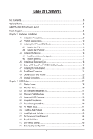
Items...6 GA-P55-UD6 Motherboard Layout 7 Block Diagram...8 Chapter 1 Hardware Installation 9 1-1 Installation Precautions 9 1-2 Product Specifications 10 1-3 Installing the CPU and CPU Cooler 13 1-3-1 Installing the CPU 13 1-3-2 Installing the CPU Cooler 15 1-4 Installing the Memory 16 - Gigabyte GA-P55-UD6 | Manual - Page 5
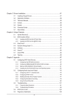
...86 Chapter 5 Appendix...87 5-1 Configuring SATA Hard Drive(s 87 5-1-1 Configuring Intel P55 SATA Controllers 87 5-1-2 Configuring JMB362/GIGABYTE SATA2 SATA Controllers 95 5-1-3 Making a SATA RAID/AHCI Driver Diskette 101 5-1-4 Installing the SATA RAID/AHCI Driver and Operating System 102 - Gigabyte GA-P55-UD6 | Manual - Page 6
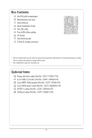
Box Contents GA-P55-UD6 motherboard Motherboard driver disk User's Manual Quick Installation Guide One IDE cable Four SATA 3Gb/s cables I/O Shield One SATA bracket 2-Way SLI bridge connector • The box contents above are for reference only and the - Gigabyte GA-P55-UD6 | Manual - Page 7
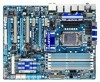
PCH_FAN RTL8111D PCIEX1_2 Intel® P55 PCIEX16_1 CODEC CD_IN SPDIF_I PCI1 PCIEX8_1 GA-P55-UD6 BATTERY TPM IC (Note 3) B_BIOS M_BIOS SPDIF_O PCI2 ACPI LED TSB43AB23 DDR3_3 DDR3_2 DDR3_1 DDR3_6 DDR3_5 DDR3_4 MD1 MD2 ATX GD1 GD2 PWR_FAN PHASE LED SYS_FAN1 JMB362 GIGABYTE SATA2 RST_SW IDE - Gigabyte GA-P55-UD6 | Manual - Page 8
x16 LGA1156 or CPU CPU CLK+/- (133 MHz) DDR3 2200/1333/1066/800 MHz Dual Channel Memory PCIe CLK (100 GIGABYTE SATA2 TSB43AB23 3 IEEE 1394a DMI Interface 1 PCI Express x4 3 PCI Express x1 2 SATA 3Gb/s or Intel® P55 x4 x1 JMB362 Switch PCIe CLK (100 MHz) PCI Express Bus Dual BIOS - Gigabyte GA-P55-UD6 | Manual - Page 9
manual and follow these procedures: • Prior to installation, do not remove or break motherboard S/N motherboard, avoid touching any metal leads or connectors. • It is best to wear an electrostatic discharge (ESD) wrist strap when handling electronic com- ponents such as a motherboard, CPU or memory - Gigabyte GA-P55-UD6 | Manual - Page 10
package (Go to GIGABYTE's website for the latest CPU support list.) L3 cache varies with CPU Chipset Intel® P55 Express Chipset Memory 6 x 1.5V DDR3 DIMM sockets supporting up to 16 GB of system memory (Note 1) Dual channel memory architecture Support for DDR3 2200/1333 - Gigabyte GA-P55-UD6 | Manual - Page 11
w iTE IT8720 chip: - 1 x floppy disk drive connector supporting up to 1 floppy disk drive Integrated in the Chipset Up to connector 1 x floppy disk drive connector 1 x IDE connector 10 x SATA 3Gb/s connectors 1 x CPU fan header 3 x system fan headers 1 x power fan header 1 x Chipset fan header 1 - Gigabyte GA-P55-UD6 | Manual - Page 12
warning CPU/System/Power fan fail warning CPU/System fan speed control (Note 5) 2 x 16 Mbit flash Use of licensed AWARD BIOS Support for DualBIOS™ PnP 1.0a, DMI 2.0, SM BIOS 2.4, ACPI 1.0b Support for @BIOS Support for Q-Flash Support for Xpress BIOS Rescue Support for Download Center Support for - Gigabyte GA-P55-UD6 | Manual - Page 13
, please do so according to your hardware specifications including the CPU, graphics card, memory, hard drive, etc. 1-3-1 Installing the CPU A. Locate the alignment keys on the motherboard CPU socket and the notches on the CPU. LGA1156 CPU Socket Alignment Key Alignment Key Pin One Corner of the - Gigabyte GA-P55-UD6 | Manual - Page 14
B. Follow the steps below to correctly install the CPU into the motherboard CPU socket. Before installing the CPU, make sure to turn off the computer and unplug the power cord from the power outlet to prevent damage to the CPU. Step 1: Gently press the CPU socket lever handle down and away from the - Gigabyte GA-P55-UD6 | Manual - Page 15
pin. Check that the Male and Female push pins are joined closely. (Refer to your CPU cooler installation manual for instructions on installing the cooler.) Step 5: After the installation, check the back of the motherboard. If the push pin is inserted as the picture above shows, the installation is - Gigabyte GA-P55-UD6 | Manual - Page 16
. If you are unable to insert the memory, switch the direction. 1-4-1 Dual Channel Memory Configuration This motherboard provides six DDR3 memory sockets and supports Dual Channel Technology. After the memory is installed, the BIOS will automatically detect the specifications and capacity of - Gigabyte GA-P55-UD6 | Manual - Page 17
to install DDR3 DIMMs on this motherboard. Notch DDR3 DIMM A DDR3 memory module has a notch, so it can only fit in one direction. Follow the steps below to correctly install your memory modules in the memory sockets. Step 1: Note the orientation of the memory module. Spread the retaining clips at - Gigabyte GA-P55-UD6 | Manual - Page 18
an expansion card: • Make sure the motherboard supports the expansion card. Carefully read the manual that came with your expansion card. • Always If necessary, go to BIOS Setup to make any required BIOS changes for your expansion card(s). 7. Install the driver provided with the expansion card - Gigabyte GA-P55-UD6 | Manual - Page 19
Configuration A. System Requirements - Windows Vista or Windows XP operating system - A CrossFireX/SLI-supported motherboard with two PCI Express x16 slots and correct driver and driver screen for enabling CrossFireX/SLI technology may differ by graphics cards. Refer to the manual that came - Gigabyte GA-P55-UD6 | Manual - Page 20
secure the SATA bracket to the chassis back panel with a screw. Step 2: Connect the SATA cable from the bracket to the SATA port on your motherboard. Step 3: Connect the power cable from the bracket to the power supply. Step 4: Plug one end of the SATA signal cable into the external SATA - Gigabyte GA-P55-UD6 | Manual - Page 21
out to an external audio system that supports digital coaxial audio. Before using this the LAN port LEDs. Connection/ Speed LED Activity LED LAN Port Connection/Speed LED: State Description from your device and then remove it from the motherboard. • When removing the cable, pull it straight - Gigabyte GA-P55-UD6 | Manual - Page 22
to per- form different functions via the audio software. Only microphones still MUST be connected to the default Mic in jack ( ). Refer to the instructions on setting up a 2/4/5.1/7.1-channel audio configuration in Chapter 5, "Configuring 2/4/5.1/7.1-Channel Audio." Hardware Installation - 22 - - Gigabyte GA-P55-UD6 | Manual - Page 23
1-9 Onboard LEDs and Buttons CPU VTT/Memory Phase Indicator LEDs This motherboard contains 4 phase indicator LEDs controlled by the system BIOS to indicate the phase status of the CPU VTT and memory. The green LEDs light up under normal working conditions; the yellow LEDs will be illuminated when an - Gigabyte GA-P55-UD6 | Manual - Page 24
Quick Buttons This motherboard has 3 quick buttons: power manually configure the BIOS settings (refer to Chapter 2, "BIOS Setup," for BIOS configurations). PHASE LED The Phase LEDs indicate the CPU loading. The higher the CPU loading, the more the number of lighted LEDs. To enable the PHASE LED - Gigabyte GA-P55-UD6 | Manual - Page 25
devices. • After installing the device and before turning on the computer, make sure the device cable has been securely attached to the connector on the motherboard. - 25 - Hardware Installation - Gigabyte GA-P55-UD6 | Manual - Page 26
supply can supply enough stable power to all the components on the motherboard. Before connecting the power connector, first make sure the power a 2x4 12V power connector is recommended by the CPU manufacturer when using an Intel Extreme Edition CPU (130W). • To meet expansion requirements, it is - Gigabyte GA-P55-UD6 | Manual - Page 27
wire is the ground wire). The motherboard supports CPU fan speed control, which requires the use of a CPU fan with fan speed control design. CPU, Chipset and system from overheating. Overheating may result in damage to the CPU/Chipset or the system may hang. • These fan headers are not configuration - Gigabyte GA-P55-UD6 | Manual - Page 28
disk drive. The types of floppy disk drives supported are: 360 KB, 720 KB, 1.2 MB, 1.44 MB, and 2.88 MB. Before connecting a floppy disk drive, be sure or slave). (For information about configuring master/slave settings for the IDE devices, read the instructions from the device manufacturers.) 39 - Gigabyte GA-P55-UD6 | Manual - Page 29
are compatible with SATA 1.5Gb/s standard. Each SATA connector supports a single SATA device. The P55 Chipset supports RAID 0, RAID 1, RAID 5 and RAID 10. Refer to Chapter 5, "Configuring SATA Hard Drive(s)," for instructions on configuring a RAID array. SATA2_5 7 7 SATA2_4 SATA2_3 SATA2_2 Pin No - Gigabyte GA-P55-UD6 | Manual - Page 30
with SATA 1.5Gb/s standard. Each SATA connector supports a single SATA device. The GIGABYTE SATA2 supports RAID 0 and RAID 1. Refer to Chapter 5, "Configuring SATA Hard Drive(s)," for instructions on configuring a RAID array. GSATA2_3 7 1 7 1 GSATA2_2 Pin No. 1 2 3 4 5 6 7 Definition GND - Gigabyte GA-P55-UD6 | Manual - Page 31
beep will be heard if no problem is detected at system startup. If a problem is detected, the BIOS may issue beeps in different patterns to indicate the problem. Refer to Chapter 5, "Troubleshooting," for information about beep codes. • HD (Hard Drive Activity LED, Blue) Connects to the hard drive - Gigabyte GA-P55-UD6 | Manual - Page 32
The front panel audio header supports Intel High Definition audio (HD) and AC'97 audio. You may connect your chassis front panel audio module to this header. Make sure the wire assignments of the module connector match the pin assignments of the motherboard header. Incorrect connection between the - Gigabyte GA-P55-UD6 | Manual - Page 33
This header supports digital S/PDIF Out and connects a S/PDIF digital audio cable (provided by expansion cards) for digital audio output from your motherboard to certain expansion digital audio cable, carefully read the manual for your expansion card. 1 Pin No. Definition 1 SPDIFO 2 GND - - Gigabyte GA-P55-UD6 | Manual - Page 34
18) F_USB1/F_USB2 (USB Headers, Blue) The headers conform to USB 2.0/1.1 specification. Each USB header can provide two USB ports via an optional USB bracket. For purchasing the optional USB bracket, please contact the local dealer. Pin No. Definition 1 Power (5V) 9 1 2 Power (5V) 10 2 3 USB - Gigabyte GA-P55-UD6 | Manual - Page 35
20) COMA (Serial Port Header, White) The COMA header can provide one serial port via an optional COM port cable. For purchasing the optional COM port cable, please contact the local dealer. 9 1 Pin No. Definition 10 2 1 NDCD- 2 NSIN 3 NSOUT 4 NDTR- 5 GND 6 NDSR- 7 NRTS- 8 NCTS- 9 NRI- - Gigabyte GA-P55-UD6 | Manual - Page 36
Hardware Installation - 36 - - Gigabyte GA-P55-UD6 | Manual - Page 37
the GIGABYTE Q-Flash or @BIOS utility. • Q-Flash allows the user to quickly and easily upgrade or back up BIOS without entering the operating system. • @BIOS is a Windows-based utility that searches and downloads the latest version of BIOS from the Internet and updates the BIOS. For instructions on - Gigabyte GA-P55-UD6 | Manual - Page 38
v6.00PG, An Energy Star Ally Copyright (C) 1984-2009, Award Software, Inc. Motherboard Model BIOS Version P55-UD6 D15 . . . . : BIOS Setup : XpressRecovery2 : Boot Menu : Qflash 07/07/2009-P55-7A89RG03C-00 Function Keys Function Keys Function Keys: : POST SCREEN Press - Gigabyte GA-P55-UD6 | Manual - Page 39
User Password Save & Exit Setup Exit Without Saving Security Chip Configuration ESC: Quit F8: Q-Flash Select Item F10: Save & Exit Setup Change CPU's Clock & Voltage F11: Save CMOS to BIOS F12: Load CMOS from BIOS BIOS Setup Program Function Keys Move the selection bar to select - Gigabyte GA-P55-UD6 | Manual - Page 40
before, without the hassles of reconfiguring the BIOS settings. First select the profile you wish to load, then press to complete. MB Intelligent Tweaker(M.I.T.) Use this menu to configure the clock, frequency and voltages of your CPU, memory, etc. Standard CMOS Features Use this menu - Gigabyte GA-P55-UD6 | Manual - Page 41
Defaults (Note 1) This item is present only if you install a CPU that supports this feature. For more information about Intel CPUs' unique features, please visit Intel's website. (Note 2) This item appears only if you install a memory module that supports this feature. - 41 - BIOS Setup - Gigabyte GA-P55-UD6 | Manual - Page 42
to decrease power consumption. Auto lets the BIOS automatically configure this setting. (Default: Auto) (Note) This item is present only if you install a CPU that supports this feature. For more information about Intel CPUs' unique features, please visit Intel's website. BIOS Setup - 42 - - Gigabyte GA-P55-UD6 | Manual - Page 43
power-saving state than C1. Auto lets the BIOS automatically configure this setting. (Default: Auto) CPU Thermal Monitor (Note) Enables or disables Intel CPU Thermal Monitor function, a CPU overheating protection function. When enabled, the CPU core frequency and voltage will be reduced when the - Gigabyte GA-P55-UD6 | Manual - Page 44
from 100 MHz to 1200 MHz. This item is configurable only if the Base Clock(BCLK) Control option is enabled. Important: It is highly recommended that the CPU frequency be set in accordance with the CPU specifications. Extreme Memory Profile (X.M.P.) (Note) Allows the BIOS to read the SPD data on XMP - Gigabyte GA-P55-UD6 | Manual - Page 45
its best performance level. DRAM Timing Selectable (SPD) Quick and Expert allows the Channel Interleaving and Rank Interleaving items to be configurable. Options are: Auto (default), Quick, Expert. (Note) This item appears only if you install a memory module that supports this feature. - 45 - BIOS - Gigabyte GA-P55-UD6 | Manual - Page 46
Extreme Memory Profile (X.M.P.) is set to Profile1 or Profile2, this item will display the value based on the SPD data on the XMP memory. Profile QPI Voltage The value displayed here is dependent on the CPU Options are: Auto (default), 1~15. tRAS Options are: Auto (default), 1~31. BIOS Setup - 46 - - Gigabyte GA-P55-UD6 | Manual - Page 47
Options are: Auto (default), 1~63. Command Rate(CMD) Options are: Auto (default), 1~3. >>>>> Channel A/B Misc Timing Control Round Trip Latency Options are: Auto (default), 1~255. - 47 - BIOS Setup - Gigabyte GA-P55-UD6 | Manual - Page 48
are: Auto (default), 1~8. Different Ranks Options are: Auto (default), 1~8. On The Same Rank Options are: Auto (default), 1~2. ESC: Exit F1: General Help F7: Optimized Defaults BIOS Setup - 48 - - Gigabyte GA-P55-UD6 | Manual - Page 49
Vdroop at different levels. Enabling Load-Line Calibration may keep the CPU voltage more constant under light and heavy CPU load. Standard Disables Load-Line Calibration and sets VDroop following Intel specifications. (De- fault) Level 1 Enables Load-Line Calibration and slightly - Gigabyte GA-P55-UD6 | Manual - Page 50
Setup Utility-Copyright (C) 1984-2009 Award Software Miscellaneous Settings Isochronous Support [Enabled] Item Help Menu Level Move Enter: Select BIOS Version BCLK CPU Frequency Memory Frequency Total Memory Size D15 133.27 MHz 3198.42 MHz 1332.80 MHz 1024 MB CPU - Gigabyte GA-P55-UD6 | Manual - Page 51
(C) 1984-2009 Award Software Standard CMOS Features Halt On Base Memory Extended Memory Total Memory [All, But Keyboard] 640K 1022M 1024M Item Help Menu on this channel. IDE Channel 0, 1 Master/Slave Configure your IDE/SATA devices by using one of the three methods below: - 51 - Gigabyte GA-P55-UD6 | Manual - Page 52
Drive Configure your IDE/SATA devices by using one of the two methods below: • Auto Lets the BIOS you wish to enter the parameters manually, refer to the information on the Memory These fields are read-only and are determined by the BIOS POST. Base Memory Also called conventional memory - Gigabyte GA-P55-UD6 | Manual - Page 53
Execute Memory Protect (Note) Delay For HDD (Secs) Full Screen LOGO Show Backup BIOS BIOS Setup. After configuring this item, set the password(s) under the CPU that supports this feature. For more information about Intel CPUs' unique features, please visit Intel's website. - 53 - BIOS - Gigabyte GA-P55-UD6 | Manual - Page 54
system such as Windows NT4.0. (Default: Disabled) No-Execute Memory Protect (Note) Enables or disables Intel Execute Disable Bit function if you install a CPU that supports this feature. For more information about Intel CPUs' unique features, please visit Intel's website. BIOS Setup - 54 - - Gigabyte GA-P55-UD6 | Manual - Page 55
Help F7: Optimized Defaults SATA RAID/AHCI Mode (Intel P55 Chipset) Enables or disables RAID for the SATA controllers integrated in the Intel P55 Chipset or configures the SATA controllers to AHCI mode. Disabled Disables RAID for the SATA controllers and configures the SATA controllers to IDE - Gigabyte GA-P55-UD6 | Manual - Page 56
SATA Port0-3 Native Mode (Intel P55 Chipset) Specifies the operating option to Disabled if you wish to install operating systems that do not support Native mode. Enabled Allows the SATA controllers to operate in Native IDE be disabled automatically. (Default: Disabled) BIOS Setup - 56 - - Gigabyte GA-P55-UD6 | Manual - Page 57
LAN Cable Is Attached... If no LAN cable is attached to the motherboard, the Status fields of all four pairs of wires will show Open 10/100/1000 Mbps in Windows mode or when the LAN Boot ROM is activated. When a Cable Problem Occurs... If a cable problem occurs on a specified pair - 57 - BIOS Setup - Gigabyte GA-P55-UD6 | Manual - Page 58
AHCI) is an interface specification that allows the storage driver to enable advanced Serial ATA features such as Native Command Queuing and hot plug. RAID Enables RAID for the SATA controller. GSATA 2_3/IDE Controller (GIGABYTE SATA2 Chip, IDE and GSATA2_2/3 Connectors) Enables or disables - Gigabyte GA-P55-UD6 | Manual - Page 59
ACPI S3 (Suspend to RAM) sleep state (default LED Control Enables or disables the onboard ACPI LEDs. Enabled allows the onboard ACPI LEDs to light up according to the system status. (Default: Enabled) Soft-Off by PWR-BTTN Configures Supported on Windows Vista operating system only. - 59 - BIOS Setup - Gigabyte GA-P55-UD6 | Manual - Page 60
system stays off upon the return of the AC power. (Default) Full-On The system is turned on upon the return of the AC power. Memory The system returns to its last known awake state upon the return of the AC power. (Note) Supported on Windows Vista operating system only. BIOS Setup - 60 - - Gigabyte GA-P55-UD6 | Manual - Page 61
CMOS Setup Utility-Copyright (C) 1984-2009 Award Software PC Health Status CPU Smart FAN Mode [Auto] Item Help Menu Level Move the detection status of the chassis intrusion detection device attached to the motherboard CI header. If the system chassis cover is removed, this BIOS Setup - Gigabyte GA-P55-UD6 | Manual - Page 62
Smart FAN Control Specifies how to control CPU fan speed. This item is configurable only if CPU Smart FAN Control is set to Enabled. Auto Lets the BIOS automatically detect the type of CPU fan installed and sets the optimal CPU fan control mode. (Default) Voltage Sets Voltage mode for a 3-pin - Gigabyte GA-P55-UD6 | Manual - Page 63
try to load Fail-Safe defaults, which are the safest and most stable BIOS settings for the motherboard. 2-10 Load Optimized Defaults CMOS Setup Utility-Copyright (C) 1984-2009 Award Software MB Intelligent Tweaker(M.I.T.) Load Optimized Defaults Standard CMOS Features Set Supervisor - Gigabyte GA-P55-UD6 | Manual - Page 64
1984-2009 Award Software MB Intelligent Tweaker(M.I.T.) Standard CMOS Features Advanced BIOS Features Integrated Peripherals Chip Configuration ESC: Quit F8: Q-Flash Select Item F10: Save & Exit Setup Change/Set/Disable Password F11: Save CMOS to BIOS F12: Load CMOS from BIOS - Gigabyte GA-P55-UD6 | Manual - Page 65
MB Intelligent Tweaker(M.I.T.) Load Optimized Defaults Standard CMOS Features Set Supervisor Password Advanced BIOS Configuration Load Fail-Safe Defaults ESC: Quit F8: Q-Flash Select Item F10: Save & Exit Setup Save Data to CMOS F11: Save CMOS to BIOS F12: Load CMOS from BIOS - Gigabyte GA-P55-UD6 | Manual - Page 66
CMOS Setup Utility-Copyright (C) 1984-2009 Award Software Security Chip Configuration Security Chip [Disabled] Item Help Menu Level Security Chip State Disabled/Deactivated Move Default) Security Chip State Displays the current settings in the security chip. BIOS Setup - 66 - - Gigabyte GA-P55-UD6 | Manual - Page 67
recommended drivers. Or click Install Single Items to manually select the drivers instructions to restart your system. You can install other applications included in the motherboard driver disk. • For USB 2.0 driver support under the Windows XP operating system, please install the Windows XP Service - Gigabyte GA-P55-UD6 | Manual - Page 68
applications that GIGABYTE develops and some free software. You can click the Install button on the right of an item to install it. 3-3 Technical Manuals This page provides GIGABYTE's application guides, content descriptions for this driver disk, and the motherboard manuals. Drivers Installation - Gigabyte GA-P55-UD6 | Manual - Page 69
3-4 Contact For the detailed contact information of the GIGABYTE Taiwan headquarter or worldwide branch offices, click the URL on this page to link to the GIGABYTE website. 3-5 System This page provides the basic system information. - 69 - Drivers Installation - Gigabyte GA-P55-UD6 | Manual - Page 70
3-6 Download Center To update the BIOS, drivers, or applications, click the Download Center button to link to the GIGABYTE website. The latest version of the BIOS, drivers, or applications will be displayed. 3-7 New Utilities This page provides a quick link to GIGABYTE's lately developed utilities - Gigabyte GA-P55-UD6 | Manual - Page 71
system and drivers are installed. MB of system memory • VESA compatible graphics card • Windows XP with SP1 or later, Windows supported. • Hard drives in RAID/AHCI mode are not supported. Installation and Configuration: Turn on your system to boot from the Windows Vista setup disk. A. Installing Windows - Gigabyte GA-P55-UD6 | Manual - Page 72
note that if there is no enough unallocated space, Xpress Recovery2 cannot save the backup file. B. Accessing Xpress Recovery2 1. Boot from the motherboard driver disk to access Xpress Recovery2 for the first time. When you see the following message: Press any key to startup Xpress Recovery2, press - Gigabyte GA-P55-UD6 | Manual - Page 73
D. Using the Restore Function in Xpress Recovery2 Select RESTORE to restore the backup to your hard drive in case the system breaks down. The RESTORE option will not be present if no backup is created before. E. Removing the Backup Step 1: If you wish to remove the backup file, select REMOVE. Step - Gigabyte GA-P55-UD6 | Manual - Page 74
system BIOS while in the Windows environment. @BIOS will download the latest BIOS file from the nearest @BIOS server 4-2-1 Updating the BIOS with the Q-Flash Utility A. Before You Begin 1. From GIGABYTE's website, download the latest compressed BIOS update file that matches your motherboard model - Gigabyte GA-P55-UD6 | Manual - Page 75
and press . • The Save Main BIOS to Drive option allows you to save the current BIOS file. • Q-Flash only supports USB flash drive or hard drives using FAT32/16/12 file system. • If the BIOS update file is saved to a hard drive in RAID/AHCI mode or a hard drive attached to an independent - Gigabyte GA-P55-UD6 | Manual - Page 76
defaults. System will re-detect all peripheral devices after a BIOS update, so we recommend that you reload BIOS defaults. CMOS Setup Utility-Copyright (C) 1984-2009 Award Software MB Intelligent Tweaker(M.I.T.) Load Optimized Defaults Standard CMOS Features Set Supervisor Password - Gigabyte GA-P55-UD6 | Manual - Page 77
. If the BIOS update file for your motherboard is not present on the @BIOS server site, please manually download the BIOS update file from GIGABYTE's website and follow the instructions in "Update the BIOS without Using the Internet Update Function" below. 2. Update the BIOS without Using the - Gigabyte GA-P55-UD6 | Manual - Page 78
in EasyTune 6 may differ by motherboard model. Grayed-out area(s) indicates that the item is not configurable or the function is not supported. Incorrectly doing overclock/overvoltage may result in damage to the hardware components such as CPU, chipset, and memory and reduce the useful life of - Gigabyte GA-P55-UD6 | Manual - Page 79
. The Dynamic Energy Saver™ 2 Interface A. Meter Mode In Meter Mode, GIGABYTE Dynamic Energy Saver™ 2 shows how much power they have saved in a set in taskbar) 14 INFO/Help 15 Motherboard Phase LED On/Off Switch (Default: On) 16 Live Utility Update (Check for the latest utility version - Gigabyte GA-P55-UD6 | Manual - Page 80
/Help 14 Motherboard Phase LED On/Off Switch (Default: On) 15 Live Utility Update (Check for CPU Enhanced Halt (C1E) and CPU EIST Function items in the BIOS Setup program are set to Enabled. (Note 2) 1: Smart FAN/CPU (default); 2: Smart FAN/CPU/VGA/HDD; 3: Smart FAN/CPU/VGA/HDD/Chipset/ Memory - Gigabyte GA-P55-UD6 | Manual - Page 81
the motherboard driver disk, go to Start>All Programs>GIGABYTE>Q-Share. exe to launch the Q-Share tool. Find the Q-Share icon to configure the the shared data folder Changes the data folder to be shared (Note) Updates Q-Share online Displays the current Q-Share version Exits Q-Share (Note) - Gigabyte GA-P55-UD6 | Manual - Page 82
4-6 Smart 6™ GIGABYTE Smart 6™ (Note 1) is designed with user-friendliness in mind, and Instructions: Select the Enable check box below the BIOS QuickBoot or OS QuickBoot item and then click Save to save the settings. SMART QuickBoost SMART QuickBoost features quick and effortless CPU overclocking - Gigabyte GA-P55-UD6 | Manual - Page 83
PATA and SATA hard drives (partitioned on NTFS file system) in Windows Vista. Instructions: In the main menu, click the Config button to open the in the main and backup BIOS simultaneously, which can prevent loss of the data in case the system/hard drive fails. Instructions: Enter the Smart 6™ - Gigabyte GA-P55-UD6 | Manual - Page 84
were moved within the hard drive or copied to an external storage device (Note 5). Instructions: Select the Enable check box at the bottom of the ON/OFF Recorder or File the User Password in the system BIOS Setup program to prevent the system time being changed by other users. Unique Features - 84 - Gigabyte GA-P55-UD6 | Manual - Page 85
from the motherboard driver disk. (Click the tab at the bottom of the left pane of the autorun screen and you'll be directed to the Install New Utilities menu. Click the Install button on the right of Smart TPM to install it.) B. Instructions for using Smart TPM: 1. After configuring the above - Gigabyte GA-P55-UD6 | Manual - Page 86
- work switch or router device supports the IEEE 802.3ad LACP standard. Please refer to your network switch or router device manual for further details. Select Realtek Ethernet Diagnostic Utility and click Install. Step 1: Insert the motherboard driver disk and select Application Software, Install - Gigabyte GA-P55-UD6 | Manual - Page 87
identical model and capacity). If you do not want to create RAID, you may prepare only one hard drive. • An empty formatted floppy disk. • Windows Vista/XP setup disk. • Motherboard driver disk. 5-1-1 Configuring Intel P55 SATA Controllers A. Installing SATA hard drive(s) in your computer Attach one - Gigabyte GA-P55-UD6 | Manual - Page 88
SATA controller mode in BIOS Setup Make sure to configure the SATA controller mode correctly in system BIOS Setup. Step 1: Turn on your computer and press to enter BIOS Setup during the POST (Power-On Self-Test). To create RAID, set SATA RAID/AHCI Mode under the Integrated Peripherals - Gigabyte GA-P55-UD6 | Manual - Page 89
C. Configuring a RAID array in RAID BIOS Enter the RAID BIOS setup utility to configure a RAID array. Skip this step and proceed with the installation of Windows operating system for a non-RAID configuration. Step 1: After the POST memory test begins and before the operating system boot begins, - Gigabyte GA-P55-UD6 | Manual - Page 90
4). RAID levels supported include RAID 0, RAID 1, Recovery, RAID 10, and RAID 5 (the selections available depend on the number of the hard drives being installed). Press to proceed. Intel(R) Matrix Storage Manager option ROM v8.9.0.1023 PCH-D wRAID5 Copyright(C) 2003-09 Intel Corporation - Gigabyte GA-P55-UD6 | Manual - Page 91
(0) Member Disk(0) [hi]-Select [ESC]-Exit Figure 7 [ENTER]-Select Menu To exit the RAID BIOS utility, press or select 5. Exit in MAIN MENU. Now, you can proceed to create the SATA RAID/AHCI driver diskette and install the SATA RAID/AHCI driver and operating system. - 91 - Appendix - Gigabyte GA-P55-UD6 | Manual - Page 92
option ROM v8.9.0.1023 PCH-D wRAID5 Copyright(C) 2003-09 Intel Corporation. All Rights Reserved. [ MAIN MENU ] 1. Create RAID Volume 2. Delete RAID Volume 5. Exit 3. Reset Disks to Non-RAID 4. Recovery Volume Options RAID Volumes : None defined. [ DISK/VOLUME INFORMATION ] Physical Disks - Gigabyte GA-P55-UD6 | Manual - Page 93
(C) 2003-09 Intel Corporation. All Rights Reserved. [ CREATE VOLUME MENU ] Name : Volume0 RAID Level : Recovery Disks : Select Disks Strip Size : N/A Capacity : 0.0 GB Sync : Continuous Create Volume [ HELP ] Select a sync option: On Request: volume is updated manually Continuous: volume - Gigabyte GA-P55-UD6 | Manual - Page 94
a RAID array, select Delete RAID Volume in MAIN MENU and press . In the DELETE VOLUME MENU section, use the up or down arrow key to select the array to be deleted and press . When prompted to confirm your selection (Figure 12), press to confirm or to abort. Intel(R) Matrix - Gigabyte GA-P55-UD6 | Manual - Page 95
Setup during the POST. In BIOS Setup, go to Integrated Peripherals. To enable RAID, see the table below for configuring different SATA controllers for RAID. Controller Connectors JMB362 eSATA ports JMB362 GSATA2_0/1 GIGABYTE GSATA2_2/3 SATA2 BIOS Settings Set eSATA Controller to Enabled - Gigabyte GA-P55-UD6 | Manual - Page 96
C. Configuring a RAID array in RAID BIOS Enter the RAID BIOS setup utility to configure a RAID array. Skip this step and proceed to the installation of Windows operating system for a non-RAID configuration. After the POST memory test begins and before the operating system boot begins, look for a - Gigabyte GA-P55-UD6 | Manual - Page 97
Array: In the main screen, press on the Create RAID Disk Drive item. Then the Create New RAID screen appears (Figure 4). Gigabyte Technology Corp. RAID Setup Utility v1.07.06 [ Create New RAID ] Name: Level: Disks: Block: Size: GRAID_ 0-Stripe Select Disk 128 KB 240 GB [ Hard Disk - Gigabyte GA-P55-UD6 | Manual - Page 98
Creation: After all of the items above are configured, the selection bar automatically jumps to the Confirm Creation item. Press . When prompted to confirm your selection (Figure 7), press to confirm or to abort. Gigabyte Technology Corp. RAID Setup Utility v1.07.06 [ Create New - Gigabyte GA-P55-UD6 | Manual - Page 99
array and press . A small window displaying the array information will appear in the center of the screen (Figure 9). Gigabyte Technology Corp. RAID Setup Utility v1.07.06 [ Main Menu ] Create RAID Disk Drive Delete RAID Disk Drive Revert HDD to Non-RAID Solve Mirror Conflict Rebuild Mirror - Gigabyte GA-P55-UD6 | Manual - Page 100
GB Normal Members(HDDx) 01 [fgTAB]-Switch Window [hi]-Select ITEM Figure 10 [ENTER]-Action [ESC]-Exit Now, you may proceed to create the SATA RAID/AHCI driver diskette and the installation of the SATA RAID/ AHCI driver and operating system. Delete the RAID Array: To delete the array, select - Gigabyte GA-P55-UD6 | Manual - Page 101
For the Intel P55, type (Figure 1): (Note) A:\>copy d:\bootdrv\imsm\32bit\*.* • For the JMB362/GIGABYTE SATA2, type (Figure 2): (Note) A:\>copy d:\bootdrv\gsata\32bit\*.* Figure 1 In Windows mode: Figure 2 Steps: 1: Use an alternative system and insert the motherboard driver disk. 2: From - Gigabyte GA-P55-UD6 | Manual - Page 102
the SATA RAID/AHCI driver and press . Then a controller menu similar to Figure 2 below will appear. Select Intel(R) ICH8R/ICH9R/ICH10R/DO/PCH SATA RAID Controller and press . Windows Setup You have chosen to configure a SCSI Adapter for use with Windows, using a device support disk - Gigabyte GA-P55-UD6 | Manual - Page 103
menu similar to Figure 3 below will appear. Select (Windows XP/2003) RAID/AHCI Driver for GIGABYTE GBB36X Controller and press . Windows Setup You have chosen to configure a SCSI Adapter for use with Windows, using a device support disk provided by an adapter manufacturer. Select the - Gigabyte GA-P55-UD6 | Manual - Page 104
one RAID array exists in your system.) For the Intel P55: Step 1: Restart your system to boot from the Windows Vista setup disk and perform standard OS installation steps. When a screen similar to that below appears, select Load Driver (Figure 4). Figure 4 Step 2: Insert the motherboard driver disk - Gigabyte GA-P55-UD6 | Manual - Page 105
Step 3: When a screen as shown in Figure 6 appears, select Intel(R) ICH8R/ICH9R/ICH10R/DO/PCH SATA RAID Controller and click Next. Figure 6 Step 4: After the driver is loaded, select the RAID/AHCI drive(s) where you want to install the operating system and then click Next to continue the OS - Gigabyte GA-P55-UD6 | Manual - Page 106
flash drive that contains the SATA RAID/ AHCI driver (Method B), then specify the location of the driver (Figure 9). Note: For users using a SATA optical drive, be sure to copy the driver files from the motherboard driver disk to a USB flash drive before installing Windows Vista (go to the BootDrv - Gigabyte GA-P55-UD6 | Manual - Page 107
Step 3: When a screen as shown in Figure 10 appears, select GIGABYTE GBB36X Controller and click Next. Figure 10 Step 4: After the driver is loaded, select the RAID/AHCI drive(s) where you want to install the operating system and then click Next to continue the OS installation (Figure 11). Figure - Gigabyte GA-P55-UD6 | Manual - Page 108
one.) For the Intel P55: Turn off your computer and replace the failed hard drive with a new one. Restart your computer. • Enabling Automatic Rebuild Step 1: When the message "Press to enter Configuration Utility" appears, press + to enter the RAID Configuration Utility. The - Gigabyte GA-P55-UD6 | Manual - Page 109
driver has been installed from the motherboard driver disk. Then launch the Intel Matrix Storage Console from All Programs in the Start menu. Step 1: On the View menu of the Intel 3: Click Next when the Rebuild RAID Volume Wizard appears. Follow the on-screen instructions to proceed. Step 4: To - Gigabyte GA-P55-UD6 | Manual - Page 110
are set to Recovery Volume in Update on Request mode, you can P55 RAID Configuration Utility. On the RECOVERY OPTIONS menu, select Enable Only Recovery Disk to show the recovery drive in the operating system. Follow the on-screen instructions to complete and exit the RAID Configuration Utility. Intel - Gigabyte GA-P55-UD6 | Manual - Page 111
SATA2: Turn off your computer and replace the failed hard drive with a new one. Use either the RAID setup utility or the GIGABYTE RAID CONFIGURER utility in the operating system to perform the rebuild. • Rebuilding with the RAID setup utility Step 1: When the message "Press to enter - Gigabyte GA-P55-UD6 | Manual - Page 112
Rebuilding in the operating system Make sure the JMB362/GIGABYTE SATA2 SATA controller driver has been installed from the motherboard driver disk. Launch the GIGABYTE RAID CONFIGURER from All Programs in the Start menu. Step 1: In the GIGABYTE RAID CONFIGURER screen, right-click on the array to be - Gigabyte GA-P55-UD6 | Manual - Page 113
5-2-1 Configuring 2/4/5.1/7.1-Channel Audio The motherboard provides six audio jacks on the back panel which support 2/4/5.1/7.1-channel time. A. Configuring Speakers (The following instructions use Windows Vista as the example operating system.) Step 1: After installing the audio driver, the HD - Gigabyte GA-P55-UD6 | Manual - Page 114
Module If your chassis provides an AC'97 front panel audio module, to activate the AC'97 functionality, click the tool icon on the Speaker Configuration tab. On the Connector Settings dialog box, select the Disable front panel jack detection check box. Click OK to complete. D. Muting the Back Panel - Gigabyte GA-P55-UD6 | Manual - Page 115
: Step 1: First, attach the connector at the end of the cable to the SPDIF_I header on your motherboard. Step 2: Secure the metal bracket to the chassis back panel with a screw. 2. Configuring S/PDIF In: On the Digital Input screen, click the Default Format tab to select the default format. Click - Gigabyte GA-P55-UD6 | Manual - Page 116
transmit audio signals to an external decoder for decoding to get the best audio quality. 1. Connecting a S/PDIF Out Cable: S/PDIF Coaxial Cable an external decoder for transmitting the S/PDIF digital audio signals. 2. Configuring S/PDIF Out: On the Digital Output screen, click the Default Format - Gigabyte GA-P55-UD6 | Manual - Page 117
the motherboard driver disk. Click the Start icon Programs, Dolby Control Center to access the utility. (The following illustration demonstrates a 7.1-speaker configuration as an example.) . Point to All 1. : Click Dolby Pro Logic IIx. The system will expand 2-channel audio for a 7.1-channel - Gigabyte GA-P55-UD6 | Manual - Page 118
the audio driver, the HD Audio Manager icon will appear in the notification area. Double-click the icon to access the HD Audio Manager. Step 2: Connect your microphone to the Mic in jack (pink) on the back panel or the Mic in jack (pink) on the front panel. Then configure the jack - Gigabyte GA-P55-UD6 | Manual - Page 119
Step 4: To raise the recording and playback volume for the microphone, click the Microphone Boost icon on the right of the Recording Volume slider and set the Microphone Boost level. Step 5: After completing the settings above, click Start, point to All Programs, point to Accessories, and then click - Gigabyte GA-P55-UD6 | Manual - Page 120
set it as the default device. Step 4: Now you can access the HD Audio Manager to configure Stereo Mix and use Sound Recorder to record the sound. 5-2-5 Using the Sound Recorder A. Recording your recording in a digital media player program that supports your audio file format. Appendix - 120 - - Gigabyte GA-P55-UD6 | Manual - Page 121
5-3 Troubleshooting 5-3-1 Frequently Asked Questions To read more FAQs for your motherboard, please go to the Support&Downloads\Motherboard\FAQ page on GIGABYTE's website. Q: In the BIOS Setup program, why are some BIOS options missing? A: Some advanced options are hidden in the BIOS Setup program - Gigabyte GA-P55-UD6 | Manual - Page 122
. Secure the CPU cooler No on the CPU. Connect the CPU cooler power cable to the motherboard. Yes The problem is verified and solved. Check if the memory is installed properly on the memory slot. No Correctly insert the memory into the memory socket. Yes The problem is verified and - Gigabyte GA-P55-UD6 | Manual - Page 123
and solved. END If the procedure above is unable to solve your problem, contact the place of purchase or local dealer for help. Or go to the Support&Downloads\Technical Service Zone page to submit your question. Our customer service staff will reply you as soon as possible. - 123 - Appendix - Gigabyte GA-P55-UD6 | Manual - Page 124
RAM - Program basic chipset registers Detect memory - Auto-detection of DRAM size, type and ECC Expand compressed BIOS code to DRAM Call chipset hook to copy BIOS back to E000 & F000 shadow RAM F000 for ESCD & DMI support Use walking 1's algorithm to CPU information including brand, SMI type and CPU - Gigabyte GA-P55-UD6 | Manual - Page 125
monitor devices Initialize INT 09 buffer 1. Program CPU internal MTRR for 0-640K memory address 2. Initialize the APIC for Pentium class CPU 3. Program early chipset according to CMOS setup Example: onboard IDE controller 4. Measure CPU speed Invoke video BIOS 1. Initialize double-byte language font - Gigabyte GA-P55-UD6 | Manual - Page 126
according to items described in Setup & Auto-configuration table 1. Assign resources to all ISA Switch back to text mode if full screen logo is supported - If errors occur, report errors & wait for keys : Build SYSID structure 1. Assign IRQs to PCI devices 2. Set up ACPI table at top of the memory 1. - Gigabyte GA-P55-UD6 | Manual - Page 127
up speed 4. Chipset final initialization 5. Power management final initialization 6. Clear screen & display summary table 7. Boot BIOS support (popup menu) Update keyboard LED & typematic rate 1. Build MP table 2. Initialize power-saving (optional) 3. Set CMOS century to 20h or 19h 4. Load CMOS time - Gigabyte GA-P55-UD6 | Manual - Page 128
GIGABYTE. Our Commitment to Preserving the Environment In addition to high-efficiency performance, all GIGABYTE motherboards local government office, your household waste disposal service or where you purchased the product for user's manual and we will be glad to help you with your effort. Appendix - Gigabyte GA-P55-UD6 | Manual - Page 129
Finally, we suggest that you practice other environmentally friendly actions by understanding and using the energy-saving features of this product (where applicable), recycling the inner and outer packaging (including shipping containers) this product was delivered in, and by disposing of or - Gigabyte GA-P55-UD6 | Manual - Page 130
Appendix - 130 - - Gigabyte GA-P55-UD6 | Manual - Page 131
- 131 - Appendix - Gigabyte GA-P55-UD6 | Manual - Page 132
Appendix - 132 - - Gigabyte GA-P55-UD6 | Manual - Page 133
- 133 - Appendix - Gigabyte GA-P55-UD6 | Manual - Page 134
Appendix - 134 - - Gigabyte GA-P55-UD6 | Manual - Page 135
231, Taiwan TEL: +886-2-8912-4000 FAX: +886-2-8912-4003 Tech. and Non-Tech. Support (Sales/Marketing) : http://ggts.gigabyte.com.tw WEB address (English): http://www.gigabyte.com.tw WEB address (Chinese): http://www.gigabyte.tw • G.B.T. INC. - U.S.A. TEL: +1-626-854-9338 FAX: +1-626-854-9339 Tech - Gigabyte GA-P55-UD6 | Manual - Page 136
.co.yu • Kazakhstan WEB address : http://www.giga-byte.kz You may go to the GIGABYTE website, select your language in the language list on the top right corner of the website. • GIGABYTE Global Service System To submit a technical or non-technical (Sales/Marketing) question, please link to: http
-
 1
1 -
 2
2 -
 3
3 -
 4
4 -
 5
5 -
 6
6 -
 7
7 -
8
-
9
-
10
-
11
-
12
-
13
-
14
-
15
-
16
-
17
-
18
-
19
-
20
-
21
-
22
-
23
-
24
-
25
-
26
-
27
-
28
-
29
-
30
-
31
-
32
-
33
-
34
-
35
-
36
-
37
-
38
-
39
-
40
-
41
-
42
-
43
-
44
-
45
-
46
-
47
-
48
-
49
-
50
-
51
-
52
-
53
-
54
-
55
-
56
-
57
-
58
-
59
-
60
-
61
-
62
-
63
-
64
-
65
-
66
-
67
-
68
-
69
-
70
-
71
-
72
-
73
-
74
-
75
-
76
-
77
-
78
-
79
-
80
-
81
-
82
-
83
-
84
-
85
-
86
-
87
-
88
-
89
-
90
-
91
-
92
-
93
-
94
-
95
-
96
-
97
-
98
-
99
-
100
-
101
-
102
-
103
-
104
-
105
-
106
-
107
-
108
-
109
-
110
-
111
-
112
-
113
-
114
-
115
-
116
-
117
-
118
-
119
-
120
-
121
-
122
-
123
-
124
-
125
-
126
-
127
-
128
-
129
-
130
-
131
-
132
-
133
-
134
-
135
-
136
 |
 |

GA-P55-UD6
LGA1156 socket motherboard for Intel
®
Core
™
i7 processor family/
Intel
®
Core
™
i5 processor family
User's Manual
Rev. 1001
12ME-P55UD6-1001R