Gigabyte GA-P55-USB3L Manual
Gigabyte GA-P55-USB3L Manual
 |
View all Gigabyte GA-P55-USB3L manuals
Add to My Manuals
Save this manual to your list of manuals |
Gigabyte GA-P55-USB3L manual content summary:
- Gigabyte GA-P55-USB3L | Manual - Page 1
GA-P55-USB3L LGA1156 socket motherboard for Intel® Core™ i7 processor family/ Intel® Core™ i5 processor family/Intel® Core™ i3 processor family User's Manual Rev. 1001 12ME-P55SB3L-1001R - Gigabyte GA-P55-USB3L | Manual - Page 2
Motherboard GA-P55-USB3L Dec. 24, 2009 Motherboard GA-P55-USB3L Dec. 24, 2009 - Gigabyte GA-P55-USB3L | Manual - Page 3
read the Quick Installation Guide included with the product. For detailed product information, carefully read the User's Manual. For instructions on how to use GIGABYTE's unique features, read or download the information on/from the Support&Downloads\Motherboard\Technology Guide page on our website - Gigabyte GA-P55-USB3L | Manual - Page 4
USB3L Motherboard Layout 7 GA-P55-USB3L Motherboard Block Diagram 8 Chapter 1 Hardware Installation 9 1-1 Installation Precautions 9 1-2 Product Specifications 10 1-3 Installing the CPU and CPU Cooler 13 1-3-1 Installing the CPU 13 1-3-2 Installing the CPU Cooler 15 1-4 Installing the Memory - Gigabyte GA-P55-USB3L | Manual - Page 5
3-1 Installing Chipset Drivers 59 3-2 Application Software 60 3-3 Technical Manuals 60 3-4 Contact...61 3-5 System...61 3-6 Download Center 62 3-7 New Utilities...62 Chapter 4 Unique Features 63 4-1 Xpress Recovery2 63 4-2 BIOS Update Utilities 66 4-2-1 Updating the BIOS with the - Gigabyte GA-P55-USB3L | Manual - Page 6
Box Contents GA-P55-USB3L motherboard Motherboard driver disk User's Manual Quick Installation Guide One IDE cable Two SATA 3Gb/s cables I/O Shield • The box contents above are for reference only and the actual items shall depend on the product package you obtain. The box contents are subject to - Gigabyte GA-P55-USB3L | Manual - Page 7
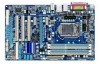
GA-P55-USB3L Motherboard Layout COAXIAL COMA LPT KB_USB ATX_12V GA-P55-USB3L PHASE LED LGA1156 PWR_FAN R_USB ATX USB30_LAN AUDIO F_AUDIO NEC D720200F1 SYS_FAN1 PCIEX1_1 (Note) CPU_FAN DDR3_2 DDR3_1 DDR3_4 DDR3_3 RTL8111D CODEC SPDIF_O CD_IN SPDIF_I PCIEX16 PCIEX1_2 PCI1 PCI2 - Gigabyte GA-P55-USB3L | Manual - Page 8
GA-P55-USB3L Motherboard Block Diagram PCIe CLK (100 MHz) 1 PCI Express x16 LGA1156 CPU CPU CLK+/- (133 MHz) DDR3 2200/1333/1066/800 MHz Dual Channel Memory x16 PCI Express Bus DMI PCI Express x1 Interface 1 PCI Express x4 (PCIEX1_2) LAN Gen 2 RJ45 RTL8111D Switch x1 x1 Gen 1 PCI - Gigabyte GA-P55-USB3L | Manual - Page 9
discharge (ESD) wrist strap when handling electronic com- ponents such as a motherboard, CPU or memory. If you do not have an ESD wrist strap, keep your hands dry installation steps or have a problem related to the use of the product, please consult a certified computer technician. - 9 - - Gigabyte GA-P55-USB3L | Manual - Page 10
1-2 Product Specifications CPU Support for an Intel® Core™ i7 series processor/Intel® Core™ i5 series processor /Intel® Core™ i3 series processor in the LGA1156 package (Go to GIGABYTE's website for the latest CPU support list.) L3 cache varies with CPU Chipset Intel® P55/H55 Express - Gigabyte GA-P55-USB3L | Manual - Page 11
via the USB brackets connected to the internal USB headers) k NEC D720200F1 chip: - Up to 2 USB 3.0 ports on the back panel Internal w 1 x 24-pin ATX main power connector Connectors (Note 7) j Only for P55 chipset. k Only for H55 chipset. - 11 - Hardware Installation - Gigabyte GA-P55-USB3L | Manual - Page 12
Use of licensed AWARD BIOS Support for DualBIOS™ PnP 1.0a, DMI 2.0, SM BIOS 2.4, ACPI 1.0b Support for @BIOS Support for Q-Flash Support for Xpress BIOS Rescue Support for Download Center Support for Xpress Install Support for Xpress Recovery2 Support for EasyTune (Note 7) Support for Dynamic Energy - Gigabyte GA-P55-USB3L | Manual - Page 13
sure that the motherboard supports the CPU. (Go to GIGABYTE's website for the latest CPU support list.) • specifications including the CPU, graphics card, memory, hard drive, etc. 1-3-1 Installing the CPU A. Locate the alignment keys on the motherboard CPU socket and the notches on the CPU. LGA1156 - Gigabyte GA-P55-USB3L | Manual - Page 14
B. Follow the steps below to correctly install the CPU into the motherboard CPU socket. Before installing the CPU, make sure to turn off the computer and unplug the power cord from the power outlet to prevent damage - Gigabyte GA-P55-USB3L | Manual - Page 15
below to correctly install the CPU cooler on the motherboard. (The following procedure uses Intel® boxed cooler as the example cooler.) Step 1: CPU cooler installation manual for instructions on installing the cooler.) Step 5: After the installation, check the back of the motherboard. If the push - Gigabyte GA-P55-USB3L | Manual - Page 16
direction. 1-4-1 Dual Channel Memory Configuration This motherboard provides four DDR3 memory sockets and supports Dual Channel Technology. After the memory is installed, the BIOS will automatically detect the specifications and capacity of the memory. Enabling Dual Channel memory mode will double - Gigabyte GA-P55-USB3L | Manual - Page 17
the power cord from the power outlet to prevent damage to the memory module. DDR3 and DDR2 DIMMs are not compatible to each other or DDR DIMMs. Be sure to install DDR3 DIMMs on this motherboard. Notch DDR3 DIMM A DDR3 memory module has a notch, so it can only fit in one direction. Follow - Gigabyte GA-P55-USB3L | Manual - Page 18
an expansion card: • Make sure the motherboard supports the expansion card. Carefully read the manual that came with your expansion card. • Always If necessary, go to BIOS Setup to make any required BIOS changes for your expansion card(s). 7. Install the driver provided with the expansion card - Gigabyte GA-P55-USB3L | Manual - Page 19
LED: State Description Blinking Data transmission or receiving is occurring Off No data transmission or receiving is occurring USB 3.0/2.0 Port The USB 3.0 port supports the USB 3.0 specification and is compatible to the USB 2.0/1.1 specification. Use this port for USB devices such as a USB - Gigabyte GA-P55-USB3L | Manual - Page 20
need connect with the port of HD Audio standard via front panel and enable the multi-channel audio feature through the audio driver. Refer to the instructions on setting up a 2/4/5.1/7.1-channel audio configuration in Chapter 5, "Configuring 2/4/5.1/7.1-Channel Audio." Hardware Installation - 20 - - Gigabyte GA-P55-USB3L | Manual - Page 21
14) SPDIF_I 15) SPDIF_O 16) F_USB1/F_USB2/(F_USB3j) 17) CLR_CMOS 18) PHASE_LED j Only for P55 chipset. Read the following guidelines before connecting external devices: • First make sure your devices are has been securely attached to the connector on the motherboard. - 21 - Hardware Installation - Gigabyte GA-P55-USB3L | Manual - Page 22
2x12 Main Power Connector) With the use of the power connector, the power supply can supply enough stable power to all the components on the motherboard. to the power connector in the correct orientation. The 12V power connector mainly supplies power to the CPU. If the 12V power connector is not - Gigabyte GA-P55-USB3L | Manual - Page 23
design. When connecting a fan cable, be sure to connect it in the correct orientation (the black connector wire is the ground wire). The motherboard supports CPU fan speed control, which requires the use of a CPU fan with fan speed control design. For optimum heat dissipation, it is recom - Gigabyte GA-P55-USB3L | Manual - Page 24
with SATA 1.5Gb/s standard. Each SATA connector supports a single SATA device. The P55 Chipset supports RAID 0, RAID 1, RAID 5, and RAID 10. Refer to Chapter 5, "Configuring SATA Hard Drive(s)," for instructions on configuring a RAID array. 7 1 SATA2_0 Pin No. Definition SATA2_1 1 GND - Gigabyte GA-P55-USB3L | Manual - Page 25
supports a single SATA device. The GIGABYTE SATA2 controller supports RAID 0, RAID 1, and JBOD. Refer to Chapter 5, "Configuring SATA Hard Drive(s)," for instructions on configuring a RAID battery provides power to keep the values (such as BIOS configurations, date, and time information) in the CMOS - Gigabyte GA-P55-USB3L | Manual - Page 26
beep will be heard if no problem is detected at system startup. If a problem is detected, the BIOS may issue beeps in different patterns to indicate the problem. Refer to Chapter 5, "Troubleshooting," for information about beep codes. • HD (Hard Drive Activity LED, Blue) Connects to the hard drive - Gigabyte GA-P55-USB3L | Manual - Page 27
The front panel audio header supports Intel High Definition audio (HD) and AC'97 audio. You may connect your chassis front panel audio module to this header. Make sure the wire assignments of the module connector match the pin assignments of the motherboard header. Incorrect connection between the - Gigabyte GA-P55-USB3L | Manual - Page 28
This header supports digital S/PDIF Out and connects a S/PDIF digital audio cable (provided by expansion cards) for digital audio output from your motherboard to certain digital audio cable, carefully read the manual for your expansion card. 1 Pin No. Definition 1 SPDIFO 2 GND Hardware - Gigabyte GA-P55-USB3L | Manual - Page 29
to do so may cause damage to the motherboard. • After system restart, go to BIOS Setup to load factory defaults (select Load Optimized Defaults) or manually configure the BIOS settings (refer to Chapter 2, "BIOS Setup," for BIOS configurations). j Only for P55 chipset. - 29 - Hardware Installation - Gigabyte GA-P55-USB3L | Manual - Page 30
18) PHASE LED The number of lighted LEDs indicates the CPU loading. The higher the CPU loading, the more the number of lighted LEDs. To enable the Phase LED display function, please first enable Dynamic Energy Saver™ 2. Refer to Chapter 4, "Dynamic Energy Saver™ 2," for more details. Hardware - Gigabyte GA-P55-USB3L | Manual - Page 31
that searches and downloads the latest version of BIOS from the Internet and updates the BIOS. For instructions on using the Q-Flash and @BIOS utilities, refer to Chapter 4, "BIOS Update Utilities." • Because BIOS flashing is potentially risky, if you do not encounter problems using the current - Gigabyte GA-P55-USB3L | Manual - Page 32
v6.00PG, An Energy Star Ally Copyright (C) 1984-2009, Award Software, Inc. Motherboard Model BIOS Version P55-USB3L E12c . . . . : BIOS Setup : XpressRecovery2 : Boot Menu : Qflash 12/04/2009-P55-7A89TG0DC-00 Function Keys Function Keys Function Keys: : POST SCREEN Press - Gigabyte GA-P55-USB3L | Manual - Page 33
Access the Q-Flash utility Display system information Save all the changes and exit the BIOS Setup program Save CMOS to BIOS Load CMOS from BIOS Main Menu Help The on-screen description of a highlighted setup option is displayed on the bottom line of the - Gigabyte GA-P55-USB3L | Manual - Page 34
Main Menu Only) F11: Save CMOS to BIOS This function allows you to save the current BIOS memory, etc. Standard CMOS Features Use this menu to configure the system time and date, hard drive types, floppy disk drive types, and the type of errors that stop the system boot, etc. Advanced BIOS - Gigabyte GA-P55-USB3L | Manual - Page 35
Enter] [Press Enter] Item Help Menu Level BIOS Version BCLK CPU Frequency Memory Frequency Total Memory Size E12c 133.27 MHz 2265.70 MHz 1332.71 Optimized Defaults (Note) This item appears only if you install a memory module that supports this feature. - 35 - BIOS Setup - Gigabyte GA-P55-USB3L | Manual - Page 36
to decrease power consumption. Auto lets the BIOS automatically configure this setting. (Default: Auto) (Note) This item is present only if you install a CPU that supports this feature. For more information about Intel CPUs' unique features, please visit Intel's website. BIOS Setup - 36 - - Gigabyte GA-P55-USB3L | Manual - Page 37
SpeedStep Technology (EIST). Depending on CPU loading, Intel EIST technology can dynamically and effectively lower the CPU voltage and core frequency to decrease average power consumption and heat production. Auto lets the BIOS automatically configure this set- ting. (Default: Auto) Bi-Directional - Gigabyte GA-P55-USB3L | Manual - Page 38
with the CPU specifications. Extreme Memory Profile (X.M.P.) (Note) Allows the BIOS to read the SPD data on XMP memory module(s) to enhance memory performance when enabled. : 0ps) (Note) This item appears only if you install a memory module that supports this feature. BIOS Setup - 38 - - Gigabyte GA-P55-USB3L | Manual - Page 39
set to Disabled, this item will display as 1.5V. When Extreme Memory Profile (X.M.P.) is set to Profile1 or Profile2, this item will display the value based on the SPD data on the XMP memory. (Note) This item appears only if you install a memory module that supports this feature. - 39 - BIOS Setup - Gigabyte GA-P55-USB3L | Manual - Page 40
Timing Control tRC Options are: Auto (default), 1~63. tRRD Options are: Auto (default), 1~7. tWTR Options are: Auto (default), 1~31. tWR Options are: Auto (default), 1~15. BIOS Setup - 40 - - Gigabyte GA-P55-USB3L | Manual - Page 41
) Options are: Auto (default), 1~3. >>>>> Channel A/B Misc Timing Control B2B CAS Delay Options are: Auto (default), 1~31. Round Trip Latency Options are: Auto (default), 1~255. - 41 - BIOS Setup - Gigabyte GA-P55-USB3L | Manual - Page 42
are: Auto (default), 1~8. Different Ranks Options are: Auto (default), 1~8. On The Same Rank Options are: Auto (default), 1~2. ESC: Exit F1: General Help F7: Optimized Defaults BIOS Setup - 42 - - Gigabyte GA-P55-USB3L | Manual - Page 43
the CPU voltage more constant under light and heavy CPU load. Disabled sets the CPU voltage following Intel specifications. (Default: Auto) Note: Enabling Load-Line Calibration may result in damage to your CPU or Voltage The default is Auto. DRAM Termination The default is Auto. - 43 - BIOS Setup - Gigabyte GA-P55-USB3L | Manual - Page 44
frequency, memory frequency, total memory size , CPU temperature, Chipset temperature, Vcore, and memory voltage. (Note) This item is present only if you install a CPU that supports this feature. For more information about Intel CPUs' unique features, please visit Intel's website. BIOS Setup - Gigabyte GA-P55-USB3L | Manual - Page 45
Optimized Defaults CMOS Setup Utility-Copyright (C) 1984-2009 Award Software Standard CMOS Features Extended Memory Total Memory 1022M 1024M Item Help Menu Level Move Enter: Select F5: Previous Values +/-/PU/ the device during the POST for faster system startup. - 45 - BIOS Setup - Gigabyte GA-P55-USB3L | Manual - Page 46
• Auto Lets the BIOS automatically detect IDE/SATA devices during the POST. (Default) • Manual Allows you to manually enter the specifications of the hard drive when the hard drive access mode is set to CHS. Access Mode Sets the hard drive access mode. Options are: Auto ( - Gigabyte GA-P55-USB3L | Manual - Page 47
and to issue warnings when a third party hardware monitor utility is installed. (Default: Disabled) (Note) This item is present only if you install a CPU that supports this feature. For more information about Intel CPUs' unique features, please visit Intel's website. - 47 - BIOS Setup - Gigabyte GA-P55-USB3L | Manual - Page 48
Windows NT4.0. (Default: Disabled) No-Execute Memory Protect (Note) Enables or disables Intel Execute Disable Bit function. This function may enhance install a CPU that supports this feature. For more information about Intel CPUs' unique features, please visit Intel's website. BIOS Setup - 48 - - Gigabyte GA-P55-USB3L | Manual - Page 49
) Disabled will turn off all of the USB functionalities below. USB Legacy Function Allows USB keyboard to be used in MS-DOS. (Default: Enabled) j Only for P55 chipset. (Note) On H55 Chipset motherboards, this item is present only when an Intel Lynnfield CPU is installed. - 49 - BIOS Setup - Gigabyte GA-P55-USB3L | Manual - Page 50
hub or a 10/100 Mbps hub, the following message will appear: Start detecting at Port..... Link Detected --> 100Mbps Cable Length= 30m (Note) On H55 Chipset motherboards, this item is present only when an Intel Lynnfield CPU is installed. BIOS Setup - 50 - - Gigabyte GA-P55-USB3L | Manual - Page 51
to AHCI mode. Advanced Host Controller Interface (AHCI) is an interface specification that allows the storage driver to enable advanced Serial ATA features such as Native Command Queuing and hot plug. RAID/IDE Enables RAID for the SATA controller; the IDE controller still operates in IDE - Gigabyte GA-P55-USB3L | Manual - Page 52
On By Mouse Power On By Keyboard x KB Power ON Password AC Back Function EuP Support [S3(STR)] [Instant-Off] [Enabled] [Enabled] [Disabled] Everyday 0 : that supports wake-up function. (Default: Enabled) (Note) Supported on Windows 7/Vista operating system only. BIOS Setup - 52 - - Gigabyte GA-P55-USB3L | Manual - Page 53
on the system at a specific time on each day or on a specific day in a month. Time configurable only if the HPET Support is set to Enabled. ( Memory The system returns to its last known awake state upon the return of the AC power. EuP Support Supported on Windows 7/Vista operating system only. - 53 - Gigabyte GA-P55-USB3L | Manual - Page 54
Displays the detection status of the chassis intrusion detection device attached to the motherboard CI header. If the system chassis cover is removed, this field for CPU temperature. When CPU temperature exceeds the threshold, BIOS will emit warning sound. Options are: Disabled (default), 60oC - Gigabyte GA-P55-USB3L | Manual - Page 55
configurable only if CPU Smart FAN Control is set to Enabled. Auto Lets the BIOS automatically detect the type of CPU fan installed and sets the optimal CPU fan fan that is not designed following Intel PWM fan specifications, selecting PWM mode may not effectively reduce the fan speed. - 55 - Gigabyte GA-P55-USB3L | Manual - Page 56
stable BIOS settings for the motherboard. BIOS F12: Load CMOS from BIOS Press on this item and then press the key to load the optimal BIOS default settings. The BIOS defaults settings help the system to operate in optimum state. Always load the Optimized defaults after updating the BIOS - Gigabyte GA-P55-USB3L | Manual - Page 57
Exit Setup Exit Without Saving ESC: Quit F8: Q-Flash Select Item F10: Save & Exit Setup Change/Set/Disable Password F11: Save CMOS to BIOS F12: Load CMOS from BIOS Press on this item and type the password with up to 8 characters and then press . You will be requested to confirm - Gigabyte GA-P55-USB3L | Manual - Page 58
on this item and press the key. This saves the changes to the CMOS and exits the BIOS Setup program. Press or to return to the BIOS Setup Main Menu. 2-13 Exit Without Saving CMOS Setup Utility-Copyright (C) 1984-2009 Award Software MB Intelligent Tweaker(M.I.T.) Load Fail - Gigabyte GA-P55-USB3L | Manual - Page 59
recommended drivers. Or click Install Single Items to manually select the drivers instructions to restart your system. You can install other applications included in the motherboard driver disk. • For USB 2.0 driver support under the Windows XP operating system, please install the Windows XP Service - Gigabyte GA-P55-USB3L | Manual - Page 60
applications that GIGABYTE develops and some free software. You can click the Install button on the right of an item to install it. 3-3 Technical Manuals This page provides GIGABYTE's application guides, content descriptions for this driver disk, and the motherboard manuals. Drivers Installation - Gigabyte GA-P55-USB3L | Manual - Page 61
3-4 Contact For the detailed contact information of the GIGABYTE Taiwan headquarter or worldwide branch offices, click the URL on this page to link to the GIGABYTE website. 3-5 System This page provides the basic system information. - 61 - Drivers Installation - Gigabyte GA-P55-USB3L | Manual - Page 62
Center To update the BIOS, drivers, or applications, click the Download Center button to link to the GIGABYTE website. The latest version of the BIOS, drivers, or applications will be displayed. 3-7 New Utilities This page provides a quick link to GIGABYTE's lately developed utilities for users - Gigabyte GA-P55-USB3L | Manual - Page 63
up your system soon after the operating system and drivers are installed. • The amount of data and hard drive System Requirements: • At least 512 MB of system memory • VESA compatible graphics card • Windows XP with SP1 USB hard drives are not supported. • Hard drives in RAID/AHCI mode are not supported - Gigabyte GA-P55-USB3L | Manual - Page 64
note that if there is no enough unallocated space, Xpress Recovery2 cannot save the backup file. B. Accessing Xpress Recovery2 1. Boot from the motherboard driver disk to access Xpress Recovery2 for the first time. When you see the following message: Press any key to startup Xpress Recovery2, press - Gigabyte GA-P55-USB3L | Manual - Page 65
D. Using the Restore Function in Xpress Recovery2 Select RESTORE to restore the backup to your hard drive in case the system breaks down. The RESTORE option will not be present if no backup is created before. E. Removing the Backup Step 1: If you wish to remove the backup file, select REMOVE. Step - Gigabyte GA-P55-USB3L | Manual - Page 66
nearest @BIOS server 4-2-1 Updating the BIOS with the Q-Flash Utility A. Before You Begin 1. From GIGABYTE's website, download the latest compressed BIOS update file that matches your motherboard model. 2. Extract the file and save the new BIOS file (e.g. p55usb3l.f1) to your floppy disk, USB flash - Gigabyte GA-P55-USB3L | Manual - Page 67
use the up or down arrow key to select Update BIOS from Drive and press . • The Save Main BIOS to Drive option allows you to save the current BIOS file. • Q-Flash only supports USB flash drive or hard drives using FAT32/16/12 file system. • If the BIOS update file is saved to a hard drive in - Gigabyte GA-P55-USB3L | Manual - Page 68
. Step 5: During the POST, press to enter BIOS Setup. Select Load Optimized Defaults and press to load BIOS defaults. System will re-detect all peripheral devices after a BIOS update, so we recommend that you reload BIOS defaults. CMOS Setup Utility-Copyright (C) 1984-2009 Award - Gigabyte GA-P55-USB3L | Manual - Page 69
. If the BIOS update file for your motherboard is not present on the @BIOS server site, please manually download the BIOS update file from GIGABYTE's website and follow the instructions in "Update the BIOS without Using the Internet Update Function" below. 2. Update the BIOS without Using the - Gigabyte GA-P55-USB3L | Manual - Page 70
and motherboard. The Memory tab provides information on the installed memory module(s). You can select memory module on a specific slot a DDR3 1066 MHz memory module(s) (or above) to enable support for Quick Boost. Available functions in EasyTune 6 may differ by motherboard model. Grayed-out - Gigabyte GA-P55-USB3L | Manual - Page 71
. The Dynamic Energy Saver™ 2 Interface A. Meter Mode In Meter Mode, GIGABYTE Dynamic Energy Saver™ 2 shows how much power they have saved in a set in taskbar) 14 INFO/Help 15 Motherboard Phase LED On/Off Switch (Default: On) 16 Live Utility Update (Check for the latest utility version - Gigabyte GA-P55-USB3L | Manual - Page 72
taskbar) 13 INFO/Help 14 Motherboard Phase LED On/Off Switch (Default: On) 15 Live Utility Update (Check for the latest utility version in the BIOS Setup program are set to Enabled. (Note 2) 1: Smart FAN/CPU (default); 2: Smart FAN/CPU/VGA/HDD; 3: Smart FAN/CPU/VGA/HDD/Chipset/ Memory. (Note - Gigabyte GA-P55-USB3L | Manual - Page 73
for using Q-Share After installing Q-Share from the motherboard driver disk, go to Start>All Programs>GIGABYTE>Q-Share. exe to launch the Q-Share tool. shared data folder Changes the data folder to be shared (Note) Updates Q-Share online Displays the current Q-Share version Exits Q-Share ( - Gigabyte GA-P55-USB3L | Manual - Page 74
4-6 Smart 6™ GIGABYTE Smart 6™ (Note 1) is designed with user-friendliness in mind, and offers a entering the operating system, delivering greater efficiency for daily use. Instructions: Select the Enable check box below the BIOS QuickBoot or OS QuickBoot item and then click Save to save - Gigabyte GA-P55-USB3L | Manual - Page 75
files from a specific backup on PATA and SATA hard drives (partitioned on NTFS file system) in Windows Vista. Instructions: In the main menu, click the data in the main and backup BIOS simultaneously, which can prevent loss of the data in case the system/hard drive fails. Instructions: Enter the - Gigabyte GA-P55-USB3L | Manual - Page 76
were moved within the hard drive or copied to an external storage device (Note 5). Instructions: Select the Enable check box at the bottom of the ON/OFF Recorder or File the User Password in the system BIOS Setup program to prevent the system time being changed by other users. Unique Features - 76 - Gigabyte GA-P55-USB3L | Manual - Page 77
to set your Bluetooth cell phone as a portable key. On the Auto Green main menu, click Configure and then click Configure BT devices. Select the Bluetooth cell .) Before creating a Bluetooth cell phone key, make sure your motherboard has a Bluetooth receiver and you have turned on the search and - Gigabyte GA-P55-USB3L | Manual - Page 78
Install All button to automatically install all motherboard drivers, including the X.H.D utility. Or you can go to the Application Software screen to individually install the X.H.D utility later. B. Using GIGABYTE eXtreme Hard Drive (X.H.D) Instructions:(Note 2) Before launching X.H.D, make sure the - Gigabyte GA-P55-USB3L | Manual - Page 79
identical model and capacity). If you do not want to create RAID, you may prepare only one hard drive. • An empty formatted floppy disk. • Windows Vista/XP setup disk. • Motherboard driver disk. 5-1-1 Configuring Intel P55 SATA Controllers A. Installing SATA hard drive(s) in your computer Attach one - Gigabyte GA-P55-USB3L | Manual - Page 80
USB 3.0 Controller Onboard SATA/IDE Device Onboard SATA/IDE Ctrl Mode Onboard Serial Port 1 Onboard Parallel Port Parallel Port Mode [Disabled] [RAID BIOS Setup. The BIOS Setup menus described in this section may differ from the exact settings for your motherboard. The actual BIOS - Gigabyte GA-P55-USB3L | Manual - Page 81
. Step 1: After the POST memory test begins and before the operating system boot begins, look for a message which says "Press to enter Configuration Utility" (Figure 2). Press + to enter the P55 RAID Configuration Utility. Intel(R) Rapid Storage Technology - option - Gigabyte GA-P55-USB3L | Manual - Page 82
Figure 4). RAID levels supported include RAID 0, RAID 1, Recovery, RAID 10, and RAID 5 (the selections available depend on the number of the hard drives being installed). Press to proceed. Intel(R) Rapid Storage Technology - option ROM - 9.5.0.1037 Copyright(C) 2003-09 Intel Corporation. All - Gigabyte GA-P55-USB3L | Manual - Page 83
(0) Member Disk(0) [hi]-Select [ESC]-Exit Figure 7 [ENTER]-Select Menu To exit the RAID BIOS utility, press or select 5. Exit in MAIN MENU. Now, you can proceed to create the SATA RAID/AHCI driver diskette and install the SATA RAID/AHCI driver and operating system. - 83 - Appendix - Gigabyte GA-P55-USB3L | Manual - Page 84
Storage Technology - option ROM - 9.5.0.1037 Copyright(C) 2003-09 Intel Corporation. All Rights Reserved. [ MAIN MENU ] 1. Create RAID Volume 2. Delete RAID Volume 5. Exit 3. Reset Disks to Non-RAID 4. Recovery Volume Options RAID Volumes : None defined. [ DISK/VOLUME INFORMATION ] Physical - Gigabyte GA-P55-USB3L | Manual - Page 85
(C) 2003-09 Intel Corporation. All Rights Reserved. [ CREATE VOLUME MENU ] Name : Volume0 RAID Level : Recovery Disks : Select Disks Strip Size : N/A Capacity : 0.0 GB Sync : Continuous Create Volume [ HELP ] Select a sync option: On Request: volume is updated manually Continuous: volume - Gigabyte GA-P55-USB3L | Manual - Page 86
RAID array, select Delete RAID Volume in MAIN MENU and press . In the DELETE VOLUME MENU section, use the up or down arrow key to select the array to be deleted and press . When prompted to confirm your selection (Figure 12), press to confirm or to abort. Intel non-RAID. - Gigabyte GA-P55-USB3L | Manual - Page 87
motherboard, the GSATA2_6 and GSATA2_7 ports are supported by the GIGABYTE SATA2 SATA controller. Then connect the power connector from your power supply to the hard drive. B. Configuring SATA controller mode in BIOS Setup Make sure to configure the SATA controller mode correctly in system BIOS - Gigabyte GA-P55-USB3L | Manual - Page 88
Menu block. Highlight the item that you wish to execute and press . Gigabyte Technology Corp. RAID Setup Utility v1.07.06 [ Main Menu ] Create RAID Disk Drive Delete RAID Disk Drive Revert HDD to Non-RAID Solve Mirror Conflict Rebuild Mirror Drive Save And Exit Setup Exit Without Saving - Gigabyte GA-P55-USB3L | Manual - Page 89
Array: In the main screen, press on the Create RAID Disk Drive item. Then the Create New RAID screen appears (Figure 4). Gigabyte Technology Corp. RAID Setup Utility v1.07.06 [ Create New RAID ] Name: Level: Disks: Block: Size: GRAID_ 0-Stripe Select Disk 128 KB 240 GB [ Hard Disk - Gigabyte GA-P55-USB3L | Manual - Page 90
Disks: After a RAID mode is selected, RAID BIOS automatically assigns the two hard drives installed as the RAID drives. 4. Set Block Size (RAID 0 only): Under to confirm or to abort. Gigabyte Technology Corp. RAID Setup Utility v1.07.06 [ Create New RAID ] Name: Level: Disks: Block: Size - Gigabyte GA-P55-USB3L | Manual - Page 91
the array information will appear in the center of the screen (Figure 9). Gigabyte Technology Corp. RAID Setup Utility v1.07.06 [ Main Menu ] Create RAID Disk Drive Delete RAID Disk Drive Revert HDD to Non-RAID Solve Mirror Conflict Rebuild Mirror Drive Save And Exit Setup Exit Without Saving - Gigabyte GA-P55-USB3L | Manual - Page 92
your settings before exiting the RAID BIOS utility, then press (Figure 10). [ Main Menu ] Create RAID Disk Drive Delete RAID Disk Drive Revert HDD to Non-RAID Solve Mirror Conflict Rebuild Mirror Drive Save And Exit Setup Exit Without Saving Gigabyte Technology Corp. RAID Setup Utility v1.07 - Gigabyte GA-P55-USB3L | Manual - Page 93
, you also can copy the SATA controller driver from the motherboard driver disk to a USB flash drive. See the instructions below about how to copy the driver in MS-DOS and Windows mode. In MS-DOS mode: Prepare a startup disk that has CD-ROM support and a blank formatted floppy disk. Steps: 1: Boot - Gigabyte GA-P55-USB3L | Manual - Page 94
5-1-4 Installing the SATA RAID/AHCI Driver and Operating System With the SATA RAID/AHCI driver diskette and correct BIOS settings, you are install a third party SCSI or RAID driver. Figure 1 Step 2: For the Intel P55: Insert the floppy disk containing the SATA RAID/AHCI driver and press . Then a - Gigabyte GA-P55-USB3L | Manual - Page 95
disk provided by an adapter manufacturer. Select the SCSI Adapter you want from the following list, or press ESC to return to the previous screen. RAID/AHCI Driver for GIGABYTE GBB36X Controller (x32) ENTER=Select F3=Exit Figure 3 Step 3: On the next screen, press to continue the - Gigabyte GA-P55-USB3L | Manual - Page 96
the Intel P55: Step 1: Restart your system to boot from the Windows Vista setup disk and perform standard OS installation steps. When a screen similar to that below appears (RAID hard drive will not be detected at this stage), select Load Driver (Figure 4). Figure 4 Step 2: Insert the motherboard - Gigabyte GA-P55-USB3L | Manual - Page 97
Step 3: When a screen as shown in Figure 6 appears, select Intel(R) ICH8R/ICH9R/ICH10R/DO/5 Series/3400 Series SATA RAID Controller and click Next. Figure 6 Step 4: After the driver is loaded, select the RAID/AHCI drive(s) where you want to install the operating system and then click Next to - Gigabyte GA-P55-USB3L | Manual - Page 98
be detected at this stage), select Load Driver (Figure 8). Figure 8 Step 2: Insert the motherboard driver disk (Method A) or the floppy disk/USB flash drive that contains the SATA RAID/ AHCI driver (Method B), then specify the location of the driver (Figure 9). Note: For users using a SATA optical - Gigabyte GA-P55-USB3L | Manual - Page 99
Step 3: When a screen as shown in Figure 10 appears, select GIGABYTE GBB36X Controller and click Next. Figure 10 Step 4: After the driver is loaded, select the RAID/AHCI drive(s) where you want to install the operating system and then click Next to continue the OS installation (Figure 11). Figure - Gigabyte GA-P55-USB3L | Manual - Page 100
you have to manually rebuild the array in the operating system (see the next page for more details). Intel(R) Rapid Storage Technology - option ROM - 9.5.0.1037 Copyright(C) 2003-09 Intel Corporation. All Rights Reserved. [ MAIN MENU ] 1. Create RAID Volume 2. Delete RAID Volume 5. Exit 3. Reset - Gigabyte GA-P55-USB3L | Manual - Page 101
has been installed from the motherboard driver disk. Then launch the Intel Rapid Stroage Technology utility from All Programs in the Start menu. Step 1: Go to the Manage menu and click Rebuild to another disk in Manage Volume. Step 2: Select a new drive to rebuild the RAID and click Rebuild. The - Gigabyte GA-P55-USB3L | Manual - Page 102
to Recovery Volume in Update on Request mode, MAIN MENU of the RAID Configuration Utility. On the RECOVERY OPTIONS menu, select Enable Only Recovery Disk to show the recovery drive in the operating system. Follow the on-screen instructions to complete and exit the RAID Configuration Utility. Intel - Gigabyte GA-P55-USB3L | Manual - Page 103
the screen. When done, the status of the array will display as Normal. Gigabyte Technology Corp. RAID Setup Utility v1.07.06 [ Main Menu ] Create RAID Disk Drive Delete RAID Disk Drive Revert HDD to Non-RAID Solve Mirror Conflict Rebuild Mirror Drive Save And Exit Setup Exit Without Saving [ Hard - Gigabyte GA-P55-USB3L | Manual - Page 104
• Rebuilding in the operating system Make sure the GIGABYTE SATA2 SATA controller driver has been installed from the motherboard driver disk. Launch the GIGABYTE RAID CONFIGURER from All Programs in the Start menu. Step 1: In the GIGABYTE RAID CONFIGURER screen, right-click on the array to be - Gigabyte GA-P55-USB3L | Manual - Page 105
jack and manually configure the jack for microphone functionality. • Audio signals will be present on both of the front and back panel audio connections simultaneously. If you want to mute the back panel audio (only supported when using an HD front panel audio module), refer to instructions on page - Gigabyte GA-P55-USB3L | Manual - Page 106
The pictures to the right show the 7.1-channel speak- 7.1-Channel Speakers: er configurations. Step 2: Connect an audio device to an audio jack. The The current connected device is dialog box appears. Select the device according to the type of device you connect. Then click OK. Front Speaker Out - Gigabyte GA-P55-USB3L | Manual - Page 107
C. Activating an AC'97 Front Panel Audio Module If your chassis provides an AC'97 front panel audio module, to activate the AC'97 functionality, click the tool icon on the Speaker Configuration tab. On the Connector Settings dialog box, select the Disable front panel jack detection check box. Click - Gigabyte GA-P55-USB3L | Manual - Page 108
S/PDIF In 1. Installing the S/PDIF In Cable: Step 1: First, attach the connector at the end of the cable to the SPDIF_I header on your motherboard. Step 2: Secure the metal bracket to the chassis back panel with a screw. 2. Configuring S/PDIF In: On the Digital Input screen, click the Default - Gigabyte GA-P55-USB3L | Manual - Page 109
B. S/PDIF Out The S/PDIF Out jacks can transmit audio signals to an external decoder for decoding to get the best audio quality. 1. Connecting a S/PDIF Out Cable: S/PDIF Coaxial Cable Connect a S/PDIF coaxial cable to an external decoder for transmitting the S/PDIF digital audio signals. 2. - Gigabyte GA-P55-USB3L | Manual - Page 110
5-2-3 Configuring Microphone Recording Step 1: After installing the audio driver, the HD Audio Manager icon will appear in the notification area. Double-click the icon to access the HD Audio Manager. Step 2: Connect your microphone - Gigabyte GA-P55-USB3L | Manual - Page 111
Step 4: To raise the recording and playback volume for the microphone, click the Microphone Boost icon on the right of the Recording Volume slider and set the Microphone Boost level. Step 5: After completing the settings above, click Start, point to All Programs, point to Accessories, and then click - Gigabyte GA-P55-USB3L | Manual - Page 112
. Be sure to save the recorded audio file upon completion. B. Playing the Recorded Sound You can play your recording in a digital media player program that supports your audio file format. Appendix - 112 - - Gigabyte GA-P55-USB3L | Manual - Page 113
5-3 Troubleshooting 5-3-1 Frequently Asked Questions To read more FAQs for your motherboard, please go to the Support&Downloads\Motherboard\FAQ page on GIGABYTE's website. Q: In the BIOS Setup program, why are some BIOS options missing? A: Some advanced options are hidden in the BIOS Setup program - Gigabyte GA-P55-USB3L | Manual - Page 114
Procedure If you encounter any troubles during system startup, follow the troubleshooting procedure below to solve the problem. START Turn off the power. Remove all peripherals, connecting cables, and power cord etc. Make sure the motherboard does not short-circuit with the chassis or - Gigabyte GA-P55-USB3L | Manual - Page 115
"Save & Exit Setup" to save changes and exit BIOS Setup. The problem is verified and solved. Turn off the computer and connect problem, contact the place of purchase or local dealer for help. Or go to the Support&Downloads\Technical Service Zone page to submit your question. Our customer service - Gigabyte GA-P55-USB3L | Manual - Page 116
GIGABYTE. Our Commitment to Preserving the Environment In addition to high-efficiency performance, all GIGABYTE motherboards life" product. Restriction of Hazardous Substances (RoHS) Directive Statement GIGABYTE products have not waste disposal service or where you purchased the product for details - Gigabyte GA-P55-USB3L | Manual - Page 117
of natural resources needed to produce electrical and electronic equipment, minimize the use of landfills for the disposal of "end of life" products, and generally improve our quality of life by ensuring that potentially hazardous substances are not released into the environment and are disposed of - Gigabyte GA-P55-USB3L | Manual - Page 118
Appendix - 118 - - Gigabyte GA-P55-USB3L | Manual - Page 119
231, Taiwan TEL: +886-2-8912-4000 FAX: +886-2-8912-4003 Tech. and Non-Tech. Support (Sales/Marketing) : http://ggts.gigabyte.com.tw WEB address (English): http://www.gigabyte.com.tw WEB address (Chinese): http://www.gigabyte.tw • G.B.T. INC. - U.S.A. TEL: +1-626-854-9338 FAX: +1-626-854-9339 Tech - Gigabyte GA-P55-USB3L | Manual - Page 120
, select your language in the language list on the top right corner of the website. • GIGABYTE Global Service System To submit a technical or non-technical (Sales/Marketing) question, please link to: http://ggts.gigabyte.com.tw Then select your language to enter the system. Appendix - 120 -
-
 1
1 -
 2
2 -
 3
3 -
 4
4 -
 5
5 -
 6
6 -
 7
7 -
8
-
9
-
10
-
11
-
12
-
13
-
14
-
15
-
16
-
17
-
18
-
19
-
20
-
21
-
22
-
23
-
24
-
25
-
26
-
27
-
28
-
29
-
30
-
31
-
32
-
33
-
34
-
35
-
36
-
37
-
38
-
39
-
40
-
41
-
42
-
43
-
44
-
45
-
46
-
47
-
48
-
49
-
50
-
51
-
52
-
53
-
54
-
55
-
56
-
57
-
58
-
59
-
60
-
61
-
62
-
63
-
64
-
65
-
66
-
67
-
68
-
69
-
70
-
71
-
72
-
73
-
74
-
75
-
76
-
77
-
78
-
79
-
80
-
81
-
82
-
83
-
84
-
85
-
86
-
87
-
88
-
89
-
90
-
91
-
92
-
93
-
94
-
95
-
96
-
97
-
98
-
99
-
100
-
101
-
102
-
103
-
104
-
105
-
106
-
107
-
108
-
109
-
110
-
111
-
112
-
113
-
114
-
115
-
116
-
117
-
118
-
119
-
120
 |
 |

GA-P55-USB3L
LGA1156 socket motherboard for Intel
®
Core
™
i7 processor family/
Intel
®
Core
™
i5 processor family/Intel
®
Core
™
i3 processor family
User's Manual
Rev. 1001
12ME-P55SB3L-1001R