Gigabyte GA-P55A-UD3 Manual
Gigabyte GA-P55A-UD3 Manual
 |
UPC - 818313009128
View all Gigabyte GA-P55A-UD3 manuals
Add to My Manuals
Save this manual to your list of manuals |
Gigabyte GA-P55A-UD3 manual content summary:
- Gigabyte GA-P55A-UD3 | Manual - Page 1
GA-P55A-UD3 LGA1156 socket motherboard for Intel® Core™ i7 processor family/ Intel® Core™ i5 processor family User's Manual Rev. 1002 12ME-P55AUD3-1002R - Gigabyte GA-P55A-UD3 | Manual - Page 2
Motherboard GA-P55A-UD3 Oct. 19, 2009 Motherboard GA-P55A-UD3 Oct. 19, 2009 - Gigabyte GA-P55A-UD3 | Manual - Page 3
the product. For detailed product information, carefully read the User's Manual. For instructions on how to use GIGABYTE's unique features, read or download the information on/from the Support&Downloads\Motherboard\Technology Guide page on our website. For product-related information, check on our - Gigabyte GA-P55A-UD3 | Manual - Page 4
Items...6 GA-P55A-UD3 Motherboard Layout 7 Block Diagram...8 Chapter 1 Hardware Installation 9 1-1 Installation Precautions 9 1-2 Product Specifications 10 1-3 Installing the CPU and CPU Cooler 13 1-3-1 Installing the CPU 13 1-3-2 Installing the CPU Cooler 15 1-4 Installing the Memory 16 - Gigabyte GA-P55A-UD3 | Manual - Page 5
61 3-1 Installing Chipset Drivers 61 3-2 Application Software 62 3-3 Technical Manuals 62 3-4 Contact...63 3-5 System...63 3-6 Download Center 64 3-7 New Utilities...64 Chapter 4 Unique Features 65 4-1 Xpress Recovery2 65 4-2 BIOS Update Utilities 68 4-2-1 Updating the BIOS with the Q-Flash - Gigabyte GA-P55A-UD3 | Manual - Page 6
Box Contents GA-P55A-UD3 motherboard Motherboard driver disk User's Manual Quick Installation Guide One IDE cable Two motherboard image is for reference only. Optional Items Floppy disk drive cable (Part No. 12CF1-1FD001-7*R) 2-port USB 2.0 bracket (Part No. 12CR1-1UB030-5*R) 2-port SATA power - Gigabyte GA-P55A-UD3 | Manual - Page 7
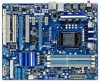
ATX_12V_2X4 LGA1156 PHASE LED ATX R_USB1 USB30_LAN NEC AUDIO F_AUDIO GA-P55A-UD3 PCIEX1_1 (Note) RTL8111D PCIEX16 PCIEX1_2 BAT CODEC PCI1 SYS_FAN1 CD_IN SPDIF_I SPDIF_O PCIEX4 DDR3_2 DDR3_1 DDR3_4 DDR3_3 PWR_FAN M_BIOS B_BIOS Marvell 9128 SYS_FAN2 GSATA3_6 GSATA3_7 Intel® P55 - Gigabyte GA-P55A-UD3 | Manual - Page 8
Memory x16 PCI Express Bus DMI Interface PCI Express x1 1 PCI Express x4 (PCIEX1_2) PCI Express x1 (PCIEX1_1) PCIe CLK (100 MHz) 2 USB 3.0/2.0 LAN RJ45 NEC RTL8111D x1 x1 PCI Express Bus x1 2 SATA 6Gb/s Marvell 9128 Intel® P55 x1 x4 Switch x1 PCI Express Bus Dual BIOS - Gigabyte GA-P55A-UD3 | Manual - Page 9
, CPU or memory. If you do not have an ESD wrist strap, keep your hands dry and first touch a metal object to eliminate static electricity. • Prior to installing the motherboard, please have it on top of an antistatic pad or within an electrostatic shielding container. • Before unplugging the power - Gigabyte GA-P55A-UD3 | Manual - Page 10
for an Intel® Core™ i7 series processor/Intel® Core™ i5 series processor in the LGA1156 package (Go to GIGABYTE's website for the latest CPU support list.) L3 cache varies with CPU Chipset Intel® P55 Express Chipset Memory Audio 4 x 1.5V DDR3 DIMM sockets supporting up to - Gigabyte GA-P55A-UD3 | Manual - Page 11
w iTE IT8720 chip Hardware Monitor w w w w w w System voltage detection CPU/System temperature detection CPU/System/Power fan speed detection CPU overheating warning CPU/System/Power fan fail warning CPU/System fan speed control (Note 5) - 11 - Hardware Installation - Gigabyte GA-P55A-UD3 | Manual - Page 12
PCIEX16 slot operates at up to x4 mode when ATI CrossFireX is enabled. (Note 5) Whether the CPU/system fan speed control function is supported will depend on the CPU/system cooler you install. (Note 6) Available functions in EasyTune may differ by motherboard model. Hardware Installation - 12 - - Gigabyte GA-P55A-UD3 | Manual - Page 13
specifications including the CPU, graphics card, memory, hard drive, etc. 1-3-1 Installing the CPU A. Locate the alignment keys on the motherboard CPU socket and the notches on the CPU. LGA1156 CPU Socket Alignment Key Alignment Key Pin One Corner of the CPU Socket LGA1156 CPU Notch Notch - Gigabyte GA-P55A-UD3 | Manual - Page 14
B. Follow the steps below to correctly install the CPU into the motherboard CPU socket. Before installing the CPU, make sure to turn off the computer and unplug the power cord from the power outlet to prevent damage to the CPU. Step 1: Gently press the CPU socket lever handle down and away from the - Gigabyte GA-P55A-UD3 | Manual - Page 15
installation manual for instructions on installing the cooler.) Step 5: After the installation, check the back of the motherboard. If the push pin is inserted as the picture above shows, the installation is complete. Step 6: Finally, attach the power connector of the CPU cooler to the CPU fan - Gigabyte GA-P55A-UD3 | Manual - Page 16
Make sure that the motherboard supports the memory. It is recommended that memory of the same capacity, brand, speed, and chips be used. (Go to GIGABYTE's website for the latest memory support list.) • Always turn off the computer and unplug the power cord from the power outlet before installing the - Gigabyte GA-P55A-UD3 | Manual - Page 17
to turn off the computer and unplug the power cord from the power outlet to prevent damage to the memory module. DDR3 and DDR2 DIMMs are not compatible to each other or DDR DIMMs. Be sure to install DDR3 DIMMs on this motherboard. Notch DDR3 DIMM A DDR3 memory module has a notch, so it can only fit - Gigabyte GA-P55A-UD3 | Manual - Page 18
motherboard supports the expansion card. Carefully read the manual that came with your expansion card. • Always turn off the computer and unplug the power cord from the power , go to BIOS Setup to make any required BIOS changes for your expansion card(s). 7. Install the driver provided with the - Gigabyte GA-P55A-UD3 | Manual - Page 19
/Speed LED: State Description Orange 1 Gbps data rate Green 100 Mbps data rate Off 10 Mbps data rate Activity LED: State Description Blinking Data transmission or receiving is occurring Off No data transmission or receiving is occurring USB 3.0/2.0 Port The USB 3.0 port supports the USB - Gigabyte GA-P55A-UD3 | Manual - Page 20
to perform different functions via the audio software. Only microphones still MUST be connected to the default Mic in jack ( ). Refer to the instructions on setting up a 2/4/5.1/7.1-channel audio configuration in Chapter 5, "Configuring 2/4/5.1/7.1-Channel Audio." Hardware Installation - 20 - - Gigabyte GA-P55A-UD3 | Manual - Page 21
COMA 19) CLR_CMOS 20) PHASE LED Read the following guidelines before power cord from the power outlet to prevent damage to the devices. • After installing the device and before turning on the computer, make sure the device cable has been securely attached to the connector on the motherboard - Gigabyte GA-P55A-UD3 | Manual - Page 22
system. • The power connectors are compatible with power supplies with 2x2 12V and 2x10 power connectors. When using a power supply providing a 2x4 12V and a 2x12 power connector, remove the protective covers from the 12V power connector and the main power connector on the motherboard. Do not insert - Gigabyte GA-P55A-UD3 | Manual - Page 23
3-pin power fan header (PWR_FAN). Most fan headers possess a foolproof insertion design. When connecting a fan cable, be sure to connect it in the correct orientation (the black connector wire is the ground wire). The motherboard supports CPU fan speed control, which requires the use of a CPU fan - Gigabyte GA-P55A-UD3 | Manual - Page 24
to SATA 3Gb/s standard and are compatible with SATA 1.5Gb/s standard. Each SATA connector supports a single SATA device. The P55 Chipset supports RAID 0, RAID 1, RAID 5, and RAID 10. Refer to Chapter 5, "Configuring SATA Hard Drive(s)," for instructions on configuring a RAID array. 7 SATA2_3 - Gigabyte GA-P55A-UD3 | Manual - Page 25
compatible with SATA 3Gb/s and SATA 1.5Gb/s standards. Each SATA connector supports a single SATA device. The Marvell 9128 supports RAID 0 and RAID 1. Refer to Chapter 5, "Configuring SATA Hard Drive(s)," for instructions battery provides power to keep the values (such as BIOS configurations, date - Gigabyte GA-P55A-UD3 | Manual - Page 26
One single short beep will be heard if no problem is detected at system startup. If a problem is detected, the BIOS may issue beeps in different patterns to indicate the problem. Refer to Chapter 5, "Troubleshooting," for information about beep codes. • HD (Hard Drive Activity LED, Blue) Connects to - Gigabyte GA-P55A-UD3 | Manual - Page 27
The front panel audio header supports Intel High Definition audio (HD) and AC'97 audio. You may connect your chassis front panel audio module to this header. Make sure the wire assignments of the module connector match the pin assignments of the motherboard header. Incorrect connection between the - Gigabyte GA-P55A-UD3 | Manual - Page 28
Power 2 SPDIFI 3 GND 1 15) SPDIF_O (S/PDIF Out Header) This header supports digital S/PDIF Out and connects a S/PDIF digital audio cable (provided by expansion cards) for digital audio output from your motherboard carefully read the manual for your expansion card. Pin No. Definition 1 SPDIFO 2 - Gigabyte GA-P55A-UD3 | Manual - Page 29
conform to USB 2.0/1.1 specification. Each USB header can provide two USB ports via an optional USB bracket. For purchasing the optional USB bracket, please contact the local dealer. Pin No. Definition 1 Power (5V) 9 1 2 Power (5V) 10 2 3 USB DX- 4 USB DY- 5 USB DX+ 6 USB DY+ 7 GND - Gigabyte GA-P55A-UD3 | Manual - Page 30
turn off your computer and unplug the power cord from the power outlet before clearing the CMOS values. • motherboard. • After system restart, go to BIOS Setup to load factory defaults (select Load Optimized Defaults) or manually configure the BIOS settings (refer to Chapter 2, "BIOS Setup," for BIOS - Gigabyte GA-P55A-UD3 | Manual - Page 31
20) PHASE LED The number of lighted LEDs indicates the CPU loading. The higher the CPU loading, the more the number of lighted LEDs. To enable the Phase LED display function, please first enable Dynamic Energy Saver™ 2. Refer to Chapter 4, "Dynamic Energy Saver™ 2," for more details. - 31 - - Gigabyte GA-P55A-UD3 | Manual - Page 32
Hardware Installation - 32 - - Gigabyte GA-P55A-UD3 | Manual - Page 33
latest version of BIOS from the Internet and updates the BIOS. For instructions on using the Q-Flash and @BIOS utilities, refer to Chapter 4, "BIOS Update Utilities." • Because BIOS flashing is potentially risky, if you do not encounter problems using the current version of BIOS, it is recommended - Gigabyte GA-P55A-UD3 | Manual - Page 34
v6.00PG, An Energy Star Ally Copyright (C) 1984-2009, Award Software, Inc. Motherboard Model BIOS Version P55A-UD3 D4c . . . . : BIOS Setup : XpressRecovery2 : Boot Menu : Qflash 10/08/2009-P55-7A89TG04C-00 Function Keys Function Keys Function Keys: : POST SCREEN Press - Gigabyte GA-P55A-UD3 | Manual - Page 35
Power Management Setup PC Health Status ESC: Quit F8: Q-Flash Load Fail-Safe Defaults Load Optimized Defaults Set Supervisor Password Set User Password Save & Exit Setup Exit Without Saving Select Item F10: Save & Exit Setup Change CPU's Clock & Voltage F11: Save CMOS to BIOS F12 - Gigabyte GA-P55A-UD3 | Manual - Page 36
the clock, frequency and voltages of your CPU, memory, etc. Standard CMOS Features Use this menu to configure the system time and date, hard drive types, floppy disk drive types, and the type of errors that stop the system boot, etc. Advanced BIOS Features Use this menu to configure the device - Gigabyte GA-P55A-UD3 | Manual - Page 37
dependent on your overall system configurations. Incorrectly doing overclock/overvoltage may result in damage to CPU, chipset, or memory and reduce the useful life of these components. (Note) This item appears only if you install a memory module that supports this feature. - 37 - BIOS Setup - Gigabyte GA-P55A-UD3 | Manual - Page 38
state to decrease power consumption. Auto lets the BIOS automatically configure this setting. (Default: Auto) (Note) This item is present only if you install a CPU that supports this feature. For more information about Intel CPUs' unique features, please visit Intel's website. BIOS Setup - 38 - Gigabyte GA-P55A-UD3 | Manual - Page 39
to boot after overclocking, please wait for 20 seconds to allow for automated system reboot, or clear the CMOS values to reset the board to default values. (Default: Disabled) (Note) This item is present only if you install a CPU that supports this feature. For more information about Intel CPUs - Gigabyte GA-P55A-UD3 | Manual - Page 40
: 700mV, 800mV (default), 900mV, 1000mV. PCI Express Clock Drive Allows you to adjust the amplitude of the PCI Express and Chipset clock. Options are: 700mV, 800mV, 900mV (default), 1000mV. (Note) This item appears only if you install a memory module that supports this feature. BIOS Setup - 40 - - Gigabyte GA-P55A-UD3 | Manual - Page 41
to set the CPU clock prior to the Chipset clock. Options are: 0ps~750ps. (Default: 0ps) Advanced Memory Settings CMOS Setup Utility-Copyright (C) 1984-2009 Award Software Advanced Memory Settings Extreme Memory Profile (X.M.P.) (Note) System Memory Multiplier (SPD) Memory Frequency (Mhz - Gigabyte GA-P55A-UD3 | Manual - Page 42
the value based on the SPD data on the XMP memory. Profile QPI Voltage The value displayed here is dependent on the CPU being used. Channel Interleaving Options are: Auto (default), Timing Control tRC Options are: Auto (default), 1~63. tRRD Options are: Auto (default), 1~7. BIOS Setup - 42 - - Gigabyte GA-P55A-UD3 | Manual - Page 43
) +0.00000V Auto QPI/Vtt Voltage 1.100V [Auto] >>> MCH/ICH PCH Core 1.050V [Auto] CPU PLL 1.800V [Auto] >>> DRAM DRAM Voltage 1.500V [Auto] DRAM Termination 0.750V [Auto] Ch -Safe Defaults ESC: Exit F1: General Help F7: Optimized Defaults - 43 - BIOS Setup - Gigabyte GA-P55A-UD3 | Manual - Page 44
keeping the CPU voltage more constant under light and heavy CPU load. Disabled sets the CPU voltage following Intel specifications. ( /Vtt Voltage The default is Auto. >>> MCH/ICH PCH Core The default is Auto. CPU PLL The default is Auto. >>> DRAM DRAM Voltage The default is Auto. DRAM Termination - Gigabyte GA-P55A-UD3 | Manual - Page 45
information on the BIOS version, CPU base clock, CPU frequency, memory frequency, total memory size , CPU temperature, Chipset temperature, Vcore, and memory voltage. (Note) This item is present only if you install a CPU that supports this feature. For more information about Intel CPUs' unique - Gigabyte GA-P55A-UD3 | Manual - Page 46
Defaults CMOS Setup Utility-Copyright (C) 1984-2009 Award Software Standard CMOS Features Base Memory Extended Memory Total Memory 640K 1022M 1024M Item Help Menu Level Move Enter: Select F5: Previous IDE/SATA devices by using one of the three methods below: BIOS Setup - 46 - - Gigabyte GA-P55A-UD3 | Manual - Page 47
you wish to enter the parameters manually, refer to the information on the boot will not stop for a keyboard or a floppy disk drive error but it will stop for all other errors. Memory These fields are read-only and are determined by the BIOS POST. Base Memory Also called conventional memory - Gigabyte GA-P55A-UD3 | Manual - Page 48
errors of the hard drive and to issue warnings when a third party hardware monitor utility is installed. (Default: Disabled) (Note) This item is present only if you install a CPU that supports this feature. For more information about Intel CPUs' unique features, please visit Intel's website. BIOS - Gigabyte GA-P55A-UD3 | Manual - Page 49
display. PEG2 Sets the PCI Express graphics card on the PCIEX4 slot as the first display. (Note) This item is present only if you install a CPU that supports this feature. For more information about Intel CPUs' unique features, please visit Intel's website. - 49 - BIOS Setup - Gigabyte GA-P55A-UD3 | Manual - Page 50
for the SATA controllers integrated in the Intel P55 Chipset. When set to Enabled, the PCH SATA Control Mode item below will be set to RAID(XHD) automatically. For details on using the GIGABYTE X.H.D utility, refer to Chaper 4, "eXtreme Hard Drive (X.H.D)." (Default: Disabled) BIOS Setup - 50 - - Gigabyte GA-P55A-UD3 | Manual - Page 51
the SATA controllers to AHCI mode. Advanced Host Controller Interface (AHCI) is an interface specification that allows the storage driver to enable advanced Serial ATA features such as Native Command Queuing and hot plug. SATA Port0-3 Native Mode (Intel P55 Chipset) Specifies the operating - Gigabyte GA-P55A-UD3 | Manual - Page 52
motherboard incorporates cable diagnostic feature designed to detect the status of the attached LAN cable. This feature will detect cabling issue speed of 10/100/1000 Mbps in Windows mode or when the LAN Boot ROM is activated. When a Cable Problem Occurs... If a cable problem BIOS Setup - 52 - - Gigabyte GA-P55A-UD3 | Manual - Page 53
boot ROM integrated with the onboard LAN chip. (Default: Disabled) Onboard USB 3.0 Controller (NEC Chip) Enables or disables the integrated USB AHCI Configures the SATA controller to AHCI mode. Advanced Host Controller Interface (AHCI) is an interface specification that allows the storage driver - Gigabyte GA-P55A-UD3 | Manual - Page 54
providing at least 1A on the +5VSB lead. (Default: Enabled) Power On by Ring Allows the system to be awakened from an ACPI sleep state by a wake-up signal from a modem that supports wake-up function. (Default: Enabled) (Note) Supported on Windows 7/Vista operating system only. BIOS Setup - 54 - - Gigabyte GA-P55A-UD3 | Manual - Page 55
On The system is turned on upon the return of the AC power. Memory The system returns to its last known awake state upon the return of the AC power. EuP Support Determines whether to let the system consume less than 1W power in S5 (shutdown) state. (Default: Disabled) Note: When this item is set - Gigabyte GA-P55A-UD3 | Manual - Page 56
. Current System/CPU Temperature Displays current system/CPU temperature. Current CPU/SYSTEM/POWER FAN Speed (RPM) Displays current CPU/system/power fan speed. CPU Warning Temperature Sets the warning threshold for CPU temperature. When CPU temperature exceeds the threshold, BIOS will emit warning - Gigabyte GA-P55A-UD3 | Manual - Page 57
3-pin CPU fan. PWM Sets PWM mode for a 4-pin CPU fan. Note: The Voltage mode can be set for a 3-pin CPU fan or a 4-pin CPU fan. However, for a 4-pin CPU fan that is not designed following Intel PWM fan specifications, selecting PWM mode may not effectively reduce the fan speed. - 57 - BIOS Setup - Gigabyte GA-P55A-UD3 | Manual - Page 58
for the motherboard. 2-10 Load Optimized Defaults CMOS Setup Utility-Copyright (C) 1984-2009 Award Software MB Intelligent Tweaker(M.I.T.) Standard CMOS Features Advanced BIOS Features Integrated Peripherals Power Management Setup PC Health Status ESC: Quit F8: Q-Flash Load - Gigabyte GA-P55A-UD3 | Manual - Page 59
Standard CMOS Features Advanced BIOS Features Integrated Peripherals Power Management SetupEnter Password: PC boot. In BIOS Setup, you must enter the supervisor password if you wish to make changes to BIOS settings. The user password only allows you to view the BIOS - Gigabyte GA-P55A-UD3 | Manual - Page 60
Setup CMOS Setup Utility-Copyright (C) 1984-2009 Award Software MB Intelligent Tweaker(M.I.T.) Standard CMOS Features Advanced BIOS Features Integrated Peripherals Power Management Setup PC Health Status ESC: Quit F8: Q-Flash Load Fail-Safe Defaults Load Optimized Defaults - Gigabyte GA-P55A-UD3 | Manual - Page 61
are installed, follow the on-screen instructions to restart your system. You can install other applications included in the motherboard driver disk. • For USB 2.0 driver support under the Windows XP operating system, please install the Windows XP Service Pack 1 or later. After installing the SP1 - Gigabyte GA-P55A-UD3 | Manual - Page 62
that GIGABYTE develops and some free software. You can click the Install button on the right of an item to install it. 3-3 Technical Manuals This page provides GIGABYTE's application guides, content descriptions for this driver disk, and the motherboard manuals. Drivers Installation - 62 - - Gigabyte GA-P55A-UD3 | Manual - Page 63
3-4 Contact For the detailed contact information of the GIGABYTE Taiwan headquarter or worldwide branch offices, click the URL on this page to link to the GIGABYTE website. 3-5 System This page provides the basic system information. - 63 - Drivers Installation - Gigabyte GA-P55A-UD3 | Manual - Page 64
3-6 Download Center To update the BIOS, drivers, or applications, click the Download Center button to link to the GIGABYTE website. The latest version of the BIOS, drivers, or applications will be displayed. 3-7 New Utilities This page provides a quick link to GIGABYTE's lately developed utilities - Gigabyte GA-P55A-UD3 | Manual - Page 65
created with Xpress Recovery cannot be restored using Xpress Recovery2. • USB hard drives are not supported. • Hard drives in RAID/AHCI mode are not supported. Installation and Configuration: Turn on your system to boot from the Windows Vista setup disk. A. Installing Windows Vista and Partitioning - Gigabyte GA-P55A-UD3 | Manual - Page 66
the operating system is installed, right-click the Computer icon on your desktop and select Manage. Go to Disk Management to check disk allocation. cannot save the backup file. B. Accessing Xpress Recovery2 1. Boot from the motherboard driver disk to access Xpress Recovery2 for the first time. When - Gigabyte GA-P55A-UD3 | Manual - Page 67
D. Using the Restore Function in Xpress Recovery2 Select RESTORE to restore the backup to your hard drive in case the system breaks down. The RESTORE option will not be present if no backup is created before. E. Removing the Backup Step 1: If you wish to remove the backup file, select REMOVE. Step - Gigabyte GA-P55A-UD3 | Manual - Page 68
However, if the BIOS update file is saved to a hard drive in RAID/AHCI mode or a hard drive attached to an independent IDE/SATA controller, use the key during the POST to access Q-Flash. Award Modular BIOS v6.00PG, An Energy Star Ally Copyright (C) 1984-2009, Award Software, Inc. P55A-UD3 D4c - Gigabyte GA-P55A-UD3 | Manual - Page 69
key to select Update BIOS from Drive and press . • The Save Main BIOS to Drive option allows you to save the current BIOS file. • Q-Flash only supports USB flash drive or hard drives using FAT32/16/12 file system. • If the BIOS update file is saved to a hard drive in RAID/AHCI mode or a hard - Gigabyte GA-P55A-UD3 | Manual - Page 70
. As the system boots, you should see the new BIOS version is present on the POST screen. Step 5: During the POST, press to enter BIOS Setup. Select Load Optimized Defaults and press to load BIOS defaults. System will re-detect all peripheral devices after a BIOS update, so we - Gigabyte GA-P55A-UD3 | Manual - Page 71
. If the BIOS update file for your motherboard is not present on the @BIOS server site, please manually download the BIOS update file from GIGABYTE's website and follow the instructions in "Update the BIOS without Using the Internet Update Function" below. 2. Update the BIOS without Using the - Gigabyte GA-P55A-UD3 | Manual - Page 72
in EasyTune 6 may differ by motherboard model. Grayed-out area(s) indicates that the item is not configurable or the function is not supported. Incorrectly doing overclock/overvoltage may result in damage to the hardware components such as CPU, chipset, and memory and reduce the useful life of - Gigabyte GA-P55A-UD3 | Manual - Page 73
in taskbar) 14 INFO/Help 15 Motherboard Phase LED On/Off Switch (Default: On) 16 Live Utility Update (Check for the latest utility version) • The above data is for reference only. Actual performance may vary depending on motherboard model. • CPU Power and Power Scores are for reference only - Gigabyte GA-P55A-UD3 | Manual - Page 74
to run in taskbar) 13 INFO/Help 14 Motherboard Phase LED On/Off Switch (Default: On) 15 Live Utility Update (Check for the latest utility version) C. Stealth Mode In Stealth Mode, the system continues to work with the user-defined power saving settings, even after the system is restarted - Gigabyte GA-P55A-UD3 | Manual - Page 75
resources. Directions for using Q-Share After installing Q-Share from the motherboard driver disk, go to Start>All Programs>GIGABYTE>Q-Share. exe to launch data folder Changes the data folder to be shared (Note) Updates Q-Share online Displays the current Q-Share version Exits Q-Share ( - Gigabyte GA-P55A-UD3 | Manual - Page 76
the mouse button. SMART QuickBoot SMART QuickBoot speeds up the system boot-up process and shortens the waiting time for entering the operating system, delivering greater efficiency for daily use. Instructions: Select the Enable check box below the BIOS QuickBoot or OS QuickBoot item and then click - Gigabyte GA-P55A-UD3 | Manual - Page 77
, and remind users of the dates. It also stores the recorded data in the main and backup BIOS simultaneously, which can prevent loss of the data in case the system/hard drive fails. Instructions: Enter the Smart 6™ password to launch the SMART DualBIOS utility. You can record personal passwords and - Gigabyte GA-P55A-UD3 | Manual - Page 78
drive or copied to an external storage device (Note 5). Instructions: Select the Enable check box at the bottom of the backup time, the backup will be performed on the next boot. We recommend that you preserve at least 25 percent of BIOS Setup program to prevent the system time being changed by other - Gigabyte GA-P55A-UD3 | Manual - Page 79
Green main menu and click Save to save the settings. Button Standby Suspend Disable Description Enters Power on Suspend mode Enters Suspend to RAM mode Disables this function The Bluetooth dongle included in the motherboard package(Note 2) allows you to wake up the system from Suspend to - Gigabyte GA-P55A-UD3 | Manual - Page 80
1: Configure the system BIOS Enter the system BIOS Setup program, set eXtreme Hard Disk (X.H.D) under the Integrated Peripherals menu to Enabled to enable RAID for the Intel SATA controllers. Step 2: Install the RAID driver and operating system The X.H.D utility supports Windows 7/Vista/XP. Before - Gigabyte GA-P55A-UD3 | Manual - Page 81
," to identify the SATA controller for the SATA port. (For example, on this motherboard, the SATA2_0, SATA2_1, SATA2_2, SATA2_3, SATA2_4 and SATA2_5 ports are supported by P55 Chipset.) Then connect the power connector from your power supply to the hard drive. (Note 1) Skip this step if you do not - Gigabyte GA-P55A-UD3 | Manual - Page 82
press to enter BIOS Setup during the POST (Power-On Self-Test). To create RAID, set PCH SATA Control Mode under the Integrated Peripherals menu to RAID(XHD) (Figure 1) (Disabled by default). If you do not want to create RAID, set this item to Disabled or AHCI. CMOS Setup Utility-Copyright - Gigabyte GA-P55A-UD3 | Manual - Page 83
. Step 1: After the POST memory test begins and before the operating system boot begins, look for a message which says "Press to enter Configuration Utility" (Figure 2). Press + to enter the P55 RAID Configuration Utility. Intel(R) Matrix Storage Manager option ROM - Gigabyte GA-P55A-UD3 | Manual - Page 84
press . Then, select a RAID level (Figure 4). RAID levels supported include RAID 0, RAID 1, Recovery, RAID 10, and RAID 5 (the stripe block size, press . Intel(R) Matrix Storage Manager option ROM v8.9.0.1023 PCH-D wRAID5 Copyright(C) 2003-09 Intel Corporation. All Rights Reserved. [ - Gigabyte GA-P55A-UD3 | Manual - Page 85
cancel (Figure 6). Intel(R) Matrix Storage Manager option ROM v8.9.0.1023 PCH-D wRAID5 Copyright(C) 2003-09 Intel Corporation. All Rights BIOS utility, press or select 5. Exit in MAIN MENU. Now, you can proceed to create the SATA RAID/AHCI driver diskette and install the SATA RAID/AHCI driver - Gigabyte GA-P55A-UD3 | Manual - Page 86
is hidden. Step 1: select Create RAID Volume in MAIN MENU and press (Figure 8). Intel(R) Matrix Storage Manager option ROM v8.9.0.1023 PCH-D wRAID5 Copyright(C) 2003-09 Intel Corporation. All Rights Reserved. [ MAIN MENU ] 1. Create RAID Volume 2. Delete RAID Volume 5. Exit 3. Reset - Gigabyte GA-P55A-UD3 | Manual - Page 87
Intel(R) Matrix Storage Manager option ROM v8.9.0.1023 PCH-D wRAID5 Copyright(C) 2003-09 Intel update data from the master drive to the recovery drive manually using the Update Volume function of the Intel Request: volume is updated manually Continuous: volume is updated automatically [hi]-Change - Gigabyte GA-P55A-UD3 | Manual - Page 88
When prompted to confirm your selection (Figure 12), press to confirm or to abort. Intel(R) Matrix Storage Manager option ROM v8.9.0.1023 PCH-D wRAID5 Copyright(C) 2003-09 Intel Corporation. All Rights Reserved. Name Volume0 Level RAID0(Stripe) [ DELETE VOLUME MENU ] Drives 2 Capacity - Gigabyte GA-P55A-UD3 | Manual - Page 89
to enter BIOS Setup during the POST (Power-On Self-Test). Make sure GSATA Controller under the Integrated Peripherals menu is enabled. Then set GSATA Ctrl Mode to IDE or AHCI, depending on your requirements (Figure 1). (In AHCI mode, installation of the SATA AHCI driver is required during - Gigabyte GA-P55A-UD3 | Manual - Page 90
Disks Free Physical Disks PD 0: WDC WD800JD-22L PD 8: WDC WD800JD-22L Information Vendor ID : Device ID : Revision ID : BIOS Version : Firmware Version : PCIe Speed rate : Configure SATA as : 1B4B 91A3 B1 1.0.0.1006 2.1.0.1314 2.56Gbps IDE Mode Help Marvell RAID on chip controller. ENTER - Gigabyte GA-P55A-UD3 | Manual - Page 91
hard drives when creating the array. 5. VD Name: Enter an array name with 1~10 letters (letters cannot be special characters). Marvell BIOS Setup (c) 2009 Marvell Technology Group Ltd. Configure -> Select free disksCreate Virtual Disk HBA 0 : Marvell 0 Virtual Disks Free Physical Disks * PD - Gigabyte GA-P55A-UD3 | Manual - Page 92
New_VD PD 0: WDC WD800JD-22L PD 8: WDC WD800JD-22L Free Physical Disks Information Vendor ID : Device ID : Revision ID : BIOS Version : Firmware Version : PCIe Speed rate : Configure SATA as : 1B4B 91A3 B1 1.0.0.1006 2.1.0.1314 2.56Gbps IDE Mode Help Marvell RAID on chip controller. ENTER - Gigabyte GA-P55A-UD3 | Manual - Page 93
the SATA driver diskette (for AHCI mode) and the installation of the SATA driver and operating Device ID : Revision ID : BIOS Version : Firmware Version : PCIe Speed rate : Configure SATA as : . To install the utility, insert the motherboard driver disk, then go to Application Software\Install - Gigabyte GA-P55A-UD3 | Manual - Page 94
copy the SATA controller driver from the motherboard driver disk to a USB flash drive. See the instructions below about how to copy the driver in MS-DOS and Windows mode. In MS-DOS mode: Prepare a startup disk that has CD-ROM support and a blank formatted floppy disk. Steps: 1: Boot from the startup - Gigabyte GA-P55A-UD3 | Manual - Page 95
you to specify additional device. Windows Setup Press F6 if you need to install a third party SCSI or RAID driver. Figure 1 Step 2: For the Intel P55: Insert the floppy disk containing the SATA RAID/AHCI driver and press . Then a controller menu similar to Figure 2 below will appear. Select - Gigabyte GA-P55A-UD3 | Manual - Page 96
SATA AHCI driver and press . The screen will display two drivers, driver installation. Windows Setup You have chosen to configure a SCSI Adapter for use with Windows, using a device support disk provided by an adapter manufacturer. Select the SCSI Adapter you want from the following list - Gigabyte GA-P55A-UD3 | Manual - Page 97
the Intel P55: Step 1: Restart your system to boot from the Windows Vista setup disk and perform standard OS installation steps. When a screen similar to that below appears, select Load Driver (Figure 4). Step 2: Figure 4 Insert the motherboard driver disk (Method A) or the floppy disk/USB flash - Gigabyte GA-P55A-UD3 | Manual - Page 98
Step 3: When a screen as shown in Figure 6 appears, select Intel(R) ICH8R/ICH9R/ICH10R/DO/PCH SATA RAID Controller and click Next. Figure 6 Step 4: After the driver is loaded, select the RAID/AHCI drive(s) where you want to install the operating system and then click Next to continue the OS - Gigabyte GA-P55A-UD3 | Manual - Page 99
drive must have equal or greater capacity than the old one.) For the Intel P55: Turn off your computer and replace the failed hard drive with a new one stage, you have to manually rebuild the array in the operating system (see the next page for more details). Intel(R) Matrix Storage Manager option - Gigabyte GA-P55A-UD3 | Manual - Page 100
chipset driver has been installed from the motherboard driver disk. Then launch the Intel Matrix Storage Console from All Programs in the Start menu. Step 1: On the View menu of the Intel RAID Volume Wizard appears. Follow the on-screen instructions to proceed. Step 4: To check the rebuild status - Gigabyte GA-P55A-UD3 | Manual - Page 101
are set to Recovery Volume in Update on Request mode, you can P55 RAID Configuration Utility. On the RECOVERY OPTIONS menu, select Enable Only Recovery Disk to show the recovery drive in the operating system. Follow the on-screen instructions to complete and exit the RAID Configuration Utility. Intel - Gigabyte GA-P55A-UD3 | Manual - Page 102
the selection bar to the array to be rebuilt (for example, VD 0: New_VD) and press and then select Rebuild. Press again. Marvell BIOS Setup (c) 2009 Marvell Technology Group Ltd. Topology HBA 0 : Marvell 0 Virtual Disks VD 0: New_VD PD 8: WDC WD8[0D0JeDle-t2e]2L Free Physical Disks - Gigabyte GA-P55A-UD3 | Manual - Page 103
: Operation F10: Exit/Save ESC: Return Resume the Stopped Rebuild Process To resume the stopped rebuild process, enter the GSATA RAID Configuration menu in BIOS Setup again. Move the selection bar to the array to be rebuilt (for example, VD 0: New_VD). Press on this array and select Resume - Gigabyte GA-P55A-UD3 | Manual - Page 104
audio driver. For manually configure the jack for microphone functionality. • Audio signals will be present on both of the front and back panel audio connections simultaneously. If you want to mute the back panel audio (only supported when using an HD front panel audio module), refer to instructions - Gigabyte GA-P55A-UD3 | Manual - Page 105
the type of device you connect. Then click OK. Step 3: On the Speakers screen, click the Speaker Configuration tab. In the Speaker Configuration list, select Stereo, Quadraphonic, 5.1 Speaker, or 7.1 Speaker according to the type of speaker configuration you wish to set up. Then the speaker setup is - Gigabyte GA-P55A-UD3 | Manual - Page 106
S/PDIF In 1. Installing the S/PDIF In Cable: Step 1: First, attach the connector at the end of the cable to the SPDIF_I header on your motherboard. Step 2: Secure the metal bracket to the chassis back panel with a screw. 2. Configuring S/PDIF In: On the Digital Input screen, click the Default - Gigabyte GA-P55A-UD3 | Manual - Page 107
B. S/PDIF Out The S/PDIF Out jacks can transmit audio signals to an external decoder for decoding to get the best audio quality. 1. Connecting a S/PDIF Out Cable: S/PDIF Coaxial Cable S/PDIF Optical Cable Connect a S/PDIF coaxial cable or a S/PDIF optical cable (either one) to an external decoder - Gigabyte GA-P55A-UD3 | Manual - Page 108
5-2-3 Configuring Microphone Recording Step 1: After installing the audio driver, the HD Audio Manager icon will appear in the notification area. Double-click the icon to access the HD Audio Manager. Step 2: Connect your microphone - Gigabyte GA-P55A-UD3 | Manual - Page 109
Step 4: To raise the recording and playback volume for the microphone, click the Microphone Boost icon on the right of the Recording Volume slider and set the Microphone Boost level. Step 5: After completing the settings above, click Start, point to All Programs, point to Accessories, and then click - Gigabyte GA-P55A-UD3 | Manual - Page 110
. Be sure to save the recorded audio file upon completion. B. Playing the Recorded Sound You can play your recording in a digital media player program that supports your audio file format. Appendix - 110 - - Gigabyte GA-P55A-UD3 | Manual - Page 111
boots successfully 1 long, 3 short: Keyboard error 2 short: CMOS setting error 1 long, 9 short: BIOS ROM error 1 long, 1 short: Memory or motherboard error Continuous long beeps: Graphics card not inserted properly 1 long, 2 short: Monitor or graphics card error Continuous short beeps: Power - Gigabyte GA-P55A-UD3 | Manual - Page 112
Procedure If you encounter any troubles during system startup, follow the troubleshooting procedure below to solve the problem. START Turn off the power. Remove all peripherals, connecting cables, and power cord etc. Make sure the motherboard does not short-circuit with the chassis or - Gigabyte GA-P55A-UD3 | Manual - Page 113
When the computer is turned on, is the CPU cooler running? No The power supply, CPU or CPU socket might fail. Yes Check if there is display on your monitor. Yes Turn off the computer. Plug in the keyboard and mouse and restart the computer. The problem is verified and solved. No The graphics - Gigabyte GA-P55A-UD3 | Manual - Page 114
cannot, however, assume any responsibility for errors or omissions in this text. Also note performance, all GIGABYTE motherboards fulfill European Union your household waste disposal service or where you purchased the Care number listed in your product's user's manual and we will be glad to help - Gigabyte GA-P55A-UD3 | Manual - Page 115
Finally, we suggest that you practice other environmentally friendly actions by understanding and using the energy-saving features of this product (where applicable), recycling the inner and outer packaging (including shipping containers) this product was delivered in, and by disposing of or - Gigabyte GA-P55A-UD3 | Manual - Page 116
Appendix - 116 - - Gigabyte GA-P55A-UD3 | Manual - Page 117
- 117 - Appendix - Gigabyte GA-P55A-UD3 | Manual - Page 118
Appendix - 118 - - Gigabyte GA-P55A-UD3 | Manual - Page 119
CO., LTD. Address: No.6, Bau Chiang Road, Hsin-Tien, Taipei 231, Taiwan TEL: +886-2-8912-4000 FAX: +886-2-8912-4003 Tech. and Non-Tech. Support (Sales/Marketing) : http://ggts.gigabyte.com.tw WEB address (English): http://www.gigabyte.com.tw WEB address (Chinese): http://www.gigabyte.tw • G.B.T. INC - Gigabyte GA-P55A-UD3 | Manual - Page 120
WEB address : http://www.gigabyte.kz You may go to the GIGABYTE website, select your language in the language list on the top right corner of the website. • GIGABYTE Global Service System To submit a technical or non-technical (Sales/Marketing) question, please link to: http://ggts.gigabyte.com.tw
-
 1
1 -
 2
2 -
 3
3 -
 4
4 -
 5
5 -
 6
6 -
 7
7 -
8
-
9
-
10
-
11
-
12
-
13
-
14
-
15
-
16
-
17
-
18
-
19
-
20
-
21
-
22
-
23
-
24
-
25
-
26
-
27
-
28
-
29
-
30
-
31
-
32
-
33
-
34
-
35
-
36
-
37
-
38
-
39
-
40
-
41
-
42
-
43
-
44
-
45
-
46
-
47
-
48
-
49
-
50
-
51
-
52
-
53
-
54
-
55
-
56
-
57
-
58
-
59
-
60
-
61
-
62
-
63
-
64
-
65
-
66
-
67
-
68
-
69
-
70
-
71
-
72
-
73
-
74
-
75
-
76
-
77
-
78
-
79
-
80
-
81
-
82
-
83
-
84
-
85
-
86
-
87
-
88
-
89
-
90
-
91
-
92
-
93
-
94
-
95
-
96
-
97
-
98
-
99
-
100
-
101
-
102
-
103
-
104
-
105
-
106
-
107
-
108
-
109
-
110
-
111
-
112
-
113
-
114
-
115
-
116
-
117
-
118
-
119
-
120
 |
 |

GA-P55A-UD3
LGA1156 socket motherboard for Intel
®
Core
™
i7 processor family/
Intel
®
Core
™
i5 processor family
User's Manual
Rev. 1002
12ME-P55AUD3-1002R