Gigabyte GA-P55M-UD2 Manual
Gigabyte GA-P55M-UD2 Manual
 |
UPC - 818313008589
View all Gigabyte GA-P55M-UD2 manuals
Add to My Manuals
Save this manual to your list of manuals |
Gigabyte GA-P55M-UD2 manual content summary:
- Gigabyte GA-P55M-UD2 | Manual - Page 1
GA-P55M-UD2 LGA1156 socket motherboard for Intel® Core™ i7 processor family/ Intel® Core™ i5 processor family User's Manual Rev. 1001 12ME-P55MUD2-1001R - Gigabyte GA-P55M-UD2 | Manual - Page 2
Motherboard GA-P55M-UD2 Jul. 24, 2009 Motherboard GA-P55M-UD2 Jul. 24, 2009 - Gigabyte GA-P55M-UD2 | Manual - Page 3
set-up of the product, read the Quick Installation Guide included with the product. For detailed product information, carefully read the User's Manual. For instructions on how to use GIGABYTE's unique features, read or download the information on/from the Support&Downloads\Motherboard\Technology - Gigabyte GA-P55M-UD2 | Manual - Page 4
Items...6 GA-P55M-UD2 Motherboard Layout 7 Block Diagram...8 Chapter 1 Hardware Installation 9 1-1 Installation Precautions 9 1-2 Product Specifications 10 1-3 Installing the CPU and CPU Cooler 13 1-3-1 Installing the CPU 13 1-3-2 Installing the CPU Cooler 15 1-4 Installing the Memory 16 - Gigabyte GA-P55M-UD2 | Manual - Page 5
Hard Drive(s 79 5-1-1 Configuring Intel P55 SATA Controllers 79 5-1-2 Configuring GIGABYTE SATA2 SATA Controller 87 5-1-3 Making a SATA RAID/AHCI Driver Diskette 93 5-1-4 Installing the SATA RAID/AHCI Driver and Operating System 94 5-2 Configuring Audio Input and Output 105 5-2-1 Configuring - Gigabyte GA-P55M-UD2 | Manual - Page 6
Box Contents GA-P55M-UD2 motherboard Motherboard driver disk User's Manual Quick Installation Guide One IDE cable Two SATA 3Gb/s cables I/O Shield • The box contents above are for reference only and the actual items shall depend on the product - Gigabyte GA-P55M-UD2 | Manual - Page 7
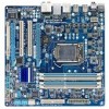
LGA1156 PHASE LED ATX IT8720 GA-P55M-UD2 DDR3_2 DDR3_1 DDR3_4 DDR3_3 R_USB_1 USB_1394_ESATA USB_LAN RTL8111D AUDIO BAT F_AUDIO PCIEX16 PCI1 CODEC PCI2 CD_IN PCIEX4 SPDIF_O SPDIF_I FDD B_BIOS M_BIOS IDE GIGABYTE SATA2 TSB43AB23 Intel® P55 SATA2_4 CLR_CMOS SYS_FAN GSATA2_1 GSATA2_0 - Gigabyte GA-P55M-UD2 | Manual - Page 8
LGA1156 CPU CPU CLK+/- (133 MHz) DDR3 2200/1333/1066/800 MHz Dual Channel Memory x16 PCI Express Bus DMI Interface PCI Express Bus x4 x1 x1 RTL8111D RJ45 GIGABYTE SATA2 1 PCI Express x4 LAN 2 SATA 3Gb/s ATA-133/100/66/33 IDE Channel PCI Bus TSB43AB23 Intel® P55 CODEC Dual BIOS 6 SATA - Gigabyte GA-P55M-UD2 | Manual - Page 9
, CPU or memory. If you do not have an ESD wrist strap, keep your hands dry and first touch a metal object to eliminate static electricity. • Prior to installing the motherboard, please have it on top of an antistatic pad or within an electrostatic shielding container. • Before unplugging the - Gigabyte GA-P55M-UD2 | Manual - Page 10
Specifications CPU w w Support for an Intel® Core™ i7 series processor/Intel® Core™ i5 series processor in the LGA1156 package (Go to GIGABYTE's website for the latest CPU support list.) L3 cache varies with CPU Chipset w Intel® P55 Express Chipset Memory Audio 4 x 1.5V - Gigabyte GA-P55M-UD2 | Manual - Page 11
3Gb/s connectors 1 x CPU fan header 1 x system fan header 1 x front panel header 1 x front panel audio header 1 x CD CPU/System temperature detection CPU/System fan speed detection CPU overheating warning CPU/System fan fail warning CPU/System fan speed control (Note 4) - 11 - Hardware Installation - Gigabyte GA-P55M-UD2 | Manual - Page 12
in the PCIEX16 slot. (Note 3) The PCIEX16 slot operates at up to x4 mode when ATI CrossFireX™ is enabled. (Note 4) Whether the CPU/system fan speed control function is supported will depend on the CPU/system cooler you install. (Note 5) Available functions in EasyTune may differ by motherboard model - Gigabyte GA-P55M-UD2 | Manual - Page 13
guidelines before you begin to install the CPU: • Make sure that the motherboard supports the CPU. (Go to GIGABYTE's website for the latest CPU support list.) • Always turn off the computer and unplug the power cord from the power outlet before installing the CPU to prevent hardware damage. • Locate - Gigabyte GA-P55M-UD2 | Manual - Page 14
B. Follow the steps below to correctly install the CPU into the motherboard CPU socket. Before installing the CPU, make sure to turn off the computer and unplug the power cord from the power outlet to prevent damage to the CPU. Step 1: Gently press the CPU socket lever handle down and away from the - Gigabyte GA-P55M-UD2 | Manual - Page 15
down each push pin. Check that the Male and Female push pins are joined closely. (Refer to your CPU cooler installation manual for instructions on installing the cooler.) Step 5: After the installation, check the back of the motherboard. If the push pin is inserted as the picture above shows, the - Gigabyte GA-P55M-UD2 | Manual - Page 16
following guidelines before you begin to install the memory: • Make sure that the motherboard supports the memory. It is recommended that memory of the same capacity, brand, speed, and chips be used. (Go to GIGABYTE's website for the latest memory support list.) • Always turn off the computer and - Gigabyte GA-P55M-UD2 | Manual - Page 17
unplug the power cord from the power outlet to prevent damage to the memory module. DDR3 and DDR2 DIMMs are not compatible to each other or DDR DIMMs. Be sure to install DDR3 DIMMs on this motherboard. Notch DDR3 DIMM A DDR3 memory module has a notch, so it can only fit in one direction. Follow - Gigabyte GA-P55M-UD2 | Manual - Page 18
Make sure the motherboard supports the expansion card. Carefully read the manual that came with your expansion card. • Always turn off the computer and unplug the power cord from the power outlet before installing an expansion card to prevent hardware damage. PCI Express x16 Slot PCI Slot Follow the - Gigabyte GA-P55M-UD2 | Manual - Page 19
/mouse, USB printer, USB flash drive and etc. PS/2 Keyboard and PS/2 Mouse Port Use this port to connect a PS/2 keyboard or mouse. Optical S/PDIF Out Connector This connector provides digital audio out to an external audio system that supports digital optical audio. Before using this feature - Gigabyte GA-P55M-UD2 | Manual - Page 20
to perform different functions via the audio software. Only microphones still MUST be connected to the default Mic in jack ( ). Refer to the instructions on setting up a 2/4/5.1/7.1-channel audio configuration in Chapter 5, "Configuring 2/4/5.1/7.1-Channel Audio." Hardware Installation - 20 - - Gigabyte GA-P55M-UD2 | Manual - Page 21
sure to turn off the devices and your computer. Unplug the power cord from the power outlet to prevent damage to the devices. • After installing the device and before turning on the computer, make sure the device cable has been securely attached to the connector on the motherboard. - 21 - Hardware - Gigabyte GA-P55M-UD2 | Manual - Page 22
the motherboard. Before connecting the power connector, first make sure the power supply is turned off and all devices are properly installed. The a 2x4 12V power connector is recommended by the CPU manufacturer when using an Intel Extreme Edition CPU (130W). • To meet expansion requirements, it is - Gigabyte GA-P55M-UD2 | Manual - Page 23
(the black connector wire is the ground wire). The motherboard supports CPU fan speed control, which requires the use of a CPU fan with fan speed control design. For optimum heat dissipation, it is recommended that a system fan be installed inside the chassis. 1 CPU_FAN CPU_FAN: Pin No. Definition - Gigabyte GA-P55M-UD2 | Manual - Page 24
are compatible with SATA 1.5Gb/s standard. Each SATA connector supports a single SATA device. The P55 Chipset supports RAID 0, RAID 1, RAID 5 and RAID 10. Refer to Chapter 5, "Configuring SATA Hard Drive(s)," for instructions on configuring a RAID array. Pin No. Definition SATA2_3 7 7 SATA2_4 - Gigabyte GA-P55M-UD2 | Manual - Page 25
supports a single SATA device. The GIGABYTE SATA2 controller supports RAID 0 and RAID 1. Refer to Chapter 5, "Configuring SATA Hard Drive(s)," for instructions keep the values (such as BIOS configurations, date, and time information battery model. • When installing the battery, note the orientation - Gigabyte GA-P55M-UD2 | Manual - Page 26
beep code. One single short beep will be heard if no problem is detected at system startup. If a problem is detected, the BIOS may issue beeps in different patterns to indicate the problem. Refer to Chapter 5, "Troubleshooting," for information about beep codes freezes and Installation - 26 - - Gigabyte GA-P55M-UD2 | Manual - Page 27
Header) The front panel audio header supports Intel High Definition audio (HD) and AC'97 audio. You may connect your chassis front panel audio module to this header. Make sure the wire assignments of the module connector match the pin assignments of the motherboard header. Incorrect connection - Gigabyte GA-P55M-UD2 | Manual - Page 28
Definition 1 Power 1 2 SPDIFI 3 GND 14) SPDIF_O (S/PDIF Out Header) This header supports digital S/PDIF Out and connects a S/PDIF digital audio cable (provided by expansion cards) for digital audio output from your motherboard to certain expansion cards like graphics cards and sound cards. For - Gigabyte GA-P55M-UD2 | Manual - Page 29
1394 bracket (2x5-pin) cable into the USB header. • Prior to installing the USB bracket, be sure to turn off your computer and unplug the Do not plug the USB bracket cable into the IEEE 1394a header. • Prior to installing the IEEE 1394a bracket, be sure to turn off your computer and unplug the power - Gigabyte GA-P55M-UD2 | Manual - Page 30
the jumper. Failure to do so may cause damage to the motherboard. • After system restart, go to BIOS Setup to load factory defaults (select Load Optimized Defaults) or manually configure the BIOS settings (refer to Chapter 2, "BIOS Setup," for BIOS configurations). Hardware Installation - 30 - - Gigabyte GA-P55M-UD2 | Manual - Page 31
19) PHASE LED The number of lighted LEDs indicates the CPU loading. The higher the CPU loading, the more the number of lighted LEDs. To enable the Phase LED display function, please first enable Dynamic Energy Saver™ 2. Refer to Chapter 4, "Dynamic Energy Saver™ 2," for more details. - 31 - - Gigabyte GA-P55M-UD2 | Manual - Page 32
Hardware Installation - 32 - - Gigabyte GA-P55M-UD2 | Manual - Page 33
Windows-based utility that searches and downloads the latest version of BIOS from the Internet and updates the BIOS. For instructions on using the Q-Flash and @BIOS utilities, refer to Chapter 4, "BIOS Update Utilities." • Because BIOS flashing is potentially risky, if you do not encounter problems - Gigabyte GA-P55M-UD2 | Manual - Page 34
v6.00PG, An Energy Star Ally Copyright (C) 1984-2009, Award Software, Inc. Motherboard Model BIOS Version P55M-UD2 D8 . . . . : BIOS Setup : XpressRecovery2 : Boot Menu : Qflash 07/16/2009-P55-7A89RG0EC-00 Function Keys Function Keys SATA Mode Message: "SATA is found running - Gigabyte GA-P55M-UD2 | Manual - Page 35
Load Fail-Safe Defaults Load Optimized Defaults Set Supervisor Password Set User Password Save & Exit Setup Exit Without Saving ESC: Quit F8: Q-Flash Select Item F10: Save & Exit Setup Change CPU's Clock & Voltage F11: Save CMOS to BIOS F12: Load CMOS from BIOS BIOS Setup Program Function Keys - Gigabyte GA-P55M-UD2 | Manual - Page 36
the clock, frequency and voltages of your CPU, memory, etc. Standard CMOS Features Use this menu to configure the system time and date, hard drive types, floppy disk drive types, and the type of errors that stop the system boot, etc. Advanced BIOS Features Use this menu to configure the device - Gigabyte GA-P55M-UD2 | Manual - Page 37
Optimized Defaults (Note 1) This item is present only if you install a CPU that supports this feature. For more information about Intel CPUs' unique features, please visit Intel's website. (Note 2) This item appears only if you install a memory module that supports this feature. - 37 - BIOS Setup - Gigabyte GA-P55M-UD2 | Manual - Page 38
system halt state. When enabled, the CPU core frequency and voltage will be reduced during system halt state to decrease power consumption. Auto lets the BIOS automatically configure this setting. (Default: Auto) (Note) This item is present only if you install a CPU that supports this feature. For - Gigabyte GA-P55M-UD2 | Manual - Page 39
power-saving state than C1. Auto lets the BIOS automatically configure this setting. (Default: Auto) CPU Thermal Monitor (Note) Enables or disables Intel CPU Thermal Monitor function, a CPU overheating protection function. When enabled, the CPU core frequency and voltage will be reduced when the - Gigabyte GA-P55M-UD2 | Manual - Page 40
first verify the overclocking capability of your CPU. As stability is highly dependent on system components, when system instability occurs after overclocking, lower the overclocking ratio. (Note) This item appears only if you install a memory module that supports this feature. BIOS Setup - 40 - Gigabyte GA-P55M-UD2 | Manual - Page 41
operating frequency of the memory being used; the second is the memory frequency that is automatically adjusted according to the BCLK Frequency(Mhz) and System Memory Multiplier settings. (Note) This item appears only if you install a memory module that supports this feature. - 41 - BIOS Setup - Gigabyte GA-P55M-UD2 | Manual - Page 42
Memory Profile (X.M.P.) is set to Profile1 or Profile2, this item will display the value based on the SPD data on the XMP memory. Profile QPI Voltage The value displayed here is dependent on the CPU Time Options are: Auto (default), 6~15. tRCD Options are: Auto (default), 1~15. BIOS Setup - 42 - - Gigabyte GA-P55M-UD2 | Manual - Page 43
) Options are: Auto (default), 1~3. >>>>> Channel A/B Misc Timing Control B2B CAS Delay Options are: Auto (default), 1~31. Round Trip Latency Options are: Auto (default), 1~255. - 43 - BIOS Setup - Gigabyte GA-P55M-UD2 | Manual - Page 44
CMOS Setup Utility-Copyright (C) 1984-2009 Award Software Channel A Turnaround Settings >>>>> Channel A Reads Followed by Reads x Different DIMMs 6 x Different Ranks 5 x On The Same Options are: Auto (default), 1~2. ESC: Exit F1: General Help F7: Optimized Defaults BIOS Setup - 44 - - Gigabyte GA-P55M-UD2 | Manual - Page 45
adjusts Vdroop, keeping the CPU voltage more constant under light and heavy CPU load. Disabled sets the CPU voltage following Intel specifications. (Default: Disabled) Note: Enabling Load-Line Calibration may result in damage to your CPU or reduce the useful life of the CPU. CPU Vcore The default is - Gigabyte GA-P55M-UD2 | Manual - Page 46
Defaults Isochronous Support Determines whether to enable specific streams within the CPU and Chipset. (Default: Enabled) CMOS Setup Utility-Copyright (C) 1984-2009 Award Software MB Intelligent Tweaker(M.I.T.) } M.I.T Current Status } Advanced Frequency Settings } Advanced Memory Settings - Gigabyte GA-P55M-UD2 | Manual - Page 47
Base Memory 640K Memory Total Memory 1022M 1024M Item Help Menu Level Move Enter: Select F5: Previous Values +/-/PU/PD: Value F10: Save F6: Fail-Safe Defaults ESC: Exit F1: General Help F7: Optimized Defaults Date (mm:dd:yy) Sets set the date. Time (hh:mm:ss) Sets set - Gigabyte GA-P55M-UD2 | Manual - Page 48
only and are determined by the BIOS POST. Base Memory Also called conventional memory. Typically, 640 KB will be reserved for the MS-DOS operating system. Extended Memory The amount of extended memory. Total Memory The total amount of memory installed on the system. BIOS Setup - 48 - - Gigabyte GA-P55M-UD2 | Manual - Page 49
hard drive and to issue warnings when a third party hardware monitor utility is installed. (Default: Disabled) (Note) This item is present only if you install a CPU that supports this feature. For more information about Intel CPUs' unique features, please visit Intel's website. - 49 - BIOS Setup - Gigabyte GA-P55M-UD2 | Manual - Page 50
PCIEX16 slot as the first display. PEG2 Sets the PCI Express graphics card on the PCIEX4 slot as the first display. (Note) This item is present only if you install a CPU that supports this feature. For more information about Intel CPUs' unique features, please visit Intel's website. BIOS Setup - Gigabyte GA-P55M-UD2 | Manual - Page 51
driver to enable advanced Serial ATA features such as Native Command Queuing and hot plug. SATA Port0-3 Native Mode (Intel P55 other device. Set this option to Disabled if you wish to install operating systems that do not support Native mode. (Default) Enabled Allows the SATA - Gigabyte GA-P55M-UD2 | Manual - Page 52
install a 3rd party add-in audio card instead of using the onboard audio, set this item to Disabled. Onboard H/W 1394 Enables or disables the onboard IEEE 1394 function. (Default: Enabled) Onboard H/W LAN Enables the motherboard, Windows mode or when the LAN Boot ROM is activated. BIOS Setup - 52 - - Gigabyte GA-P55M-UD2 | Manual - Page 53
length of the attached LAN cable. Onboard LAN Boot ROM Allows you to decide whether to activate the boot ROM integrated with the onboard LAN chip. (Default: Disabled) Onboard SATA/IDE Device (GIGABYTE SATA2, IDE and GSATA2_0/1 Connectors) Enables or disables the IDE and SATA controllers integrated - Gigabyte GA-P55M-UD2 | Manual - Page 54
STR) Enables the system to enter the ACPI S3 (Suspend to RAM) sleep Enabled) Power On by Ring Allows the system to be awakened from an ACPI sleep state by a wake-up signal from a modem that supports wake-up function. (Default: Enabled) (Note) Supported on Windows Vista operating system only. BIOS - Gigabyte GA-P55M-UD2 | Manual - Page 55
you to select the HPET mode for your Windows Vista operating system. Select 32-bit mode when you install 32-bit Windows Vista; select 64-bit mode when you install 64-bit Windows Vista. This item is configurable only if the HPET Support is set to Enabled. (Default: 32-bit mode) Power On By Mouse - Gigabyte GA-P55M-UD2 | Manual - Page 56
intrusion detection device attached to the motherboard CI header. If the system chassis cover is removed, this field will show "Yes", otherwise it will show "No". To clear the chassis intrusion status record, set Reset Case Open Status to Enabled, save the settings to the CMOS, and then restart - Gigabyte GA-P55M-UD2 | Manual - Page 57
is configurable only if CPU Smart FAN Control is set to Enabled. Auto Lets the BIOS automatically detect the type of CPU fan installed and sets the optimal CPU fan control mode. (Default) Voltage Sets Voltage mode for a 3-pin CPU fan. PWM Sets PWM mode for a 4-pin CPU fan. Note: The Voltage - Gigabyte GA-P55M-UD2 | Manual - Page 58
stable BIOS settings for the motherboard. BIOS F12: Load CMOS from BIOS Press on this item and then press the key to load the optimal BIOS default settings. The BIOS defaults settings help the system to operate in optimum state. Always load the Optimized defaults after updating the BIOS - Gigabyte GA-P55M-UD2 | Manual - Page 59
User Password Save & Exit Setup Exit Without Saving ESC: Quit F8: Q-Flash Select Item F10: Save & Exit Setup Change/Set/Disable Password F11: Save CMOS to BIOS F12: Load CMOS from BIOS Press on this item and type the password with up to 8 characters and then press . You will be - Gigabyte GA-P55M-UD2 | Manual - Page 60
Set User Password Power Management Setup Save & Exit Setup PC Health Status Exit Without Saving ESC: Quit F8: Q-Flash Select Item F10: Save & Exit Setup Save Data to CMOS F11: Save CMOS to BIOS F12: Load CMOS from BIOS Press on this - Gigabyte GA-P55M-UD2 | Manual - Page 61
to install other drivers. • After the drivers are installed, follow the on-screen instructions to restart your system. You can install other applications included in the motherboard driver disk. • For USB 2.0 driver support under the Windows XP operating system, please install the Windows XP Service - Gigabyte GA-P55M-UD2 | Manual - Page 62
that GIGABYTE develops and some free software. You can click the Install button on the right of an item to install it. 3-3 Technical Manuals This page provides GIGABYTE's application guides, content descriptions for this driver disk, and the motherboard manuals. Drivers Installation - 62 - Gigabyte GA-P55M-UD2 | Manual - Page 63
3-4 Contact For the detailed contact information of the GIGABYTE Taiwan headquarter or worldwide branch offices, click the URL on this page to link to the GIGABYTE website. 3-5 System This page provides the basic system information. - 63 - Drivers Installation - Gigabyte GA-P55M-UD2 | Manual - Page 64
To update the BIOS, drivers, or applications, click the Download Center button to link to the GIGABYTE website. The latest version of the BIOS, drivers, or applications will be displayed. 3-7 New Utilities This page provides a quick link to GIGABYTE's lately developed utilities for users to install - Gigabyte GA-P55M-UD2 | Manual - Page 65
system and drivers are installed. • The memory • VESA compatible graphics card • Windows XP with SP1 or later, Windows supported. • Hard drives in RAID/AHCI mode are not supported. Installation and Configuration: Turn on your system to boot from the Windows Vista setup disk. A. Installing Windows - Gigabyte GA-P55M-UD2 | Manual - Page 66
amount of data) and begin the installation of the operating system. Step 4: After the operating system is installed, right-click the Computer icon on cannot save the backup file. B. Accessing Xpress Recovery2 1. Boot from the motherboard driver disk to access Xpress Recovery2 for the first time. - Gigabyte GA-P55M-UD2 | Manual - Page 67
D. Using the Restore Function in Xpress Recovery2 Select RESTORE to restore the backup to your hard drive in case the system breaks down. The RESTORE option will not be present if no backup is created before. E. Removing the Backup Step 1: If you wish to remove the backup file, select REMOVE. Step - Gigabyte GA-P55M-UD2 | Manual - Page 68
system BIOS while in the Windows environment. @BIOS will download the latest BIOS file from the nearest @BIOS server 4-2-1 Updating the BIOS with the Q-Flash Utility A. Before You Begin 1. From GIGABYTE's website, download the latest compressed BIOS update file that matches your motherboard model - Gigabyte GA-P55M-UD2 | Manual - Page 69
CMO S Default Enable HDD 1-0 Upda te BIOS from Drive Save BIOS to Drive Enter : Run hi:Move ESC:Reset F10:Power Off Total size : 0 Free size : 0 3. Select the BIOS update file and press . Make sure the BIOS update file matches your motherboard model. Step - Gigabyte GA-P55M-UD2 | Manual - Page 70
. As the system boots, you should see the new BIOS version is present on the POST screen. Step 5: During the POST, press to enter BIOS Setup. Select Load Optimized Defaults and press to load BIOS defaults. System will re-detect all peripheral devices after a BIOS update, so we - Gigabyte GA-P55M-UD2 | Manual - Page 71
. If the BIOS update file for your motherboard is not present on the @BIOS server site, please manually download the BIOS update file from GIGABYTE's website and follow the instructions in "Update the BIOS without Using the Internet Update Function" below. 2. Update the BIOS without Using the - Gigabyte GA-P55M-UD2 | Manual - Page 72
must install a DDR3 1066 MHz memory module(s) (or above) to enable support for Quick Boost. Available functions in EasyTune 6 may differ by motherboard model. Grayed-out area(s) indicates that the item is not configurable or the function is not supported. Incorrectly doing overclock/overvoltage - Gigabyte GA-P55M-UD2 | Manual - Page 73
Interface A. Meter Mode In Meter Mode, GIGABYTE Dynamic Energy Saver™ 2 shows how much power they have saved in a set period of time. 12 13 14 3 Update (Check for the latest utility version) • The above data is for reference only. Actual performance may vary depending on motherboard model. • CPU - Gigabyte GA-P55M-UD2 | Manual - Page 74
the Dynamic Energy Saver™ 2 function, make sure the CPU Enhanced Halt (C1E) and CPU EIST Function items in the BIOS Setup program are set to Enabled. (Note 2) 1: Smart FAN/CPU (default); 2: Smart FAN/CPU/VGA/HDD; 3: Smart FAN/CPU/VGA/HDD/Chipset/ Memory. (Note 3) The total amount of power saved will - Gigabyte GA-P55M-UD2 | Manual - Page 75
of Internet resources. Directions for using Q-Share After installing Q-Share from the motherboard driver disk, go to Start>All Programs>GIGABYTE>Q-Share. exe to launch the Q-Share tool. Find the Q-Share icon to configure the data sharing settings. in the notification area and right-click on this - Gigabyte GA-P55M-UD2 | Manual - Page 76
, delivering greater efficiency for daily use. Instructions: Select the Enable check box below the BIOS QuickBoot or OS QuickBoot item and then click Save to save the settings. SMART QuickBoost SMART QuickBoost features quick and effortless CPU overclocking for novice and experienced users alike - Gigabyte GA-P55M-UD2 | Manual - Page 77
Instructions: In the main menu, click the Config button to open the Smart Recovery Preference dialog box. The Smart Recovery Preference dialog box: Button Enable Schedule Capacity Function Enables automatic daily backup (Note 3) Sets a daily backup schedule Sets files/folders listed on - Gigabyte GA-P55M-UD2 | Manual - Page 78
tab to enable the recording of system on/off time or files copying. Entering the Smart 6™ password is required before you make any changes to the previous settings. SMART TimeLock SMART TimeLock allows users to effectively manage computer usage time with simple rules and options. Instructions (Note - Gigabyte GA-P55M-UD2 | Manual - Page 79
not want to create RAID, you may prepare only one hard drive. • An empty formatted floppy disk. • Windows Vista/XP setup disk. • Motherboard driver disk. 5-1-1 Configuring Intel P55 SATA Controllers A. Installing SATA hard drive(s) in your computer Attach one end of the SATA signal cable to the rear - Gigabyte GA-P55M-UD2 | Manual - Page 80
Fail-Safe Defaults Figure 1 ESC: Exit F1: General Help F7: Optimized Defaults Step 2: Save changes and exit BIOS Setup. The BIOS Setup menus described in this section may differ from the exact settings for your motherboard. The actual BIOS Setup menu options you will see shall depend on the - Gigabyte GA-P55M-UD2 | Manual - Page 81
a RAID array in RAID BIOS Enter the RAID BIOS setup utility to configure a RAID array. Skip this step and proceed with the installation of Windows operating system for a non-RAID configuration. Step 1: After the POST memory test begins and before the operating system boot begins, look for a message - Gigabyte GA-P55M-UD2 | Manual - Page 82
. Then, select a RAID level (Figure 4). RAID levels supported include RAID 0, RAID 1, Recovery, RAID 10, and RAID 5 (the selections available depend on the number of the hard drives being installed). Press to proceed. Intel(R) Matrix Storage Manager option ROM v8.9.0.1023 PCH-D wRAID5 - Gigabyte GA-P55M-UD2 | Manual - Page 83
cancel (Figure 6). Intel(R) Matrix Storage Manager option ROM v8.9.0.1023 PCH-D wRAID5 Copyright(C) 2003-09 Intel Corporation. All Rights BIOS utility, press or select 5. Exit in MAIN MENU. Now, you can proceed to create the SATA RAID/AHCI driver diskette and install the SATA RAID/AHCI driver - Gigabyte GA-P55M-UD2 | Manual - Page 84
is hidden. Step 1: select Create RAID Volume in MAIN MENU and press (Figure 8). Intel(R) Matrix Storage Manager option ROM v8.9.0.1023 PCH-D wRAID5 Copyright(C) 2003-09 Intel Corporation. All Rights Reserved. [ MAIN MENU ] 1. Create RAID Volume 2. Delete RAID Volume 5. Exit 3. Reset - Gigabyte GA-P55M-UD2 | Manual - Page 85
and continuously copied to the recovery drive when both hard drives are installed in the system. On Request allows users to update data from the master drive to the recovery drive manually using the Update Volume function of the Intel Matrix Storage Console in the operating system. On Request also - Gigabyte GA-P55M-UD2 | Manual - Page 86
When prompted to confirm your selection (Figure 12), press to confirm or to abort. Intel(R) Matrix Storage Manager option ROM v8.9.0.1023 PCH-D wRAID5 Copyright(C) 2003-09 Intel Corporation. All Rights Reserved. Name Volume0 Level RAID0(Stripe) [ DELETE VOLUME MENU ] Drives 2 Capacity - Gigabyte GA-P55M-UD2 | Manual - Page 87
to available SATA port on the motherboard. On this motherboard, the GSATA2_0 and GSATA2_1 ports are supported by the GIGABYTE SATA2 SATA controller. Then connect the power connector from your power supply to the hard drive. B. Configuring SATA controller mode in BIOS Setup Make sure to configure - Gigabyte GA-P55M-UD2 | Manual - Page 88
a RAID array in RAID BIOS Enter the RAID BIOS setup utility to configure a RAID array. Skip this step and proceed to the installation of Windows operating system for a non-RAID configuration. After the POST memory test begins and before the operating system boot begins, look for a message - Gigabyte GA-P55M-UD2 | Manual - Page 89
the created RAID drive to be identified by system BIOS or OS. [fg]-Move Cursor [DEL,BS]-Delete block displays all the items that need to be set for creating an array (Figure 5). Steps: 1. Enter KB 240 GB Gigabyte Technology Corp. RAID Setup Utility v1.07.06 [ Hard Disk Drive List ] Model Name - Gigabyte GA-P55M-UD2 | Manual - Page 90
a RAID mode is selected, RAID BIOS automatically assigns the two hard drives installed as the RAID drives. 4. Set Block Size (RAID 0 only): Under 0-Stripe Select Disk 128 KB 240 GB Gigabyte Technology Corp. RAID Setup Utility v1.07.06 [ Hard Disk Drive List ] Model Name } HDD0: ST3120026AS } - Gigabyte GA-P55M-UD2 | Manual - Page 91
Main Menu block to move the selection bar to the RAID Disk Drive List block. Select the array and press . A small window displaying the array information will appear in the center of the screen (Figure 9). Gigabyte Technology Corp. RAID Setup Utility v1.07.06 [ Main Menu ] Create RAID Disk - Gigabyte GA-P55M-UD2 | Manual - Page 92
0-Stripe 240 GB Normal Members(HDDx) 01 [fgTAB]-Switch Window [hi]-Select ITEM Figure 10 [ENTER]-Action [ESC]-Exit Now, you may proceed to create the SATA RAID/AHCI driver diskette and the installation of the SATA RAID/ AHCI driver and operating system. Delete the RAID Array: To delete - Gigabyte GA-P55M-UD2 | Manual - Page 93
disk. For installing Windows Vista, you also can copy the SATA controller driver from the motherboard driver disk to a USB flash drive. See the instructions below about how to copy the driver in MS-DOS and Windows mode. In MS-DOS mode: Prepare a startup disk that has CD-ROM support and a blank - Gigabyte GA-P55M-UD2 | Manual - Page 94
will then appear asking you to specify additional device. Windows Setup Press F6 if you need to install a third party SCSI or RAID driver. Figure 1 Step 2: For the Intel P55: Insert the floppy disk containing the SATA RAID/AHCI driver and press . Then a controller menu similar to Figure 2 below - Gigabyte GA-P55M-UD2 | Manual - Page 95
using a device support disk provided by an adapter manufacturer. Select the SCSI Adapter you want from the following list, or press ESC to return to the previous screen. (Windows XP/2003) RAID/AHCI Driver for GIGABYTE GBB36X Controller (Windows 2000) RAID Driver for GIGABYTE GBB363 Controller - Gigabyte GA-P55M-UD2 | Manual - Page 96
the Intel P55: Step 1: Restart your system to boot from the Windows Vista setup disk and perform standard OS installation steps. When a screen similar to that below appears, select Load Driver (Figure 4). Figure 4 Step 2: Insert the motherboard driver disk (Method A) or the floppy disk/USB flash - Gigabyte GA-P55M-UD2 | Manual - Page 97
Step 3: When a screen as shown in Figure 6 appears, select Intel(R) ICH8R/ICH9R/ICH10R/DO/PCH SATA RAID Controller and click Next. Figure 6 Step 4: After the driver is loaded, select the RAID/AHCI drive(s) where you want to install the operating system and then click Next to continue the OS - Gigabyte GA-P55M-UD2 | Manual - Page 98
sure to copy the driver files from the motherboard driver disk to a USB flash drive before installing Windows Vista (go to the BootDrv folder and save the whole GSATA folder to the USB flash drive). Then use Method B to load the driver. Method A: Insert the motherboard driver disk into your system - Gigabyte GA-P55M-UD2 | Manual - Page 99
as shown in Figure 10 appears, select GIGABYTE GBB36X Controller and click Next. Figure 10 Step 4: After the driver is loaded, select the RAID/AHCI drive(s) where you want to install the operating system and then click Next to continue the OS installation (Figure 11). Figure 11 - 99 - Appendix - Gigabyte GA-P55M-UD2 | Manual - Page 100
For the Intel P55: Turn off your computer and replace the failed hard drive with a new one. Restart your computer. • Enabling Automatic Rebuild not enable automatic rebuild on this stage, you have to manually rebuild the array in the operating system (see the next page for more details). Intel(R) - Gigabyte GA-P55M-UD2 | Manual - Page 101
driver has been installed from the motherboard driver disk. Then launch the Intel Matrix Storage Console from All Programs in the Start menu. Step 1: On the View menu of the Intel Rebuild RAID Volume Wizard appears. Follow the on-screen instructions to proceed. Step 4: To check the rebuild status - Gigabyte GA-P55M-UD2 | Manual - Page 102
drives are set to Recovery Volume in Update on Request mode P55 RAID Configuration Utility. On the RECOVERY OPTIONS menu, select Enable Only Recovery Disk to show the recovery drive in the operating system. Follow the on-screen instructions to complete and exit the RAID Configuration Utility. Intel - Gigabyte GA-P55M-UD2 | Manual - Page 103
Exit Setup Exit Without Saving Gigabyte Technology Corp. RAID Setup Utility v1.07.06 [ Hard Disk Drive List ] Model Name HDD0: ST3120026AS Disk Drive List ] Model Name RDD0: GRAID RAID Level 1-Mirror Capacity 120 GB Status Degraded Members(HDDx) 0? [fgTAB]-Switch Window [hi]-Select - Gigabyte GA-P55M-UD2 | Manual - Page 104
Make sure the GIGABYTE SATA2 SATA controller driver has been installed from the motherboard driver disk. Launch the GIGABYTE RAID CONFIGURER from All Programs in the Start menu. Step 1: In the GIGABYTE RAID CONFIGURER screen, right-click on the array to be rebuilt in the RAID LIST block. Select - Gigabyte GA-P55M-UD2 | Manual - Page 105
over the Internet, and etc. all at the same time. A. Configuring Speakers (The following instructions use Windows Vista as the example operating system.) Step 1: After installing the audio driver, the HD Audio Manager icon will appear in the notification area. Double-click the icon to access the HD - Gigabyte GA-P55M-UD2 | Manual - Page 106
Configuration list, select Stereo, Quadraphonic, 5.1 Speaker, or 7.1 Speaker according to the type of speaker configuration you wish to set up. Panel Audio (For HD Audio Only) Click Device advanced settings on the top right corner on the Speaker Configuration tab to open the Device advanced settings - Gigabyte GA-P55M-UD2 | Manual - Page 107
allows you to input digital audio signals to the computer for audio processing. S/PDIF In Cable Optical S/PDIF In Coaxial S/PDIF In 1. Installing the S/PDIF In Cable: Step 1: First, attach the connector at the end of the cable to the SPDIF_I header on your motherboard. Step 2: Secure the metal - Gigabyte GA-P55M-UD2 | Manual - Page 108
S/PDIF Optical Cable Connect a S/PDIF coaxial cable or a S/PDIF optical cable (either one) to an external decoder for transmitting the S/PDIF digital audio signals. 2. Configuring S/PDIF Out: On the Digital Output screen, click the Default Format tab and then select the sample rate and bit depth - Gigabyte GA-P55M-UD2 | Manual - Page 109
1: After installing the audio driver, the HD Audio Manager icon will appear in the notification area. Double-click the icon to access the HD Audio Manager. Step process, do not mute the playback volume. It is recommended that you set the volumes at a middle level. If you want to change the current - Gigabyte GA-P55M-UD2 | Manual - Page 110
the Microphone Boost level. Step 5: After completing the settings above, click Start, point to All Programs, point to Accessories, and then click Sound Recorder to begin the sound recording. * Enabling Stereo Mix If the HD Audio Manager does not display the recording device you wish to use, refer - Gigabyte GA-P55M-UD2 | Manual - Page 111
Enable. Then set it as the default device. Step 4: Now you can access the HD Audio audio, click the Stop Recording button . Be sure to save the recorded audio file upon completion. B. Playing the Recorded Sound You can play your recording in a digital media player program that supports your audio - Gigabyte GA-P55M-UD2 | Manual - Page 112
driver disk or download the audio driver from GIGABYTE's website to install. For more details, go to the Support&Downloads\Motherboards\FAQ page on our website and search for "onboard HD audio driver." Q: What do the beeps emitted during the POST mean? A: The following Award BIOS beep code - Gigabyte GA-P55M-UD2 | Manual - Page 113
. Secure the CPU cooler No on the CPU. Connect the CPU cooler power cable to the motherboard. Yes The problem is verified and solved. Check if the memory is installed properly on the memory slot. No Correctly insert the memory into the memory socket. Yes The problem is verified and - Gigabyte GA-P55M-UD2 | Manual - Page 114
and solved. END If the procedure above is unable to solve your problem, contact the place of purchase or local dealer for help. Or go to the Support&Downloads\Technical Service Zone page to submit your question. Our customer service staff will reply you as soon as possible. Appendix - 114 - - Gigabyte GA-P55M-UD2 | Manual - Page 115
GIGABYTE. Our Commitment to Preserving the Environment In addition to high-efficiency performance, all GIGABYTE motherboards office, your household waste disposal service or where you purchased the Customer Care number listed in your product's user's manual and we will be glad to help you - Gigabyte GA-P55M-UD2 | Manual - Page 116
Finally, we suggest that you practice other environmentally friendly actions by understanding and using the energy-saving features of this product (where applicable), recycling the inner and outer packaging (including shipping containers) this product was delivered in, and by disposing of or - Gigabyte GA-P55M-UD2 | Manual - Page 117
- 117 - Appendix - Gigabyte GA-P55M-UD2 | Manual - Page 118
Appendix - 118 - - Gigabyte GA-P55M-UD2 | Manual - Page 119
) FAX: +1-626-854-9339 Correo: [email protected] Tech. Support: http://rma.gigabyte-usa.com Web address: http://latam.giga-byte.com • Giga-Byte SINGAPORE PTE. LTD. - Singapore WEB address : http://www.gigabyte.sg • Thailand WEB address : http://th.giga-byte.com • Vietnam WEB address : http - Gigabyte GA-P55M-UD2 | Manual - Page 120
.com.ro • Serbia WEB address : http://www.gigabyte.co.yu • Kazakhstan WEB address : http://www.giga-byte.kz You may go to the GIGABYTE website, select your language in the language list on the top right corner of the website. • GIGABYTE Global Service System To submit a technical or non-technical
-
 1
1 -
 2
2 -
 3
3 -
 4
4 -
 5
5 -
 6
6 -
 7
7 -
8
-
9
-
10
-
11
-
12
-
13
-
14
-
15
-
16
-
17
-
18
-
19
-
20
-
21
-
22
-
23
-
24
-
25
-
26
-
27
-
28
-
29
-
30
-
31
-
32
-
33
-
34
-
35
-
36
-
37
-
38
-
39
-
40
-
41
-
42
-
43
-
44
-
45
-
46
-
47
-
48
-
49
-
50
-
51
-
52
-
53
-
54
-
55
-
56
-
57
-
58
-
59
-
60
-
61
-
62
-
63
-
64
-
65
-
66
-
67
-
68
-
69
-
70
-
71
-
72
-
73
-
74
-
75
-
76
-
77
-
78
-
79
-
80
-
81
-
82
-
83
-
84
-
85
-
86
-
87
-
88
-
89
-
90
-
91
-
92
-
93
-
94
-
95
-
96
-
97
-
98
-
99
-
100
-
101
-
102
-
103
-
104
-
105
-
106
-
107
-
108
-
109
-
110
-
111
-
112
-
113
-
114
-
115
-
116
-
117
-
118
-
119
-
120
 |
 |

GA-P55M-UD2
LGA1156 socket motherboard for Intel
®
Core
™
i7 processor family/
Intel
®
Core
™
i5 processor family
User's Manual
Rev. 1001
12ME-P55MUD2-1001R