Gigabyte GA-P67A-UD3 Manual
Gigabyte GA-P67A-UD3 Manual
 |
UPC - 818313012357
View all Gigabyte GA-P67A-UD3 manuals
Add to My Manuals
Save this manual to your list of manuals |
Gigabyte GA-P67A-UD3 manual content summary:
- Gigabyte GA-P67A-UD3 | Manual - Page 1
GA-P67A-UD3 GA-PH67A-UD3 GA-PH67-UD3 LGA1155 socket motherboard for Intel® Core™ i7 processors/ Intel® Core™ i5 processors/Intel® Core™ i3 processors/ Intel® Pentium® processors/Intel® Celeron® processors User's Manual Rev. 1002 12ME-P67AUD3-1002R - Gigabyte GA-P67A-UD3 | Manual - Page 2
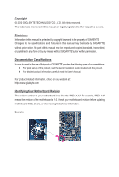
Motherboard GA-P67A-UD3/GA-PH67A-UD3/GA-PH67-UD3 Oct. 26, 2010 Motherboard GA-P67A-UD3/ GA-PH67A-UD3/ GA-PH67-UD3 Oct. 26, 2010 - Gigabyte GA-P67A-UD3 | Manual - Page 3
at: http://www.gigabyte.com Identifying Your Motherboard Revision The revision number on your motherboard looks like this: "REV: X.X." For example, "REV: 1.0" means the revision of the motherboard is 1.0. Check your motherboard revision before updating motherboard BIOS, drivers, or when looking - Gigabyte GA-P67A-UD3 | Manual - Page 4
Optional Items...6 GA-P67A-UD3/GA-PH67A-UD3/GA-PH67-UD3 Motherboard Layout 7 GA-P67A-UD3/GA-PH67A-UD3/GA-PH67-UD3 Motherboard Block Diagram 2 BIOS Setup 29 2-1 Startup Screen 30 2-2 The Main Menu 31 2-3 MB Intelligent Tweaker(M.I.T 33 2-4 Standard CMOS Features 41 2-5 Advanced BIOS Features - Gigabyte GA-P67A-UD3 | Manual - Page 5
55 3-1 Installing Chipset Drivers 55 3-2 Application Software 56 3-3 Technical Manuals 56 3-4 Contact...57 3-5 System...57 3-6 Download Center 58 3-7 New Utilities...58 Chapter 4 Unique Features 59 4-1 Xpress Recovery2 59 4-2 BIOS Update Utilities 62 4-2-1 Updating the BIOS with the Q-Flash - Gigabyte GA-P67A-UD3 | Manual - Page 6
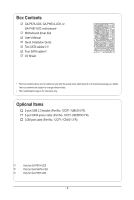
Box Contents GA-P67A-UD3, GA-PH67A-UD3, or GA-PH67-UD3 motherboard Motherboard driver disk User's Manual Quick Installation Guide Two SATA cableskl Four SATA cablesj I/O Shield • The box contents above are for reference only and the actual items shall depend on the product package - Gigabyte GA-P67A-UD3 | Manual - Page 7
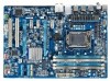
GA-P67A-UD3/GA-PH67A-UD3/GA-PH67-UD3 Motherboard Layout KB_MS_USB R_SPDIF ATX_12V_2X4 R_USB_2 LGA1155 PHASE LED R_USB_1 R_USB30 ATX USB_LAN Renesas D720200jk AUDIO Realtek RTL8111E CODEC SPDIF_O iTE IT8728 F_AUDIO SYS_FAN1 PCIEX1_1 (Note) BAT CPU_FAN GA-P67A-UD3/GA-PH67A-UD3/ PCIEX16 - Gigabyte GA-P67A-UD3 | Manual - Page 8
Interface 2 USB 3.0/2.0jk Renesas D720200 OR x4 x1 1 PCI Express x1 x1 PCI Express Bus Dual BIOS Switch Intel® P67j x1 Intel® H67kl 4 SATA 3Gb/s PCI Express Bus x1 PCIe CLK (100 MHz PCI PCI CLK (33 MHz) j k l Only for GA-P67A-UD3 Only for GA-PH67A-UD3 Only for GA-PH67-UD3 - 8 - - Gigabyte GA-P67A-UD3 | Manual - Page 9
electrostatic discharge (ESD). Prior to installation, carefully read the user's manual and follow these procedures: • Prior to installation, do not remove you are uncertain about any installation steps or have a problem related to the use of the product, please consult a certified computer technician. - Gigabyte GA-P67A-UD3 | Manual - Page 10
Support for SATA RAID 0, RAID 1, RAID 5, and RAID 10 * When a RAID set is built across the SATA 6Gb/s and SATA 3Gb/s channels, the system performance of the RAID set may vary depending on the devices being con- nected. j k l Only for GA-P67A-UD3 Only for GA-PH67A-UD3 Only for GA-PH67-UD3 - Gigabyte GA-P67A-UD3 | Manual - Page 11
on the back panel.jk Internal w 1 x 24-pin ATX main power connector Connectors w 1 x 8-pin ATX 12V power connector w 2 x SATA 6Gb/s connectors w supported will depend on the CPU/system cooler you install. j k l Only for GA-P67A-UD3 Only for GA-PH67A-UD3 Only for GA-PH67-UD3 - Gigabyte GA-P67A-UD3 | Manual - Page 12
for Auto Green Support for eXtreme Hard Drive Support for ON/OFF Charge Support for Cloud OC Support for Q-Share Norton Internet Security (OEM version) Operating System w Support for Microsoft® Windows 7/Vista/XP Form Factor w ATX Form Factor; 30.5cm x 21.5cm * GIGABYTE reserves the right - Gigabyte GA-P67A-UD3 | Manual - Page 13
and CPU Cooler Read the following guidelines before you begin to install the CPU: • Make sure that the motherboard supports the CPU. (Go to GIGABYTE's website for the latest CPU support list.) • Always turn off the computer and unplug the power cord from the power outlet before installing the CPU - Gigabyte GA-P67A-UD3 | Manual - Page 14
B. Follow the steps below to correctly install the CPU into the motherboard CPU socket. Before installing the CPU, make sure to turn off the computer and unplug the power cord from the power outlet to prevent damage to the CPU. Step 1: Gently press the CPU socket lever handle down and away from the - Gigabyte GA-P67A-UD3 | Manual - Page 15
" when pushing down each push pin. Check that the Male and Female push pins are joined closely. (Refer to your CPU cooler installation manual for instructions on installing the cooler.) Step 5: After the installation, check the back of the motherboard. If the push pin is inserted as the picture - Gigabyte GA-P67A-UD3 | Manual - Page 16
capacity, brand, speed, and chips be used. (Go to GIGABYTE's website for the latest supported memory speeds and memory modules.) • Always turn off the computer and DDR3 memory sockets and supports Dual Channel Technology. After the memory is installed, the BIOS will automatically detect the - Gigabyte GA-P67A-UD3 | Manual - Page 17
1-4-2 Installing a Memory Before installing a memory module, make sure to turn off the computer and unplug the power cord from the power outlet to prevent damage to the memory module. DDR3 and DDR2 DIMMs are not compatible to each other or DDR DIMMs. Be sure to install DDR3 DIMMs on this motherboard - Gigabyte GA-P67A-UD3 | Manual - Page 18
an expansion card: • Make sure the motherboard supports the expansion card. Carefully read the manual that came with your expansion card. • Always . If necessary, go to BIOS Setup to make any required BIOS changes for your expansion card(s). 7. Install the driver provided with the expansion card - Gigabyte GA-P67A-UD3 | Manual - Page 19
This connector provides digital audio out to an external audio system that supports digital optical audio. Before using this feature, ensure that your audio receiving is occurring j k l Only for GA-P67A-UD3 Only for GA-PH67A-UD3 Only for GA-PH67-UD3 • When removing the cable connected to a - Gigabyte GA-P67A-UD3 | Manual - Page 20
to perform different functions via the audio software. Only microphones still MUST be connected to the default Mic in jack ( ). Refer to the instructions on setting up a 2/4/5.1/7.1-channel audio configuration in Chapter 5, "Configuring 2/4/5.1/7.1-Channel Audio." Hardware Installation - 20 - - Gigabyte GA-P67A-UD3 | Manual - Page 21
1-7 Internal Connectors 14 3 15 2 6 11 7 8 10 13 4 1) ATX_12V_2X4 2) ATX 3) CPU_FAN 4) SYS_FAN1/SYS_FAN2 5) PWR_FAN 6) BAT 7) SATA3_0/1 8) SATA2_2/3/4/5 5 12 14 9 9) F_PANEL 10) F_AUDIO 11) SPDIF_O 12) F_USB1/F_USB2 13) COMA 14) CLR_CMOS 15) PHASE_LED Read the - Gigabyte GA-P67A-UD3 | Manual - Page 22
) 2 GND (Only for 2x4-pin 12V) 3 GND 4 GND 5 +12V (Only for 2x4-pin 12V) 6 +12V (Only for 2x4-pin 12V) 7 +12V 8 +12V 12 24 1 13 ATX ATX: Pin No. 1 2 3 4 5 6 7 8 9 10 11 12 Definition Pin No. 3.3V 13 3.3V 14 GND 15 +5V 16 GND 17 +5V 18 GND 19 Power Good 20 - Gigabyte GA-P67A-UD3 | Manual - Page 23
correct orientation (the black connector wire is the ground wire). The motherboard supports CPU fan speed control, which requires the use of a CPU fan (Battery) The battery provides power to keep the values (such as BIOS configurations, date, and time information) in the CMOS when the computer is - Gigabyte GA-P67A-UD3 | Manual - Page 24
supports a single SATA device.The SATA3_0 and SATA3_1 connectors support instructions on configuring a RAID array. 1 SATA2_2 SATA2_4 Pin No. 1 7 SATA2_3 2 3 4 SATA2_5 5 6 7 Definition GND TXP TXN GND RXN RXP GND j k l Only for GA-P67A-UD3 Only for GA-PH67A-UD3 Only for GA-PH67-UD3 - Gigabyte GA-P67A-UD3 | Manual - Page 25
a beep code. One single short beep will be heard if no problem is detected at system startup. If a problem is detected, the BIOS may issue beeps in different patterns to indicate the problem. Refer to Chapter 5, "Troubleshooting," for information about beep codes. • HD (Hard Drive Activity LED, Blue - Gigabyte GA-P67A-UD3 | Manual - Page 26
• The front panel audio header supports HD audio by default. If your chassis provides an AC'97 DB_PORTfront panel audio module, refer to the instructions on how to activate AC'97 digital audio cable, carefully read the manual for your expansion card. Pin No. Definition 1 SPDIFO 1 2 GND Hardware - Gigabyte GA-P67A-UD3 | Manual - Page 27
DY+ 7 GND 8 GND 9 No Pin 10 NC When the system is in S4/S5 mode, only the USB ports routed to the F_USB1 header can support the ON/OFF Charge function. • Do not plug the IEEE 1394 bracket (2x5-pin) cable into the USB header. • Prior to installing the USB bracket - Gigabyte GA-P67A-UD3 | Manual - Page 28
so may cause damage to the motherboard. • After system restart, go to BIOS Setup to load factory defaults (select Load Optimized Defaults) or manually configure the BIOS settings (refer to Chapter 2, "BIOS Setup," for BIOS configurations). 15) PHASE LED The number of lighted LEDs indicates the CPU - Gigabyte GA-P67A-UD3 | Manual - Page 29
latest version of BIOS from the Internet and updates the BIOS. For instructions on using the Q-Flash and @BIOS utilities, refer to Chapter 4, "BIOS Update Utilities." • Because BIOS flashing is potentially risky, if you do not encounter problems using the current version of BIOS, it is recommended - Gigabyte GA-P67A-UD3 | Manual - Page 30
P67A-UD3 F4g . . . . : BIOS Setup : XpressRecovery2 : Boot Menu : Qflash 11/17/2010-P67-7A89UG09C-00 Function Keys Function Keys: : POST SCREEN Press the key to show the BIOS POST screen. To show the BIOS POST screen at system startup, refer to the instructions - Gigabyte GA-P67A-UD3 | Manual - Page 31
and press to accept or enter a sub-menu. (Sample BIOS Version: GA-P67A-UD3 F4g) CMOS Setup Utility-Copyright (C) 1984-2010 Award Software MB Intelligent Tweaker(M.I.T.) Standard CMOS Features Advanced BIOS Features Integrated Peripherals Power Management Setup PC Health Status - Gigabyte GA-P67A-UD3 | Manual - Page 32
settings from a profile created before, without the hassles of reconfiguring the BIOS settings. First select the profile you wish to load, then press to complete. MB Intelligent Tweaker(M.I.T.) Use this menu to configure the clock, frequency and voltages of your CPU, memory, etc - Gigabyte GA-P67A-UD3 | Manual - Page 33
] Item Help Menu Level BIOS Version BCLK CPU Frequency Memory Frequency .80 MHz 3094.12 MHz 1064.51 MHz 2048 MB 31oC 1.236V 1.536V Move Enter: Select F5: the overclock/overvoltage settings you made is dependent on your overall system configurations. Incorrectly doing overclock/ - Gigabyte GA-P67A-UD3 | Manual - Page 34
you to alter the clock ratio for the installed CPU. The adjustable range is dependent on the CPU being installed. j Only for GA-P67A-UD3 (Note 1) This item is present only if you install a memory module that supports this feature. (Note 2) This item is present only if you install a CPU that - Gigabyte GA-P67A-UD3 | Manual - Page 35
. Set this item to Disabled if you want to manually configure CPU Turbo ratios in BIOS setup. (Default: Disabled) Intel(R) Turbo Boost Tech. BIOS automatically configure this setting. (Default: Auto) j (Note) Only for GA-P67A-UD3 This item is present only if you install a CPU that supports - Gigabyte GA-P67A-UD3 | Manual - Page 36
If your system fails to boot after overclocking, please wait for 20 seconds to allow DMI/PEG Frequency(0.1MHz) Allows you to manually set the CPU base clock and DMI/PCIe Note 2) Allows the BIOS to read the SPD only if you install a CPU that supports this feature. For more information about - Gigabyte GA-P67A-UD3 | Manual - Page 37
memory to increase memory performance and stability. Auto lets the BIOS automatically configure this setting. (Default: Auto) Rank Interleaving of the memory to increase memory performance and stability. Auto lets the BIOS automatically configure this setting. (Default: Auto) (Note) This item - Gigabyte GA-P67A-UD3 | Manual - Page 38
), 1~16. tWTP Options are: Auto (default), 1~31. tWL Options are: Auto (default), 1~12 tRFC Options are: Auto (default), 1~255. tRTP Options are: Auto (default), 1~15. BIOS Setup - 38 - - Gigabyte GA-P67A-UD3 | Manual - Page 39
is set to Normal. The default is Auto. QPI/Vtt Voltage The default is Auto. System Agent Voltage The default is Auto. >>> MCH/ICH - 39 - BIOS Setup - Gigabyte GA-P67A-UD3 | Manual - Page 40
2010 Award Software Miscellaneous Settings Isochronous Support Virtualization Technology (Note) [Enabled General Help F7: Optimized Defaults Isochronous Support Determines whether to enable specific streams within you install a CPU that supports this feature. For more information about - Gigabyte GA-P67A-UD3 | Manual - Page 41
the detection of the device during the POST for faster system startup. • Auto Lets the BIOS automatically detect SATA devices during the POST. (Default) • Manual Allows you to manually enter the specifications of the hard drive when the hard drive access mode is set to - Gigabyte GA-P67A-UD3 | Manual - Page 42
hard drive specifications. If you wish to enter the parameters manually, refer to the information on the hard drive. Capacity whether the system will stop for an error during the POST. All Errors Whenever the BIOS detects a non-fatal error the system boot will stop. No Errors The system boot - Gigabyte GA-P67A-UD3 | Manual - Page 43
time the system boots, or only when you enter BIOS Setup. After configuring this item, set the password(s) under the Set Supervisor/User Password item This item is present only if you install a CPU that supports this feature. For more information about Intel CPUs' unique features, please visit Intel's website - Gigabyte GA-P67A-UD3 | Manual - Page 44
HDD (Secs) Allows you to set a delay time for the BIOS to initialize the hard drive as the system boots up. The Show Allows you to determine whether to display the GIGABYTE Logo at system startup. Disabled displays normal POST supports this feature. For more information about Intel CPUs' unique - Gigabyte GA-P67A-UD3 | Manual - Page 45
support Native mode. Enabled Allows the SATA controllers to operate in Native IDE mode. Enable Native IDE mode if you wish to install operating systems that support Native mode. (Default) j k l Only for GA-P67A-UD3 Only for GA-PH67A-UD3 Only for GA-PH67-UD3 - 45 - BIOS - Gigabyte GA-P67A-UD3 | Manual - Page 46
Length fields show 0m, as shown in the figure above. When LAN Cable Is Functioning Normally... If no cable problem is detected on the LAN cable connected to a Gigabit hub or a 10/100 Mbps hub, the following message 1000 Mbps in Windows mode or when the LAN Boot ROM is activated. BIOS Setup - 46 - - Gigabyte GA-P67A-UD3 | Manual - Page 47
When a Cable Problem Occurs... If a cable problem occurs on a specified pair of wires, the Status field will show Short and then length interrupt. Options are:Auto, 3F8/IRQ4 (default), 2F8/IRQ3, 3E8/IRQ4, 2E8/IRQ3, Disabled. j Only for GA-P67A-UD3 k Only for GA-PH67A-UD3 - 47 - BIOS Setup - Gigabyte GA-P67A-UD3 | Manual - Page 48
from a PCI or PCIe device. Note: To use this function, you need an ATX power supply providing at least 1A on the +5VSB lead. (Default: Enabled) Power signal from a modem that supports wake-up function. (Default: Enabled) (Note) Supported on Windows 7/Vista operating system only. BIOS Setup - 48 - - Gigabyte GA-P67A-UD3 | Manual - Page 49
effective. HPET Support (Note) Enables only when the HPET Support is set to Enabled. function, you need an ATX power supply providing at least . Note: you need an ATX power supply providing at least AC power. ErP Support Determines whether to let Supported on Windows 7/Vista operating system only. - 49 - Gigabyte GA-P67A-UD3 | Manual - Page 50
to Enabled, save the settings to the CMOS, and then restart your system. Current Voltage(V) Vcore/DDR15V/+12V/Vcc3/Vtt Displays the current system voltages. BIOS Setup - 50 - - Gigabyte GA-P67A-UD3 | Manual - Page 51
. (Default) Silent Allows the CPU fan to run at slow speeds. Manual Allows you to control the CPU fan speed under the Slope PWM item. only when CPU Smart FAN Control is set to Enabled. Auto Lets the BIOS automatically detect the type of CPU fan installed and sets the optimal CPU fan - Gigabyte GA-P67A-UD3 | Manual - Page 52
F11: Save CMOS to BIOS F12: Load CMOS from BIOS Press on this item and then press the key to load the optimal BIOS default settings. The BIOS defaults settings help the system to operate in optimum state. Always load the Optimized defaults after updating the BIOS or after clearing the - Gigabyte GA-P67A-UD3 | Manual - Page 53
2-11 Set Supervisor/User Password CMOS Setup Utility-Copyright (C) 1984-2010 Award Software MB Intelligent Tweaker(M.I.T.) Standard CMOS Features Advanced BIOS Features Integrated Peripherals Power Management SetupEnter Password: PC Health Status Load Fail-Safe Defaults Load Optimized - Gigabyte GA-P67A-UD3 | Manual - Page 54
2-12 Save & Exit Setup CMOS Setup Utility-Copyright (C) 1984-2010 Award Software MB Intelligent Tweaker(M.I.T.) Load Fail-Safe Defaults Standard CMOS Features Advanced BIOS Features Load Optimized Defaults Save to CMOS and EXITSe(Yt S/Nup)?erYvisor Password Integrated Peripherals Set - Gigabyte GA-P67A-UD3 | Manual - Page 55
install new GIGABYTE utilities. Click Yes to automatically install the utilities. Or click No if you want to manually select the utilities to install on the Application Software page later. • For USB 2.0 driver support under the Windows XP operating system, please install the Windows XP Service Pack - Gigabyte GA-P67A-UD3 | Manual - Page 56
applications that GIGABYTE develops and some free software. You can click the Install button on the right of an item to install it. 3-3 Technical Manuals This page provides GIGABYTE's application guides, content descriptions for this driver disk, and the motherboard manuals. Drivers Installation - Gigabyte GA-P67A-UD3 | Manual - Page 57
3-4 Contact For the detailed contact information of the GIGABYTE Taiwan headquarter or worldwide branch offices, click the URL on this page to link to the GIGABYTE website. 3-5 System This page provides the basic system information. - 57 - Drivers Installation - Gigabyte GA-P67A-UD3 | Manual - Page 58
3-6 Download Center To update the BIOS, drivers, or applications, click the Download Center button to link to the GIGABYTE website. The latest version of the BIOS, drivers, or applications will be displayed. 3-7 New Utilities This page provides a quick link to GIGABYTE's lately developed utilities - Gigabyte GA-P67A-UD3 | Manual - Page 59
system data and perform restoration of it. Supporting NTFS, FAT32, and FAT16 file systems, your system soon after the operating system and drivers are installed. • The amount of data and hard to restore it. System Requirements: • At least 512 MB of system memory • VESA compatible graphics card • - Gigabyte GA-P67A-UD3 | Manual - Page 60
note that if there is no enough unallocated space, Xpress Recovery2 cannot save the backup file. B. Accessing Xpress Recovery2 1. Boot from the motherboard driver disk to access Xpress Recovery2 for the first time. When you see the following message: Press any key to startup Xpress Recovery2, press - Gigabyte GA-P67A-UD3 | Manual - Page 61
D. Using the Restore Function in Xpress Recovery2 Select RESTORE to restore the backup to your hard drive in case the system breaks down. The RESTORE option will not be present if no backup is created before. E. Removing the Backup Step 1: If you wish to remove the backup file, select REMOVE. Step - Gigabyte GA-P67A-UD3 | Manual - Page 62
, if the BIOS update file is saved to a hard drive in RAID/AHCI mode or a hard drive attached to an independent SATA controller, use the key during the POST to access Q-Flash. Award Modular BIOS v6.00PG Copyright (C) 1984-2010, Award Software, Inc. P67A-UD3 F4g . . . . : BIOS Setup - Gigabyte GA-P67A-UD3 | Manual - Page 63
the up or down arrow key to select Update BIOS from Drive and press . • The Save Main BIOS to Drive option allows you to save the current BIOS file. • Q-Flash only supports USB flash drive or hard drives using FAT32/16/12 file system. • If the BIOS update file is saved to a hard drive in RAID - Gigabyte GA-P67A-UD3 | Manual - Page 64
Defaults and press to load BIOS defaults. System will re-detect all peripheral devices after a BIOS update, so we recommend that you reload BIOS defaults. CMOS Setup Utility-Copyright (C) 1984-2010 Award Software MB Intelligent Tweaker(M.I.T.) Load Fail-Safe Defaults Standard - Gigabyte GA-P67A-UD3 | Manual - Page 65
on the @BIOS server site, please manually download the BIOS update file from GIGABYTE's website and follow the instructions in "Update the BIOS without Using the Internet Update Function" below. 2. Update the BIOS without Using the Internet Update Function: Click Update BIOS from File, then - Gigabyte GA-P67A-UD3 | Manual - Page 66
GIGABYTE's EasyTune 6 is a simple and easy-to-use interface that allows users to fine-tune their system settings or do overclock/ that the item is not configurable or the function is not supported. Incorrectly doing overclock/overvoltage may result in damage to the hardware components such - Gigabyte GA-P67A-UD3 | Manual - Page 67
hardware and software design, GIGABYTE Dynamic Energy Saver™ 2 Energy Saver™ 2 Interface A. Meter Mode In Meter Mode, GIGABYTE Dynamic Energy Saver™ 2 shows how much power they have saved LED On/Off Switch (Default: On) 16 Live Utility Update (Check for the latest utility version) • The above - Gigabyte GA-P67A-UD3 | Manual - Page 68
Phase LED On/Off Switch (Default: On) 15 Live Utility Update (Check for the latest utility version) C. Stealth Mode In Stealth function, make sure the CPU Enhanced Halt (C1E) and CPU EIST Function items in the BIOS Setup program are set to Enabled. (Note 2) 1: Smart FAN/CPU (default); 2: - Gigabyte GA-P67A-UD3 | Manual - Page 69
using Q-Share After installing Q-Share from the motherboard driver disk, go to Start>All Programs>GIGABYTE>Q-Share. exe to launch the Q-Share tool. Find shared data folder Changes the data folder to be shared (Note) Updates Q-Share online Displays the current Q-Share version Exits Q-Share ( - Gigabyte GA-P67A-UD3 | Manual - Page 70
Smart 6™ GIGABYTE Smart 6™ ( efficiency for daily use. Instructions: Select the Enable check box below the BIOS QuickBoot or OS QuickBoot item and then click Save to save the settings. SMART QuickBoost SMART QuickBoost features quick and effortless CPU overclocking - Gigabyte GA-P67A-UD3 | Manual - Page 71
your files from the backup image System Recovery... Allows you to recover your system from the backup image • Supported operating systems: Windows 7 and Vista. • Smart Recovery 2 only supports NTFS file system. • You need to select the destination partition in Settings the first time you use Smart - Gigabyte GA-P67A-UD3 | Manual - Page 72
, and remind users of the dates. It also stores the recorded data in the main and backup BIOS simultaneously, which can prevent loss of the data in case the system/hard drive fails. Instructions: Enter the Smart 6™ password to launch the SMART DualBIOS utility. You can record personal passwords and - Gigabyte GA-P67A-UD3 | Manual - Page 73
were moved within the hard drive or copied to an external storage device (Note 2). Instructions: Select the Enable check box at the bottom of the ON/OFF Recorder or File the User Password in the system BIOS Setup program to prevent the system time being changed by other users. - 73 - Unique - Gigabyte GA-P67A-UD3 | Manual - Page 74
4-7 Auto Green Auto Green is an easy-to-use tool that provides users with simple options to enable system power savings via a Bluetooth cell phone. When the phone is out of the range of the computer's Bluetooth receiver, the system will enter the specified power saving mode. The Configuration dialog - Gigabyte GA-P67A-UD3 | Manual - Page 75
All button to automatically install all motherboard drivers, including the X.H.D utility. Or you can go to the Application Software screen to individually install the X.H.D utility later. B. Using GIGABYTE eXtreme Hard Drive (X.H.D) Instructions: (Note 2) Before launching X.H.D, make sure the newly - Gigabyte GA-P67A-UD3 | Manual - Page 76
Cloud OC (Note 1) is an easy-to-use overclocking utility designed for system overclocking via virtually any Internet-connected device, such as . (Note 1) (Note 2) (Note 3) Supported on Windows 7, Vista, and XP. For Windows XP, be sure to update Internet Explorer to version 7.0 or later. When - Gigabyte GA-P67A-UD3 | Manual - Page 77
mode in BIOS Setup. C. Configure a RAID array in RAID BIOS. (Note 1) D. Install the SATA RAID/AHCI driver (Note supported by the P67j/H67kl Chipset.) Then connect the power connector from your power supply to the hard drive. j Only for GA-P67A-UD3 k Only for GA-PH67A-UD3 l Only for GA-PH67-UD3 - Gigabyte GA-P67A-UD3 | Manual - Page 78
correctly in system BIOS Setup. Step 1: Turn on your computer and press to enter BIOS Setup during the POST (Power-On Self-Test). To create Step 2: Save changes and exit BIOS Setup. j k Only for GA-P67A-UD3 Only for GA-PH67A-UD3 The BIOS Setup menus described in this section may - Gigabyte GA-P67A-UD3 | Manual - Page 79
C. Configuring a RAID array in RAID BIOS Enter the RAID BIOS setup utility to configure a RAID array. Skip this step and proceed with the installation of Windows operating system for a non-RAID configuration. Step 1: After the POST memory test begins and before the operating system boot begins, - Gigabyte GA-P67A-UD3 | Manual - Page 80
with 1~16 letters (letters cannot be special characters) under the Name item and press . Then, select a RAID level (Figure 4). RAID levels supported include RAID 0, RAID 1, Recovery, RAID 10, and RAID 5 (the selections available depend on the number of the hard drives being installed). Press - Gigabyte GA-P67A-UD3 | Manual - Page 81
] Name : Volume0 RAID Level : RAID0(Stripe) Disks : Select Disks Strip Size : 128 MB Capacity : 111.7 GB Sync : N/A Create Volume WARNING : ALL DATA ON SELECTED DISKS WILL ]-Exit Figure 7 [ENTER]-Select Menu To exit the RAID BIOS utility, press or select 5. Exit in MAIN MENU. Now, you - Gigabyte GA-P67A-UD3 | Manual - Page 82
Recovery Volume Options Intel Rapid Recover Technology provides data protection by allowing users to easily restore data and system operation using a designated recovery drive. With the Rapid Recovery Technology, which employs RAID 1 functionality, users can copy the data from the master drive to - Gigabyte GA-P67A-UD3 | Manual - Page 83
. On Request allows users to update data from the master drive to the recovery drive manually using the Intel Rapid Storage Technology ] Select a sync option: On Request: volume is updated manually Continuous: volume is updated automatically [hi]-Change [TAB]-Next [ESC]-Previous Menu Figure - Gigabyte GA-P67A-UD3 | Manual - Page 84
Delete RAID Volume To delete a RAID array, select Delete RAID Volume in MAIN MENU and press . In the DELETE VOLUME MENU section, use the up or down arrow key to select the array to be deleted and press . When prompted to confirm your selection (Figure 12), press to confirm or - Gigabyte GA-P67A-UD3 | Manual - Page 85
Driver and Operating System With the correct BIOS settings, you are ready to install Windows 7/Vista/XP onto your hard drive(s). A. Installing Windows XP To install Windows XP, you need to install the SATA RAID/AHCI controller driver with Windows, using a device support disk provided by an adapter - Gigabyte GA-P67A-UD3 | Manual - Page 86
notification area, which will show that a RAID volume is being rebuilt). If you do not enable automatic rebuild on this stage, you have to manually rebuild the array in the operating system (see the next page for more details). Intel(R) Rapid Storage Technology - Option ROM - 10.0.0.1046 Copyright - Gigabyte GA-P67A-UD3 | Manual - Page 87
• Performing the Rebuild in the Operating System While in the operating system, make sure the chipset driver has been installed from the motherboard driver disk. Then launch the Intel Rapid Storage Technology utility from All Programs in the Start menu. Step 1: Go to the Manage menu and click - Gigabyte GA-P67A-UD3 | Manual - Page 88
Recovery Volume only) When two hard drives are set to Recovery Volume in Update on Request mode, you can restore the master drive data to the last the recovery drive in the operating system. Follow the on-screen instructions to complete and exit the RAID Configuration Utility. Intel(R) Rapid - Gigabyte GA-P67A-UD3 | Manual - Page 89
audio driver. For manually configure the jack for microphone functionality. • Audio signals will be present on both of the front and back panel audio connections simultaneously. If you want to mute the back panel audio (only supported when using an HD front panel audio module), refer to instructions - Gigabyte GA-P67A-UD3 | Manual - Page 90
Step 2: Connect an audio device to an audio jack. The The current connected device is dialog box appears. Select the device according to the type of device you connect. Then click OK. Step 3: On the Speakers screen, click the Speaker Configuration tab. In the Speaker Configuration list, select - Gigabyte GA-P67A-UD3 | Manual - Page 91
5-2-2 Configuring S/PDIF Out The S/PDIF Out jacks (Note 1) can transmit audio signals to an external decoder for decoding to get the best audio quality. 1. Connecting a S/PDIF Out Cable: S/PDIF Coaxial Cable S/PDIF Optical Cable Connect a S/PDIF coaxial cable or a S/PDIF optical cable (either one - Gigabyte GA-P67A-UD3 | Manual - Page 92
5-2-3 Configuring Microphone Recording Step 1: After installing the audio driver, the HD Audio Manager icon will appear in the notification area. Double-click the icon to access the HD Audio Manager. Step 2: Connect your microphone - Gigabyte GA-P67A-UD3 | Manual - Page 93
Step 5: After completing the settings above, click Start, point to All Programs, point to Accessories, and then click Sound Recorder to begin the sound recording. * Enabling Stereo Mix If the HD Audio Manager does not display the recording device you wish to use, refer to the steps below. The - Gigabyte GA-P67A-UD3 | Manual - Page 94
. Be sure to save the recorded audio file upon completion. B. Playing the Recorded Sound You can play your recording in a digital media player program that supports your audio file format. Appendix - 94 - - Gigabyte GA-P67A-UD3 | Manual - Page 95
GIGABYTE's website to install. For more details, go to the Support & Downloads\FAQ page on our website and search for "onboard HD audio driver." Q: What do the beeps emitted during the POST mean? A: The following Award BIOS beep code descriptions may help you identify possible computer problems - Gigabyte GA-P67A-UD3 | Manual - Page 96
If you encounter any troubles during system startup, follow the troubleshooting procedure below to solve the problem. START Turn off the the memory into the memory socket. Yes The problem is verified and solved. Insert the graphics card. Connect the ATX main power cable and the 12V power cable. - Gigabyte GA-P67A-UD3 | Manual - Page 97
"Save & Exit Setup" to save changes and exit BIOS Setup. The problem is verified and solved. Turn off the computer and connect problem, contact the place of purchase or local dealer for help. Or go to the Support & Downloads\Technical Support page to submit your question. Our customer service - Gigabyte GA-P67A-UD3 | Manual - Page 98
" product. Restriction of Hazardous Substances (RoHS) Directive Statement GIGABYTE products have not intended to add and safe from hazardous government office, your household waste disposal service or where you purchased the product manual and we will be glad to help you with your effort. - Gigabyte GA-P67A-UD3 | Manual - Page 99
Finally, we suggest that you practice other environmentally friendly actions by understanding and using the energy-saving features of this product (where applicable), recycling the inner and outer packaging (including shipping containers) this product was delivered in, and by disposing of or - Gigabyte GA-P67A-UD3 | Manual - Page 100
Appendix - 100 - - Gigabyte GA-P67A-UD3 | Manual - Page 101
- 101 - Appendix - Gigabyte GA-P67A-UD3 | Manual - Page 102
Appendix - 102 - - Gigabyte GA-P67A-UD3 | Manual - Page 103
231, Taiwan TEL: +886-2-8912-4000 FAX: +886-2-8912-4003 Tech. and Non-Tech. Support (Sales/Marketing) : http://ggts.gigabyte.com.tw WEB address (English): http://www.gigabyte.com WEB address (Chinese): http://www.gigabyte.tw • G.B.T. INC. - U.S.A. TEL: +1-626-854-9338 FAX: +1-626-854-9339 Tech - Gigabyte GA-P67A-UD3 | Manual - Page 104
, select your language in the language list on the top right corner of the website. • GIGABYTE Global Service System To submit a technical or non-technical (Sales/Marketing) question, please link to: http://ggts.gigabyte.com.tw Then select your language to enter the system. Appendix - 104 -
-
 1
1 -
 2
2 -
 3
3 -
 4
4 -
 5
5 -
 6
6 -
 7
7 -
8
-
9
-
10
-
11
-
12
-
13
-
14
-
15
-
16
-
17
-
18
-
19
-
20
-
21
-
22
-
23
-
24
-
25
-
26
-
27
-
28
-
29
-
30
-
31
-
32
-
33
-
34
-
35
-
36
-
37
-
38
-
39
-
40
-
41
-
42
-
43
-
44
-
45
-
46
-
47
-
48
-
49
-
50
-
51
-
52
-
53
-
54
-
55
-
56
-
57
-
58
-
59
-
60
-
61
-
62
-
63
-
64
-
65
-
66
-
67
-
68
-
69
-
70
-
71
-
72
-
73
-
74
-
75
-
76
-
77
-
78
-
79
-
80
-
81
-
82
-
83
-
84
-
85
-
86
-
87
-
88
-
89
-
90
-
91
-
92
-
93
-
94
-
95
-
96
-
97
-
98
-
99
-
100
-
101
-
102
-
103
-
104
 |
 |

GA-P67A-UD3
GA-PH67A-UD3
GA-PH67-UD3
LGA1155 socket motherboard for Intel
®
Core
™
i7 processors/
Intel
®
Core
™
i5 processors/Intel
®
Core
™
i3 processors/
Intel
®
Pentium
®
processors/Intel
®
Celeron
®
processors
User's Manual
Rev. 1002
12ME-P67AUD3-1002R