Gigabyte GA-Q35M-S2 Manual
Gigabyte GA-Q35M-S2 Manual
 |
View all Gigabyte GA-Q35M-S2 manuals
Add to My Manuals
Save this manual to your list of manuals |
Gigabyte GA-Q35M-S2 manual content summary:
- Gigabyte GA-Q35M-S2 | Manual - Page 1
GA-Q35M-S2 LGA775 socket motherboard for Intel® CoreTM processor family/ Intel® Pentium® processor family/Intel® Celeron® processor family User's Manual Rev. 1001 12ME-Q35MS2-1001R - Gigabyte GA-Q35M-S2 | Manual - Page 2
Motherboard GA-Q35M-S2 Nov. 21, 2007 Motherboard GA-Q35M-S2 Nov. 21, 2007 - Gigabyte GA-Q35M-S2 | Manual - Page 3
of documentations: „ For detailed product information, carefully read the User's Manual. „ For instructions on how to use GIGABYTE's unique features, read or download the information on/from the Support\Motherboard\Technology Guide page on our website. For product-related information, check on our - Gigabyte GA-Q35M-S2 | Manual - Page 4
...6 Box Contents ...6 GA-Q35M-S2 Motherboard Layout 7 Block Diagram ...8 Chapter 1 Hardware Installation 9 1-1 Installation Precautions 9 1-2 Product Specifications 10 1-3 Installing the CPU and CPU Cooler 13 1-3-1 Installing the CPU 13 1-3-2 Installing the CPU Cooler 15 1-4 Installing - Gigabyte GA-Q35M-S2 | Manual - Page 5
Driver CD Information 56 3-4 Hardware Information 57 3-5 Contact Us ...57 Chapter 4 Unique Features 59 4-1 Xpress Recovery2 59 4-2 BIOS Update Utilities 64 4-2-1 Updating the BIOS with the Q-Flash Utility 64 4-2-2 Updating the BIOS with the @BIOS Utility 67 4-3 EasyTune 5 Pro 69 4-4 Windows - Gigabyte GA-Q35M-S2 | Manual - Page 6
Box Contents GA-Q35M-S2 motherboard Motherboard driver disk User's Manual Intel® LGA775 CPU Installation Guide One IDE cable and one floppy disk drive cable Two SATA 3Gb/s cables I/O Shield • The box contents above are for reference only and the actual - Gigabyte GA-Q35M-S2 | Manual - Page 7
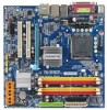
GA-Q35M-S2 Motherboard Layout KB_MS LGA775 CPU_FAN ATX IT8718 VGA COM LPT GA-Q35M-S2 R_USB FDD ATX_12V Intel® Q35 USB LAN1 F_AUDIO AUDIO PCIE_16 Nineveh 82566DM PCI1 PCI2 CD_IN PCIE_1 CODEC SPDIF_IO COMB DDRII1 DDRII2 DDRII3 DDRII4 TPM_CLR Intel® ICH9DO IDE JMicron 368 BATTERY - Gigabyte GA-Q35M-S2 | Manual - Page 8
Block Diagram PCIe CLK (100 MHz) D-Sub LGA775 Processor Host Interface PCI Express x16 LAN PCI Express x1 RJ45 PCIe CLK (100 MHz) x1 Nineveh 82566DM GLCI x1 PCI Express Bus ATA-133/100/66/33 IDE Channel JMicron 368 PCI Bus Intel® Q35 Intel® ICH9DO CODEC CPU CLK+/(333/266/200 MHz) DDR2 - Gigabyte GA-Q35M-S2 | Manual - Page 9
manual and follow these procedures: • Prior to installation, do not remove or break motherboard S/N (ESD) wrist strap when handling electronic components such as a motherboard, CPU or memory. If you do not have an ESD wrist steps or have a problem related to the use of the product, please consult - Gigabyte GA-Q35M-S2 | Manual - Page 10
/66/33 and up to 2 IDE devices Š iTE IT8718 chip: - 1 x floppy disk drive connector supporting up to 1 floppy disk drive Š Integrated in the South Bridge Š Up to 12 USB 2.0/1.1 ports (6 on the back panel, 6 via the USB brackets connected to the internal USB headers) GA-Q35M-S2 Motherboard - 10 - - Gigabyte GA-Q35M-S2 | Manual - Page 11
RJ-45 port Š 6 x audio jacks (Center/Subwoofer Speaker Out/Rear CPU/System temperature detection Š CPU/System fan speed detection Š CPU overheating warning Š CPU/System fan fail warning Š CPU fan speed control BIOS Š 1 x 8 Mbit flash Š Use of licensed AWARD BIOS Š PnP 1.0a, DMI 2.0, SM BIOS - Gigabyte GA-Q35M-S2 | Manual - Page 12
memory is installed, the actual memory size displayed will be less than 4 GB. (Note 2) Available functions in Easytune may differ by motherboard model. (Note 3) Due to chipset limitation, Intel ICH9DO RAID driver does not support Windows 2000 operating system. GA-Q35M-S2 Motherboard - 12 - - Gigabyte GA-Q35M-S2 | Manual - Page 13
so according to your hardware specifications including the CPU, graphics card, memory, hard drive, etc. 1-3-1 Installing the CPU A. Locate the alignment keys on the motherboard CPU socket and the notches on the CPU. LGA775 CPU Socket Alignment Key LGA 775 CPU Alignment Key Pin One Corner of the - Gigabyte GA-Q35M-S2 | Manual - Page 14
pin one corner of the CPU socket (or you may align the CPU notches with the socket alignment keys) and gently insert the CPU into position. Step 5: Once the CPU is properly inserted, replace the load plate and push the CPU socket lever back into its locked position. GA-Q35M-S2 Motherboard - 14 - - Gigabyte GA-Q35M-S2 | Manual - Page 15
. Check that the Male and Female push pins are joined closely. (Refer to your CPU cooler installation manual for instructions on installing the cooler.) Step 5: After the installation, check the back of the motherboard. If the push pin is inserted as the picture above, the installation is complete - Gigabyte GA-Q35M-S2 | Manual - Page 16
Dual Channel Memory Configuration This motherboard provides four DDR2 memory sockets and supports Dual Channel Technology. After the memory is installed, the BIOS will automatically detect the specifications to be populated and remain in Dual Channel mode/performance. GA-Q35M-S2 Motherboard - 16 - - Gigabyte GA-Q35M-S2 | Manual - Page 17
to each other or DDR DIMMs. Be sure to install DDR3 DIMMs on this motherboard. Notch DDR2 DIMM A DDR2 memory module has a notch, so it can only Spread the retaining clips at both ends of the memory socket. Place the memory module on the socket. As indicated in the picture on the left, place - Gigabyte GA-Q35M-S2 | Manual - Page 18
expansion card: • Make sure the motherboard supports the expansion card. Carefully read the manual that came with your expansion card. necessary, go to BIOS Setup to make any required BIOS changes for your expansion card(s). 7. Install the driver provided with the GA-Q35M-S2 Motherboard - 18 - - Gigabyte GA-Q35M-S2 | Manual - Page 19
is occurring On No data transmission or receiving is occurring Off LAN link is not established • When removing the cable connected to a back panel connector, first remove the cable from your device and then remove it from the motherboard. • When removing the cable, pull it straight out from the - Gigabyte GA-Q35M-S2 | Manual - Page 20
to perform different functions via the audio software. Only microphones still MUST be connected to the default Mic in jack ( ). Refer to the instructions on setting up a 2/4/5.1/ 7.1-channel audio configuration in Chapter 5, "Configuring 2/4/5.1/7.1-Channel Audio." GA-Q35M-S2 Motherboard - 20 - - Gigabyte GA-Q35M-S2 | Manual - Page 21
ATX 3) CPU_FAN 4) SYS_FAN 5) FDD 6) IDE 7) SATAII0 / 1 / 2 / 3 / 4 / 5 8) PWR_LED 9) BATTERY 10) F_PANEL 11) F_AUDIO 12) CD_IN 13) SPDIF_IO 14) F_USB1 / F_USB2 / F_USB3 15) COMB 16) CLR_CMOS 17) CI 18) has been securely attached to the connector on the motherboard. - 21 - Hardware Installation - Gigabyte GA-Q35M-S2 | Manual - Page 22
. The 12V power connector mainly supplies power to the CPU. If the 12V power connector is not connected, the +12V 8 +12V 12 24 1 13 ATX ATX: Pin No. 1 2 3 4 5 6 7 8 9 10 11 12 Definition Pin No. 3.3V 13 3.3V 14 GND 15 +5V 16 GND 17 +5V 18 GND 19 GA-Q35M-S2 Motherboard - 22 - - Gigabyte GA-Q35M-S2 | Manual - Page 23
wire indicates a positive connection and requires a +12V voltage. The black connector wire is the ground wire. The motherboard supports CPU fan speed control, which requires the use of a CPU fan with fan speed control design. For optimum heat dissipation, it is recommended that a system fan be - Gigabyte GA-Q35M-S2 | Manual - Page 24
even number. • A RAID 5 configuration requires at least three hard drives. (The total number of hard drives does not have to be an even number.) • A RAID 10 configuration requires at least four hard drives and the total number of hard drives must be an even number. GA-Q35M-S2 Motherboard - 24 - - Gigabyte GA-Q35M-S2 | Manual - Page 25
MPD- 1 3 MPD- System Status LED S0 On S1 Blinking S3/S4/S5 Off 9) BATTERY The battery provides power to keep the values (such as BIOS configurations, date, and time information) in the CMOS when the computer is turned off. Replace the battery when the battery voltage drops to a low level - Gigabyte GA-Q35M-S2 | Manual - Page 26
10) F_PANEL (Front Panel Header) if no problem is detected at system startup. If a problem is detected, the BIOS may issue beeps in different patterns to indicate the problem. Refer to Chapter 5, "Troubleshooting," for information pin assignments are matched correctly. GA-Q35M-S2 Motherboard - 26 - - Gigabyte GA-Q35M-S2 | Manual - Page 27
Out (L) 10 GND 10 NC • The front panel audio header supports HD audio by default. If your chassis provides an AC'97 front panel audio module, refer to the instructions on how to activate AC'97 functioninality via the audio software in Chapter 5, "Configuring 2/4/5.1/7.1-Channel Audio." • When - Gigabyte GA-Q35M-S2 | Manual - Page 28
7 GND 8 GND 9 No Pin 10 NC • Do not plug the IEEE 1394 bracket (2x5-pin) cable into the USB header. • Prior to installing the USB bracket, be sure to turn off your computer and unplug the power cord from the power outlet to prevent damage to the USB bracket. GA-Q35M-S2 Motherboard - 28 - - Gigabyte GA-Q35M-S2 | Manual - Page 29
contact the local dealer. 2 10 1 9 Pin No. 1 2 3 4 5 6 7 8 9 10 Definition NDCD BNSIN B NSOUT B motherboard. • After system restart, go to BIOS Setup to load factory defaults (select Load Optimized Defaults) or manually configure the BIOS settings (refer to Chapter 2, "BIOS Setup," for BIOS - Gigabyte GA-Q35M-S2 | Manual - Page 30
2 GND 18) TPM_CLR (TPM_PHYSICAL_PRESENCE) Pin No. Definition 1 1 GND 2 TPM_PP 3 Power TPM_CLR 1-2 short 2-3 short Force_Clear command Supports the Hardware/Software physical presence function. (Default) Supports the Hardware physical presence function. GA-Q35M-S2 Motherboard - 30 - - Gigabyte GA-Q35M-S2 | Manual - Page 31
19) SPI_FLASH Open: Enables the iAMT function. (Default) Short: Disables the iAMT function. - 31 - Hardware Installation - Gigabyte GA-Q35M-S2 | Manual - Page 32
GA-Q35M-S2 Motherboard - 32 - - Gigabyte GA-Q35M-S2 | Manual - Page 33
Windows-based utility that searches and downloads the latest version of BIOS from the Internet and updates the BIOS. For instructions on using the Q-Flash and @BIOS utilities, refer to Chapter 4, "BIOS Update Utilities." • Because BIOS flashing is potentially risky, if you do not encounter problems - Gigabyte GA-Q35M-S2 | Manual - Page 34
Motherboard Model BIOS Version Award Modular BIOS v6.00PG, An Energy Star Ally Copyright (C) 1984-2007, Award Software, Inc. Intel Q35 BIOS for Q35M-S2 F1a . . . . : BIOS directly without having to enter BIOS Setup first. Intel ME Setup: After the POST memory test begins and before the - Gigabyte GA-Q35M-S2 | Manual - Page 35
among the items and press to accept or enter a sub-menu. (Sample BIOS Version: F1a) CMOS Setup Utility-Copyright (C) 1984-2007 Award Software ` Standard CMOS Features ` Advanced BIOS Features ` Integrated Peripherals ` Power Management Setup ` PnP/PCI Configurations ` PC Health Status - Gigabyte GA-Q35M-S2 | Manual - Page 36
Saving Abandon all changes and the previous settings remain in effect. Pressing to the confirmation message will exit BIOS Setup. (Pressing can also carry out this task.) „ Security Chip Configuration Use this menu to configure the TPM module function. GA-Q35M-S2 Motherboard - 36 - - Gigabyte GA-Q35M-S2 | Manual - Page 37
Help F7: Optimized Defaults Extended Memory Total Memory CMOS Setup Utility-Copyright (C) 1984-2007 Award Software Standard CMOS Features 510M 512M Item Help Menu Level` KLJI: Move Enter: Select F5: Previous IDE/SATA device on this channel. IDE Channel 0, 1 Master/Slave - 37 - BIOS Setup - Gigabyte GA-Q35M-S2 | Manual - Page 38
-only and are determined by the BIOS POST. Base Memory Also called conventional memory. Typically, 640 KB will be reserved for the MS-DOS operating system. Extended Memory The amount of extended memory. Total Memory The total amount of memory installed on the system. GA-Q35M-S2 Motherboard - 38 - - Gigabyte GA-Q35M-S2 | Manual - Page 39
Monitor 2(TM2) (Note) CPU EIST Function (Note) Virtualization Technology (Note) Console Redirection x Baud Rate [Disabled] [Disabled] [Enabled] [Enabled] [Enabled] [Enabled] [Enabled] Disabled 19200 Agent after boot ASF support Init Display First Enabled [Enabled] [PCI] Onboard VGA On-Chip Frame - Gigabyte GA-Q35M-S2 | Manual - Page 40
computer to control power-on/off or carry out remote control of your computer. (Default: Enabled) (Note) This item is present only if you install a CPU that supports this feature. For more information about Intel CPUs' unique features, please visit Intel's website. GA-Q35M-S2 Motherboard - 40 - - Gigabyte GA-Q35M-S2 | Manual - Page 41
PCI Express VGA card on the motherboard. PCI Set Init Display First to PCI VGA card. (Default value) Onboard Set Init Display First to onboard VGA. PEG Set Init Display First to PCI Express VGA card. Onboard VGA This are: 8MB+1~2MB for GTT (default), 1MB+1~2MB for GTT. - 41 - BIOS Setup - Gigabyte GA-Q35M-S2 | Manual - Page 42
, e.g. Windows XP/2000. USB Controller Enables or disables the integrated USB controller. (Default: Enabled) Disabled will turn off all of the USB functionalities below. USB 2.0 Controller Enables or disables the integrated USB 2.0 controller. (Default: Enabled) GA-Q35M-S2 Motherboard - 42 - Gigabyte GA-Q35M-S2 | Manual - Page 43
in MS-DOS. (Default: Disabled) USB Mouse Support Allows USB mouse to be used in MS-DOS a 3rd party add-in audio card instead of using the onboard audio, set this item to Disabled. Onboard LAN Function Enables or disables the onboard LAN function. (Default: Enabled) Port), ECP+EPP. - 43 - BIOS Setup - Gigabyte GA-Q35M-S2 | Manual - Page 44
lead. (Default: Enabled) Power On by Ring Allows the system to be awakened from an ACPI sleep state by a wake-up signal from a modem that supports wake-up function. (Default: Enabled) (Note) Supported on Windows® Vista® operating system only. GA-Q35M-S2 Motherboard - 44 - - Gigabyte GA-Q35M-S2 | Manual - Page 45
the password, press on this item. When prompted for the password, press again without entering the password to clear the password settings. (Note) Supported on Windows® Vista® operating system only. - 45 - BIOS Setup - Gigabyte GA-Q35M-S2 | Manual - Page 46
Help F7: Optimized Defaults BIOS auto-assigns IRQ to the first PCI slot. (Default) Assigns IRQ 3,4,5,7,9,10,11,12,14,15 to the first PCI slot. BIOS auto-assigns IRQ to the second PCI slot. (Default) Assigns IRQ 3,4,5,7,9,10,11,12,14,15 to the second PCI slot. GA-Q35M-S2 Motherboard - 46 - - Gigabyte GA-Q35M-S2 | Manual - Page 47
Software PC Health Status Reset Case Open Status Case Opened Vcore DDR18V +3.3V +12V Current System Temperature Current CPU Temperature Current CPU FAN Speed Current SYSTEM FAN Speed CPU Warning Temperature CPU intrusion detection device attached to the motherboard CI header. If the system chassis - Gigabyte GA-Q35M-S2 | Manual - Page 48
CPU fan control mode. (Default) PWM Sets PWM mode for a 4-pin CPU fan. (Note) Before setting this item to Intel(R) QST, make sure at least DDRII1 or DDRII2 socket in Channel 0 is populated. A small portion of system memory will be shared when Intel® QST is enabled. GA-Q35M-S2 Motherboard - Gigabyte GA-Q35M-S2 | Manual - Page 49
General Help F7: Optimized Defaults Incorrectly doing overclock/overvoltage may result in damage to CPU, chipset, or memory and reduce the CPU Host Frequency (Mhz) and System Memory Multiplier settings. (Note) This item appears only if you install a CPU that supports this feature. - 49 - BIOS - Gigabyte GA-Q35M-S2 | Manual - Page 50
the CPU voltage as required. The adjustable range is dependent on the CPU being installed. (Default: Normal) Note: Increasing CPU voltage may result in damage to your CPU or reduce the useful life of the CPU. Normal CPU Vcore Displays the normal operating voltage of your CPU. GA-Q35M-S2 Motherboard - Gigabyte GA-Q35M-S2 | Manual - Page 51
, which are the safest and most stable BIOS settings for the motherboard. 2-11 Load Optimized Defaults CMOS Setup Utility-Copyright (C) 1984-2007 Award Software ` Standard CMOS Features Load Fail-Safe Defaults ` Advanced BIOS Features Load Optimized Defaults ` Integrated Peripherals Set - Gigabyte GA-Q35M-S2 | Manual - Page 52
allows you to view the BIOS settings but not to make changes. To clear the password, press on the password item and when requested for the password, press again. The message "PASSWORD DISABLED" will appear, indicating the password has been cancelled. GA-Q35M-S2 Motherboard - 52 - - Gigabyte GA-Q35M-S2 | Manual - Page 53
Main Menu. 2-14 Exit Without Saving CMOS Setup Utility-Copyright (C) 1984-2007 Award Software ` Standard CMOS Features Load Fail-Safe Defaults ` Advanced BIOS Features Load Optimized Defaults ` Integrated Peripherals Set Supervisor Password ` Power Management Setup Quit Without Saving - Gigabyte GA-Q35M-S2 | Manual - Page 54
Configuration Security Chip Clear Security Chip CMOS Setup Utility-Copyright (C) 1984-2007 Award Software Security Chip Configuration [Enabled] [Enter] Item Help Menu Level` Security Chip Security Chip State Displays the current settings in the security chip. GA-Q35M-S2 Motherboard - 54 - - Gigabyte GA-Q35M-S2 | Manual - Page 55
other drivers. • After the drivers are installed, follow the onscreen instructions to restart your system. You can install other applications included in the motherboard driver disk. • For USB 2.0 driver support under the Windows XP operating system, please install the Windows XP Service Pack - Gigabyte GA-Q35M-S2 | Manual - Page 56
all the tools and applications that GIGABYTE develops and some free software. You may press the Install button following an item to install it. 3-3 Driver CD Information This page provides information about the drivers, applications and tools in this driver disk. GA-Q35M-S2 Motherboard - 56 - - Gigabyte GA-Q35M-S2 | Manual - Page 57
3-4 Hardware Information This page provides information about the hardware devices on this motherboard. 3-5 Contact Us Check the contacts information of the GIGABYTE headquarter in Taiwan and the overseas branch offices on the last page of this manual. - 57 - Drivers Installation - Gigabyte GA-Q35M-S2 | Manual - Page 58
GA-Q35M-S2 Motherboard - 58 - - Gigabyte GA-Q35M-S2 | Manual - Page 59
space in advanced (10 GB or more system and drivers are installed. • Windows® XP with SP1 or later • Xpress Recovery and Xpress Recovery2 are different utilities. For example, a backup file created with Xpress Recovery cannot be restored using Xpress Recovery2. • USB hard drives are not supported - Gigabyte GA-Q35M-S2 | Manual - Page 60
for Xpress Recovery2 (10 GB or more is recommended; actual size requirements vary, depending on the amount of data) (Figure 2). Figure 1 Figure 2 3. Select a file system (for example, NTFS) and begin the installation of the operating system (Figure 3). Figure 3 GA-Q35M-S2 Motherboard - 60 - - Gigabyte GA-Q35M-S2 | Manual - Page 61
4. After the operating system is installed, right-click the My Computer icon on your desktop and select Manage (Figure 4). Go to Computer Management to check disk allocation. Xpress Recovery2 will save the backup file to the unallocated space (black stripe along the top)(Figure 5). Please note that - Gigabyte GA-Q35M-S2 | Manual - Page 62
drive contains the Windows operating system. When the Windows operating system is detected, Xpress Recovery2 will begin the backup process (Figure 11). Figure 10 Figure 11 3. When finished, go to Disk Management to check disk allocation. Figure 12 GA-Q35M-S2 Motherboard Xpress Recovery2 will - Gigabyte GA-Q35M-S2 | Manual - Page 63
D. Using the Restore Function in Xpress Recovery2 Select RESTORE to restore the backup to your hard drive in case the system breaks down. The RESTORE option will not be present if no backup is created before (Figure 13, 14). Figure 13 Figure 14 E. Removing the Backup 1. If you wish to remove the - Gigabyte GA-Q35M-S2 | Manual - Page 64
Windows environment. @BIOS will download the latest BIOS file from the nearest @BIOS server site and update the BIOS. 4-2-1 Updating the BIOS with the Q-Flash Utility A. Before You Begin: 1. From GIGABYTE's website, download the latest compressed BIOS update file that matches your motherboard model - Gigabyte GA-Q35M-S2 | Manual - Page 65
ESC:Reset :Power Off Total size : 0 Free size : 0 3. Select the BIOS update file and press . Make sure the BIOS update file matches your motherboard model. Step 2: The process of the system reading the BIOS file from the floppy disk is displayed on the screen. When the - Gigabyte GA-Q35M-S2 | Manual - Page 66
Setup F11: Save CMOS to BIOS F12: Load CMOS from BIOS Load Optimized Defaults Press to load BIOS defaults Step 6: Select Save & Exit Setup and then press to save settings to CMOS and exit BIOS Setup. The procedure is complete after the system restarts. GA-Q35M-S2 Motherboard - 66 - - Gigabyte GA-Q35M-S2 | Manual - Page 67
and Using @BIOS: Use the motherboard driver disk included with the motherboard to install @BIOS. • Installing the @BIOS utility. • Accessing the @BIOS utility. Click Start>All Programs>GIGABYTE> @BIOS Select @BIOS and click Install. C. Options and Instructions: 1. Save the Current BIOS File In - Gigabyte GA-Q35M-S2 | Manual - Page 68
in an unbootable system. • If the BIOS update file for your motherboard is not present on the @BIOS server site, please manually download the BIOS update file from GIGABYTE's website and follow the instructions in "Update the BIOS without Using the Internet Update Function" below. Step 4: As the - Gigabyte GA-Q35M-S2 | Manual - Page 69
BIOS Setup program. EasyTune 5 Pro provides the following functions (Note 1): overclocking/overvoltage, C.I.A./M.I.B. (Note 2), smart fan control, and hardware monitoring and warning. (For instructions on using EasyTune5 Pro, read or download the information on/from the Support\Motherboard\Utility - Gigabyte GA-Q35M-S2 | Manual - Page 70
ReadyBoost allows you to use flash memory on a Windows Vista certified USB flash drive to boost your computer's performance. You may enable ReadyBoost and allocate to use for ReadyBoost acceleration is one to three times the amount of RAM installed in your computer. GA-Q35M-S2 Motherboard - 70 - - Gigabyte GA-Q35M-S2 | Manual - Page 71
BIOS Setup. C . Configure a RAID array in RAID BIOS. (Note 1) D. Make a floppy disk containing the SATA RAID/AHCI driver. (Note 2) E. Install the SATA RAID/AHCI driver empty formatted floppy disk. • Windows Vista/XP/2000 (Note 3) setup disk. • Motherboard driver disk. 5-1-1 Configuring Intel® ICH9DO - Gigabyte GA-Q35M-S2 | Manual - Page 72
Defaults Step 2: Save changes and exit BIOS Setup. The BIOS Setup menus described in this section may differ from the exact settings for your motherboard. The actual BIOS Setup menu options you will see shall depend on the motherboard you have and the BIOS version. GA-Q35M-S2 Motherboard - 72 - - Gigabyte GA-Q35M-S2 | Manual - Page 73
C. Configuring a RAID array in RAID BIOS Enter the RAID BIOS setup utility to configure a RAID array. Skip this step and proceed to the installation of Windows operating system for a non-RAID configuration. Step 1: After the POST memory test begins and before the operating system boot begins, look - Gigabyte GA-Q35M-S2 | Manual - Page 74
. Then, select a RAID level (Figure 4). There are four RAID levels supported: RAID 0, RAID 1, RAID 10 and RAID 5 (the selections available depend on the number of the hard drives - 64KB [K L ]-Change [TAB]-Next [ESC]-Previous Menu Figure 5 [ENTER]-Select GA-Q35M-S2 Motherboard - 74 - - Gigabyte GA-Q35M-S2 | Manual - Page 75
Type/Status(Vol ID) 111.8GB Member Disk(0) 111.8GB Member Disk(0) [KL]-Select [ESC]-Exit Figure 7 [ENTER]-Select Menu To exit the ICH9DO RAID BIOS utility, press or select Exit in MAIN MENU. Now, you may proceed to create the SATA RAID/AHCI - Gigabyte GA-Q35M-S2 | Manual - Page 76
"Volume0"? (Y/N) : Deleting a volume will reset the disks to non-RAID. WARNING: ALL DISK DATA WILL BE DELETED. [K L ]-Select [ESC]-Previous Menu Figure 8 [DEL]-Delete Volume GA-Q35M-S2 Motherboard - 76 - - Gigabyte GA-Q35M-S2 | Manual - Page 77
be recognized during the Windows setup process. First of all, copy the driver for the SATA controller from the motherboard driver disk to a floppy disk. See the instructions below about how to copy the driver in MS-DOS mode(Note). Prepare a startup disk that has CD-ROM support and a blank formatted - Gigabyte GA-Q35M-S2 | Manual - Page 78
manufacturer, press S. * If you do not have any device support disks from a mass storage device manufacturer, or do not want to specify additional mass storage devices for use with Windows, press ENTER. S=Specify Additional Device ENTER=Continue F3=Exit Figure 2 GA-Q35M-S2 Motherboard - 78 - - Gigabyte GA-Q35M-S2 | Manual - Page 79
correct SATA RAID/AHCI driver again from the motherboard driver disk. When the screen as shown below appears, press to continue the driver installation from the floppy disk. The driver installation will be finished in about one minute. Windows Setup Setup will load support for the following - Gigabyte GA-Q35M-S2 | Manual - Page 80
prepares Microsoft(R) Windows (R) XP to run on your computer. To set up Windows XP now, press ENTER. To repair a Windows XP installation using Recovery Console, press R. To quit Setup without installing Windows XP, press F3. Enter= Continue R=Repair F3=Exit Figure 5 GA-Q35M-S2 Motherboard - 80 - - Gigabyte GA-Q35M-S2 | Manual - Page 81
system.) Step 1: Restart your system to boot from the Windows Vista setup disk and perform standard OS installation steps. When a screen similar to that below appears, select Load Driver. (Figure 6). Figure 6 Step 2: Specify the location where the driver is saved, such as your floppy disk (Figure - Gigabyte GA-Q35M-S2 | Manual - Page 82
select Intel(R) ICH8R/ICH9R SATA RAID Controller (Note) and press Next. Figure 8 Step 4: After the driver is loaded, select the RAID/AHCI drive(s) where you want to install the operating system and then AHCI Controller when the SATA controllers are set to AHCI mode. GA-Q35M-S2 Motherboard - 82 - - Gigabyte GA-Q35M-S2 | Manual - Page 83
Before installing the audio driver, make sure the "Microsoft UAA Bus driver for High Definition Audio" has been installed from the motherboard driver disk and your operating system has been updated with the latest Service Pack for Windows. (Note) 2/4/5.1/7.1-Channel Audio Configurations: Refer to - Gigabyte GA-Q35M-S2 | Manual - Page 84
Disable front panel jack detection check box. Click OK to activiate the AC'97 functionality. When using an AC'97 front panel audio module, you can only have audio signals present on either the front or the back panel audio connections, but not both at the same time. GA-Q35M-S2 Motherboard - 84 - - Gigabyte GA-Q35M-S2 | Manual - Page 85
out cable first if you want to output S/PDIF digital audio signals to an external decoder. A. Installing the S/PDIF In and Out Cable: Step 1: First, attach the connector at the end of the cable to the SPDIF_IO header on your motherboard. Step 2: Secure the metal bracket to the chassis back panel - Gigabyte GA-Q35M-S2 | Manual - Page 86
PDIF digital audio signals. S/PDIF Optical Cable B. Configuring S/PDIF out: Click the tool icon in the DIGITAL section. In the S/PDIF In/Out Settings dialog box, select an output sampling rate and select (or disable) the output source. Click OK to complete the configuration. GA-Q35M-S2 Motherboard - Gigabyte GA-Q35M-S2 | Manual - Page 87
5-2-3 Configuring Microphone Recording Step 1: After installing the audio driver, the Audio Manager icon will appear in your system tray. Doubleclick the icon to access the Audio Control Panel. Step 2: Connect your microphone to the Mic in jack (pink) on the back panel or the Line in jack on the - Gigabyte GA-Q35M-S2 | Manual - Page 88
list, select Realtek HD Audio Input. Then set the recording sound level properly. Do NOT mute the recording sound, or you will not hear any sound when playing back the recording you just made. Select Realtek HD Audio Input in the Mixer device list GA-Q35M-S2 Motherboard Recording Control - 88 - - Gigabyte GA-Q35M-S2 | Manual - Page 89
, and then click Sound Recorder to begin the sound recording. 5-2-4 Using the Sound Recorder Recording the Sound: 1. Make sure you have connected the audio input device (e.g. microphone) to the computer. 2. On the File menu, choose New. 3. To record a sound file, click the Recording but- ton . 4. To - Gigabyte GA-Q35M-S2 | Manual - Page 90
setting error 1 long, 1 short: Memory or motherboard error 1 long, 2 short: Monitor or graphics card error 1 long, 3 short: Keyboard error 1 long, 9 short: BIOS ROM error Continuous long beeps: Graphics card not inserted properly Continuous short beeps: Power error GA-Q35M-S2 Motherboard - 90 - - Gigabyte GA-Q35M-S2 | Manual - Page 91
and solved. Secure the CPU No cooler on the CPU. Connect the CPU cooler power cable to the motherboard. The problem is verified and solved. No Correctly insert the memory into the memory socket. The problem is verified and solved. Press to enter BIOS Setup. Select "Load Fail - Gigabyte GA-Q35M-S2 | Manual - Page 92
and solved. END If the procedure above is unable to solve your problem, contact the place of purchase or local dealer for help. Or go to the Support\Technical Service Zone page to submit your question. Our customer service staff will reply you as soon as possible. GA-Q35M-S2 Motherboard - 92 - - Gigabyte GA-Q35M-S2 | Manual - Page 93
GIGABYTE. Our Commitment to Preserving the Environment In addition to high-efficiency performance, all GIGABYTE motherboards local government office, your household waste disposal service or where you purchased the product for user's manual and we will be glad to help you with your effort. - - Gigabyte GA-Q35M-S2 | Manual - Page 94
disposed of properly. China Restriction of Hazardous Substances Table The following table is supplied in compliance with China's Restriction of Hazardous Substances (China RoHS) requirements: GA-Q35M-S2 Motherboard - 94 - - Gigabyte GA-Q35M-S2 | Manual - Page 95
- 95 - Appendix - Gigabyte GA-Q35M-S2 | Manual - Page 96
GA-Q35M-S2 Motherboard - 96 - - Gigabyte GA-Q35M-S2 | Manual - Page 97
- 97 - Appendix - Gigabyte GA-Q35M-S2 | Manual - Page 98
GA-Q35M-S2 Motherboard - 98 - - Gigabyte GA-Q35M-S2 | Manual - Page 99
(Soporte de habla hispano) FAX: +1-626-854-9339 Correo: [email protected] Tech. Support: http://rma.gigabyte-usa.com Web address: http://www.gigabyte.com.mx Singapore GIGA-BYTE SINGAPORE PTE. LTD. WEB address : http://www.gigabyte.sg Thailand WEB address : http://th.giga-byte.com Vietnam WEB - Gigabyte GA-Q35M-S2 | Manual - Page 100
your language in the language list on the top right corner of the website. GIGABYTE Global Service System To submit a technical or non-technical (Sales/ Marketing) question, please link to : http://ggts.gigabyte.com.tw Then select your language to enter the system. GA-Q35M-S2 Motherboard - 100 -
-
 1
1 -
 2
2 -
 3
3 -
 4
4 -
 5
5 -
 6
6 -
 7
7 -
8
-
9
-
10
-
11
-
12
-
13
-
14
-
15
-
16
-
17
-
18
-
19
-
20
-
21
-
22
-
23
-
24
-
25
-
26
-
27
-
28
-
29
-
30
-
31
-
32
-
33
-
34
-
35
-
36
-
37
-
38
-
39
-
40
-
41
-
42
-
43
-
44
-
45
-
46
-
47
-
48
-
49
-
50
-
51
-
52
-
53
-
54
-
55
-
56
-
57
-
58
-
59
-
60
-
61
-
62
-
63
-
64
-
65
-
66
-
67
-
68
-
69
-
70
-
71
-
72
-
73
-
74
-
75
-
76
-
77
-
78
-
79
-
80
-
81
-
82
-
83
-
84
-
85
-
86
-
87
-
88
-
89
-
90
-
91
-
92
-
93
-
94
-
95
-
96
-
97
-
98
-
99
-
100
 |
 |

GA-Q35M-S2
LGA775 socket motherboard for Intel
®
Core
TM
processor family/
Intel
®
Pentium
®
processor family/Intel
®
Celeron
®
processor family
User's Manual
Rev. 1001
12ME-Q35MS2-1001R