Gigabyte GA-X38-DS4 Manual
Gigabyte GA-X38-DS4 Manual
 |
View all Gigabyte GA-X38-DS4 manuals
Add to My Manuals
Save this manual to your list of manuals |
Gigabyte GA-X38-DS4 manual content summary:
- Gigabyte GA-X38-DS4 | Manual - Page 1
GA-X38-DS4 LGA775 socket motherboard for Intel® CoreTM processor family/ Intel® Pentium® processor family/Intel® Celeron® processor family User's Manual Rev. 1001 12ME-X38DS4-1001R - Gigabyte GA-X38-DS4 | Manual - Page 2
Motherboard GA-X38-DS4 Dec. 7, 2007 Motherboard GA-X38-DS4 Dec. 7, 2007 - Gigabyte GA-X38-DS4 | Manual - Page 3
with the product. „ For detailed product information, carefully read the User's Manual. „ For instructions on how to use GIGABYTE's unique features, read or download the information on/from the Support\Motherboard\Technology Guide page on our website. For product-related information, check on our - Gigabyte GA-X38-DS4 | Manual - Page 4
...6 GA-X38-DS4 Motherboard Layout 7 Block Diagram ...8 Chapter 1 Hardware Installation 9 1-1 Installation Precautions 9 1-2 Product Specifications 10 1-3 Installing the CPU and CPU Cooler 13 1-3-1 Installing the CPU 13 1-3-2 Installing the CPU Cooler 15 1-4 Installing the Memory 16 - Gigabyte GA-X38-DS4 | Manual - Page 5
the BIOS with the @BIOS Utility 71 4-3 EasyTune 5 Pro 73 4-4 Windows Vista ReadyBoost 74 Chapter 5 Appendix ...75 5-1 Configuring SATA Hard Drive(s 75 5-1-1 Configuring Intel® ICH9R SATA Controllers 75 5-1-2 Making a SATA RAID/AHCI Driver Diskette 81 5-1-3 Installing the SATA RAID/AHCI Driver - Gigabyte GA-X38-DS4 | Manual - Page 6
Contents GA-X38-DS4 motherboard Motherboard driver disk User's Manual Quick Installation Guide Intel® LGA775 CPU Installation Guide One IDE contents are subject to change without notice. • The motherboard image is for reference only. Optional Items 2-port USB 2.0 bracket (Part No. 12CR1-1UB030-51R) - Gigabyte GA-X38-DS4 | Manual - Page 7
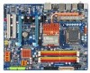
GA-X38-DS4 Motherboard Layout KB_MS RCA_SPDIF USB_1394_1 SYS_FAN1 ATX_12V_2X LGA775 CPU_FAN PCIE_12V ATX USB_1394_2 USB_LAN USB PWR_FAN RTL8111B Intel® X38 AUDIO F_AUDIO PCIE_1 NB_FAN GA-X38-DS4 FDD PCIE_16_1 DDRII1 DDRII2 DDRII3 DDRII4 CODEC CD_IN PCIE_2 PCIE_3 BP_BIOS - Gigabyte GA-X38-DS4 | Manual - Page 8
Bus ATA-133/100/66/ 33 IDE Channel GIGABYTE SATA2 LGA775 Processor CPU CLK+/(400/333/266/200 MHz) Host Interface DDR2 1066/800/667 MHz Intel® X38 Dual Channel Memory MCH CLK (400/333/266/200 MHz) Intel® ICH9R Dual BIOS 6 SATA 3Gb/s 12 USB Ports PCI Bus TSB43AB23 3 IEEE 1394a CODEC - Gigabyte GA-X38-DS4 | Manual - Page 9
manual and follow these procedures: • Prior to installation, do not remove or break motherboard S/N (Serial Number) sticker or warranty when handling electronic components such as a motherboard, CPU or memory. If you do not have an ESD or have a problem related to the use of the product, please - Gigabyte GA-X38-DS4 | Manual - Page 10
in the LGA 775 package (Go to GIGABYTE's website for the latest CPU support list.) Š L2 cache varies with CPU Š 1600/1333/1066/800 MHz FSB Š North Bridge: Intel® X38 Express Chipset Š South Bridge: Intel® ICH9R Š 4 x 1.8V DDR2 DIMM sockets supporting up to 8 GB of system memory (Note 1) Š Dual - Gigabyte GA-X38-DS4 | Manual - Page 11
header Back Panel Š 1 x PS/2 keyboard port Connectors Š 1 x PS/2 mouse port Š 1 x coaxial S/PDIF Out connector Š 1 x optical S/PDIF Out connector Š 8 x USB 2.0/1.1 ports Š 2 x IEEE 1394a ports Š 1 x RJ-45 port Š 6 x audio jacks (Center/Subwoofer Speaker Out/Rear Speaker Out/Side Speaker - Gigabyte GA-X38-DS4 | Manual - Page 12
you install. (Note 3) Available functions in Easytune may differ by motherboard model. (Note 4) The adjustable CPU voltage range depends on the CPU being used. (Note 5) Due to chipset limitation, Intel ICH9R RAID driver does not support Windows 2000 operating system. GA-X38-DS4 Motherboard - 12 - - Gigabyte GA-X38-DS4 | Manual - Page 13
sure that the motherboard supports the CPU. (Go to GIGABYTE's website for the latest CPU support list.) • graphics card, memory, hard drive, etc. 1-3-1 Installing the CPU A. Locate the alignment keys on the motherboard CPU socket and the notches on the CPU. LGA775 CPU Socket Alignment Key LGA 775 - Gigabyte GA-X38-DS4 | Manual - Page 14
B. Follow the steps below to correctly install the CPU into the motherboard CPU socket. Before installing the CPU, make sure to turn off the computer and unplug the properly inserted, replace the load plate and push the CPU socket lever back into its locked position. GA-X38-DS4 Motherboard - 14 - - Gigabyte GA-X38-DS4 | Manual - Page 15
below to correctly install the CPU cooler on the motherboard. (The following procedure uses Intel® boxed cooler as the example cooler.) Step 1: CPU cooler installation manual for instructions on installing the cooler.) Step 5: After the installation, check the back of the motherboard. If the push - Gigabyte GA-X38-DS4 | Manual - Page 16
are installed, a message which says memory is operating in Flex Memory Mode will appear during the POST. Intel® Flex Memory Technology offers greater flexibility to upgrade by allowing different memory sizes to be populated and remain in Dual Channel mode/performance. GA-X38-DS4 Motherboard - 16 - - Gigabyte GA-X38-DS4 | Manual - Page 17
computer and unplug the power cord from the power outlet to prevent damage to the memory module. DDR2 DIMMs are not compatible to DDR DIMMs. Be sure to install DDR2 DIMMs on this motherboard. Notch DDR2 DIMM A DDR2 memory module has a notch, so it can only fit in one direction. Follow the steps - Gigabyte GA-X38-DS4 | Manual - Page 18
on the back of the white-drawable bar to release the card. GA-X38-DS4 Motherboard - 18 - • The motherboard provides a PCIE_12V power connector, which can supply extra power to the onboard PCI Express x16 slots. When you install two graphics cards, connect the power cable from your power supply to - Gigabyte GA-X38-DS4 | Manual - Page 19
secure the SATA bracket to the chassis back panel with a screw. Step 2: Connect the SATA cable from the bracket to the SATA port on your motherboard. Step 3: Step 4: Connect the power Plug one end of the cable from the bracket SATA signal cable into to the power supply. the external SATA - Gigabyte GA-X38-DS4 | Manual - Page 20
to a back panel connector, first remove the cable from your device and then remove it from the motherboard. • When removing the cable, pull it straight out from the connector. Do not rock it side to side to prevent an electrical short inside the cable connector. GA-X38-DS4 Motherboard - 20 - - Gigabyte GA-X38-DS4 | Manual - Page 21
to perform different functions via the audio software. Only microphones still MUST be connected to the default Mic in jack ( ). Refer to the instructions on setting up a 2/4/5.1/ 7.1-channel audio configuration in Chapter 5, "Configuring 2/4/5.1/7.1-Channel Audio." - 21 - Hardware Installation - Gigabyte GA-X38-DS4 | Manual - Page 22
devices. • After installing the device and before turning on the computer, make sure the device cable has been securely attached to the connector on the motherboard. GA-X38-DS4 Motherboard - 22 - - Gigabyte GA-X38-DS4 | Manual - Page 23
can supply enough stable power to all the components on the motherboard. Before connecting the power connector, first make sure the power supply 2x4 12V power connector is recommended by the CPU manufacturer when using an Intel Extreme Edition CPU (130W). • To meet expansion requirements, it is - Gigabyte GA-X38-DS4 | Manual - Page 24
positive connection and requires a +12V voltage. The black connector wire is the ground wire. The motherboard supports CPU fan speed control, which requires the use of a CPU fan with fan speed control design jumper blocks. Do not place a jumper cap on the headers. GA-X38-DS4 Motherboard - 24 - - Gigabyte GA-X38-DS4 | Manual - Page 25
(Power Connector) This power connector can supply extra power to the PCI Express x16 slots on the motherboard. Connect the power supply cable to this connector when using two graphics cards. Failure to do so may lead to an unstable system. 1 PIin No. Definition 1 NC 2 GND 3 GND 4 +12V - Gigabyte GA-X38-DS4 | Manual - Page 26
an even number. • A RAID 5 configuration requires at least three hard drives. (The total number of hard drives does not have to be an even number.) • A RAID 10 configuration requires at least four hard drives and the total number of hard drives must be an even number. GA-X38-DS4 Motherboard - 26 - - Gigabyte GA-X38-DS4 | Manual - Page 27
1 3 MPD- System Status LED S0 On S1 Blinking S3/S4/S5 Off 12) BAT (BATTERY) The battery provides power to keep the values (such as BIOS configurations, date, and time information) in the CMOS when the computer is turned off. Replace the battery when the battery voltage drops to a low level - Gigabyte GA-X38-DS4 | Manual - Page 28
heard if no problem is detected at system startup. If a problem is detected, the BIOS may issue beeps in different patterns to indicate the problem. Refer to Chapter 5, "Troubleshooting," for information about assignments and the pin assignments are matched correctly. GA-X38-DS4 Motherboard - 28 - - Gigabyte GA-X38-DS4 | Manual - Page 29
) The front panel audio header supports Intel High Definition audio (HD) and AC'97 audio. You may connect your chassis front panel audio module to this header. Make sure the wire assignments of the module connector match the pin assignments of the motherboard header. Incorrect connection between the - Gigabyte GA-X38-DS4 | Manual - Page 30
an HDMI display to the graphics card and have digital audio output from the HDMI display at the same time. For information about connecting the S/PDIF digital audio cable, carefully read the manual for your expansion card. Pin No. Definition 1 1 SPDIFO 2 GND GA-X38-DS4 Motherboard - 30 - - Gigabyte GA-X38-DS4 | Manual - Page 31
contact the local dealer. 1 2 9 10 Pin No. 1 2 3 4 5 6 7 8 9 10 Definition TPA+ TPAGND GND TPB+ TPBPower (12V) Power (12V) No Pin GND • Do not plug the USB bracket cable into the IEEE 1394a header. • Prior to installing the IEEE 1394a bracket, be sure to turn off your computer and unplug the - Gigabyte GA-X38-DS4 | Manual - Page 32
VCC3 LAD1 Pin No. 11 12 13 14 15 16 17 18 19 20 Definition LAD0 GND RSVO RSV1 SB3V SERIRQ GND CLKRUN LPCPD RSV2 GA-X38-DS4 Motherboard - 32 - - Gigabyte GA-X38-DS4 | Manual - Page 33
Pin No. 1 2 3 4 5 6 7 8 9 10 Definition NDCD NSIN NSOUT NDTR GND NDSR NRTS NCTS NRI No Pin 23) CI (Chassis Intrusion Header) This motherboard provides a chassis detection feature that detects if the chassis cover has been removed. This function requires a chassis with chassis intrusion detection - Gigabyte GA-X38-DS4 | Manual - Page 34
the jumper. Failure to do so may cause damage to the motherboard. • After system restart, go to BIOS Setup to load factory defaults (select Load Optimized Defaults) or manually configure the BIOS settings (refer to Chapter 2, "BIOS Setup," for BIOS configurations). GA-X38-DS4 Motherboard - 34 - - Gigabyte GA-X38-DS4 | Manual - Page 35
the GIGABYTE Q-Flash or @BIOS utility. • Q-Flash allows the user to quickly and easily upgrade or back up BIOS without entering the operating system. • @BIOS is a Windows-based utility that searches and downloads the latest version of BIOS from the Internet and updates the BIOS. For instructions on - Gigabyte GA-X38-DS4 | Manual - Page 36
, the device boot order will still be based on BIOS Setup settings. You can access Boot Menu again to change the first boot device setting as needed. : Q-Flash Press the key to access the Q-Flash utility directly without having to enter BIOS Setup first. GA-X38-DS4 Motherboard - 36 - - Gigabyte GA-X38-DS4 | Manual - Page 37
Exit Setup Exit Without Saving ESC: Quit F8: Q-Flash KLJI: Select Item F10: Save & Exit Setup F11: Save CMOS to BIOS F12: Load CMOS from BIOS Time, Date, Hard Disk Type... BIOS Setup Program Function Keys Move the selection bar to select an item Execute command or enter the submenu - Gigabyte GA-X38-DS4 | Manual - Page 38
SATA, USB, , memory, BIOS Setup. (Pressing can also carry out this task.) „ Exit Without Saving Abandon all changes and the previous settings remain in effect. Pressing to the confirmation message will exit BIOS Setup. (Pressing can also carry out this task.) GA-X38-DS4 Motherboard - Gigabyte GA-X38-DS4 | Manual - Page 39
[None] [None] [None] [None] [None] Drive A Floppy 3 Mode Support [1.44M, 3.5"] [Disabled] Halt On [All, But Keyboard] Base Memory Extended Memory 640K 510M KLJI: Move Enter: Select F5: Previous Values +/-/PU/PD: Value F10: devices by using one of the three methods below: - 39 - BIOS Setup - Gigabyte GA-X38-DS4 | Manual - Page 40
manually 3 Mode Support Allows you BIOS POST. Base Memory Also called conventional memory. Typically, 640 KB will be reserved for the MS-DOS operating system. Extended Memory The amount of extended memory. Total Memory The total amount of memory installed on the system. GA-X38-DS4 Motherboard - Gigabyte GA-X38-DS4 | Manual - Page 41
Memory Protect (Note) CPU Enhanced Halt (C1E) (Note) CPU Thermal Monitor 2(TM2) (Note) CPU EIST Function (Note) Virtualization Technology USB-FDD, USB-ZIP, USB-CDROM, USB- supports this feature. For more information about Intel CPUs' unique features, please visit Intel's website. - 41 - BIOS Setup - Gigabyte GA-X38-DS4 | Manual - Page 42
Sets PCI Express graphics card on the second PCI Express x16 slot (PCIE_16_2) as the first display. (Note) This item is present only if you install a CPU that supports this feature. For more information about Intel CPUs' unique features, please visit Intel's website. GA-X38-DS4 Motherboard - 42 - Gigabyte GA-X38-DS4 | Manual - Page 43
support Native mode, e.g. Windows XP/2000. USB Controller Enables or disables the integrated USB controller. (Default: Enabled) Disabled will turn off all of the USB functionalities below. USB 2.0 Controller Enables or disables the integrated USB 2.0 controller. (Default: Enabled) - 43 - BIOS - Gigabyte GA-X38-DS4 | Manual - Page 44
to the following information for diagnosing your LAN cable: When No LAN Cable Is Attached... If no LAN cable is attached to the motherboard, the Status fields of all four pairs of wires will show Open and the Length fields show 0.0m, as shown in the figure above. GA-X38-DS4 Motherboard - 44 - - Gigabyte GA-X38-DS4 | Manual - Page 45
10/100/1000 Mbps in Windows mode or when the LAN Boot ROM is activated. When a Cable Problem Occurs... If a cable problem occurs on a specified pair Onboard IDE Controller (GIGABYTE SATA2 Chip) Enables or disables the IDE controller integrated in the GIGABYTE SATA2 chip. (Default - 45 - BIOS Setup - Gigabyte GA-X38-DS4 | Manual - Page 46
Resume by Alarm x Date (of Month) Alarm x Time (hh:mm:ss) Alarm HPET Support (Note) HPET Mode (Note) Power On By Mouse Power On By Keyboard x KB Power a modem that supports wake-up function. (Default: Enabled) (Note) Supported on Windows® Vista® operating system only. GA-X38-DS4 Motherboard - 46 - - Gigabyte GA-X38-DS4 | Manual - Page 47
The system stays off upon the return of the AC power. (Default) Full-On Memory The system is turned on upon the return of the AC power. The system returns to its last known awake state upon the return of the AC power. (Note) Supported on Windows® Vista® operating system only. - 47 - BIOS Setup - Gigabyte GA-X38-DS4 | Manual - Page 48
Help F7: Optimized Defaults BIOS auto-assigns IRQ to the first PCI slot. (Default) Assigns IRQ 3,4,5,7,9,10,11,12,14,15 to the first PCI slot. BIOS auto-assigns IRQ to the second PCI slot. (Default) Assigns IRQ 3,4,5,7,9,10,11,12,14,15 to the second PCI slot. GA-X38-DS4 Motherboard - 48 - - Gigabyte GA-X38-DS4 | Manual - Page 49
the detection status of the chassis intrusion detection device attached to the motherboard CI header. If the system chassis cover is removed, this field threshold for CPU temperature. When CPU temperature exceeds the threshold, BIOS will emit warning sound. Options are: Disabled (default), 60oC - Gigabyte GA-X38-DS4 | Manual - Page 50
configurable only if CPU Smart FAN Control is set to Enabled. Auto Lets BIOS autodetect the type of CPU fan installed and sets the optimal CPU fan is not designed following Intel PWM fan specifications, selecting PWM mode may not effectively reduce the fan speed. GA-X38-DS4 Motherboard - 50 - - Gigabyte GA-X38-DS4 | Manual - Page 51
System Voltage Optimized ******** System Voltage Control [Manual] DDR2 OverVoltage Control [Normal] PCI-E F7: Optimized Defaults • Incorrectly doing overclock/overvoltage may result in damage to CPU, chipset, or memory and reduce the useful life of these supports this feature. - 51 - BIOS Setup - Gigabyte GA-X38-DS4 | Manual - Page 52
first verify the overclocking capability of your CPU. As stability is highly dependent on system components, when system instability occurs after overclocking, lower the overclocking ratio. (Note) This item appears only if you install a CPU that supports this feature. GA-X38-DS4 Motherboard - 52 - Gigabyte GA-X38-DS4 | Manual - Page 53
memory being used; the second is the memory frequency that is automatically adjusted according to the CPU Host Frequency (Mhz) and System Memory Multiplier settings. DRAM Timing Selectable (SPD) Manual (default), 1~31. Command Rate(CMD) Options are: Auto (default), 1T, 2T. - 53 - BIOS Setup - Gigabyte GA-X38-DS4 | Manual - Page 54
reference voltage by 10%. -10% Decreases MCH reference voltage by 10%. DDR Reference Voltage Control Normal BIOS automatically sets the DDR reference voltage. (Default) +10% Increases DDR reference voltage by 10%. -10% Decreases DDR reference voltage by 10%. GA-X38-DS4 Motherboard - 54 - - Gigabyte GA-X38-DS4 | Manual - Page 55
voltage. (Default) +50mV -50mV Increases DDR termination voltage by 50mV. Decreases DDR termination voltage by 50mV. Loadline Calibration Enabled Lets the BIOS fine-tune the CPU Vcore voltage. (Default) Disabled Disables this function. CPU Voltage Control Allows you to set the CPU voltage - Gigabyte GA-X38-DS4 | Manual - Page 56
Press on this item and then press the key to load the optimal BIOS default settings. The BIOS defaults settings helps the system to operate in optimum state. Always load the Optimized defaults after updating the BIOS or after clearing the CMOS values. GA-X38-DS4 Motherboard - 56 - - Gigabyte GA-X38-DS4 | Manual - Page 57
Password Save & Exit Setup Exit Without Saving ESC: Quit F8: Q-Flash KLJI: Select Item F10: Save & Exit Setup F11: Save CMOS to BIOS F12: Load CMOS from BIOS Change/Set/Disable Password Press on this item and type the password with up to 8 characters and then press . You will be - Gigabyte GA-X38-DS4 | Manual - Page 58
Setup F11: Save CMOS to BIOS F12: Load CMOS from BIOS Abandon all Data Press on this item and press the key. This exits the BIOS Setup without saving the changes made in BIOS Setup to the CMOS. Press or to return to the BIOS Setup Main Menu. GA-X38-DS4 Motherboard - 58 - - Gigabyte GA-X38-DS4 | Manual - Page 59
other drivers. • After the drivers are installed, follow the onscreen instructions to restart your system. You can install other applications included in the motherboard driver disk. • For USB 2.0 driver support under the Windows XP operating system, please install the Windows XP Service Pack - Gigabyte GA-X38-DS4 | Manual - Page 60
all the tools and applications that GIGABYTE develops and some free software. You may press the Install button following an item to install it. 3-3 Driver CD Information This page provides information about the drivers, applications and tools in this driver disk. GA-X38-DS4 Motherboard - 60 - - Gigabyte GA-X38-DS4 | Manual - Page 61
3-4 Hardware Information This page provides information about the hardware devices on this motherboard. 3-5 Contact Us Check the contacts information of the GIGABYTE headquarter in Taiwan and the overseas branch offices on the last page of this manual. - 61 - Drivers Installation - Gigabyte GA-X38-DS4 | Manual - Page 62
GA-X38-DS4 Motherboard - 62 - - Gigabyte GA-X38-DS4 | Manual - Page 63
graphics card • Windows® 2000 with SP3 or later; Windows® XP with SP1 or later • Xpress Recovery and Xpress Recovery2 are different utilities. For example, a backup file created with Xpress Recovery cannot be restored using Xpress Recovery2. • USB hard drives are not supported. • Hard drives in RAID - Gigabyte GA-X38-DS4 | Manual - Page 64
Windows XP as the example operating system.) A. Installing Windows XP and Partitioning the Hard Drive 1. Set CD-ROM drive as the first boot device under "Advanced BIOS Features" in the BIOS NTFS) and begin the installation of the operating system (Figure 3). Figure 3 GA-X38-DS4 Motherboard - 64 - - Gigabyte GA-X38-DS4 | Manual - Page 65
4. After the operating system is installed, right-click the My Computer icon on your desktop and select Manage (Figure 4). Go to Computer Management to check disk allocation. Xpress Recovery2 will save the backup file to the unallocated space (black stripe along the top)(Figure 5). Please note that - Gigabyte GA-X38-DS4 | Manual - Page 66
drive contains the Windows operating system. When the Windows operating system is detected, Xpress Recovery2 will begin the backup process (Figure 11). Figure 10 Figure 11 3. When finished, go to Disk Management to check disk allocation. Figure 12 GA-X38-DS4 Motherboard Xpress Recovery2 will - Gigabyte GA-X38-DS4 | Manual - Page 67
D. Using the Restore Function in Xpress Recovery2 Select RESTORE to restore the backup to your hard drive in case the system breaks down. The RESTORE option will not be present if no backup is created before (Figure 13, 14). Figure 13 Figure 14 E. Removing the Backup 1. If you wish to remove the - Gigabyte GA-X38-DS4 | Manual - Page 68
Software, Inc. X38-DS4 F1a . . . . : BIOS Setup : XpressRecovery2 : Boot Menu : Qflash 11/23/2007-X38-ICH9-6A89OG0IC-00 Because BIOS flashing is potentially risky, please do it with caution. Inadequate BIOS flashing may result in system malfunction. GA-X38-DS4 Motherboard - 68 - - Gigabyte GA-X38-DS4 | Manual - Page 69
key to select Update BIOS from Drive and press . • The Save Main BIOS to Drive option allows you to save the current BIOS file. • Q-Flash only supports USB flash drive or hard drives using FAT32/16/12 file system. • If the BIOS update file is saved to a hard drive in RAID/AHCI mode or a hard - Gigabyte GA-X38-DS4 | Manual - Page 70
Setup F11: Save CMOS to BIOS F12: Load CMOS from BIOS Load Optimized Defaults Press to load BIOS defaults Step 6: Select Save & Exit Setup and then press to save settings to CMOS and exit BIOS Setup. The procedure is complete after the system restarts. GA-X38-DS4 Motherboard - 70 - - Gigabyte GA-X38-DS4 | Manual - Page 71
use the C.O.M. (Corporate Online Management) function when using @BIOS. 4. GIGABYTE product warranty does not cover any BIOS damage or system failure resulting from an inadequate BIOS flashing. B. Installing and Using @BIOS: Use the motherboard driver disk included with the motherboard to install - Gigabyte GA-X38-DS4 | Manual - Page 72
BIOS file matches your motherboard model. Updating the BIOS with an incorrect BIOS file could result in an unbootable system. Step 4: As the system boots, press to enter the BIOS Setup program. Select Load Optimized Defaults and press to load BIOS defaults. GA-X38-DS4 Motherboard - Gigabyte GA-X38-DS4 | Manual - Page 73
CPU frequency Shows the supported function(s) Go to GIGABYTE website to update EasyTune 5 Pro Opens EasyTune 5 Pro help file Quits or minimizes the EasyTune 5 Pro interface Performance Enhancement Incorrectly doing overclock/overvoltage may result in damage to CPU, chipset, or memory and reduce the - Gigabyte GA-X38-DS4 | Manual - Page 74
the slider or spin box. Click Apply and then OK to turn on ReadyBoost. • The USB flash drive must have at least 256 MB of space. • The recommended amount of memory to use for ReadyBoost acceleration is one to three times the amount of RAM installed in your computer. GA-X38-DS4 Motherboard - 74 - - Gigabyte GA-X38-DS4 | Manual - Page 75
hard drive. (Note 1) Skip this step if you do not want to create RAID array on the SATA controller. (Note 2) Required when the SATA controller is set to AHCI or RAID mode. (Note 3) Due to chipset limitation, Intel ICH9R RAID driver does not support Windows 2000 operating system. - 75 - Appendix - Gigabyte GA-X38-DS4 | Manual - Page 76
Defaults Step 2: Save changes and exit BIOS Setup. The BIOS Setup menus described in this section may differ from the exact settings for your motherboard. The actual BIOS Setup menu options you will see shall depend on the motherboard you have and the BIOS version. GA-X38-DS4 Motherboard - 76 - - Gigabyte GA-X38-DS4 | Manual - Page 77
C. Configuring a RAID array in RAID BIOS Enter the RAID BIOS setup utility to configure a RAID array. Skip this step and proceed to the installation of Windows operating system for a non-RAID configuration. Step 1: After the POST memory test begins and before the operating system boot begins, look - Gigabyte GA-X38-DS4 | Manual - Page 78
Name : RAID Level : Disks : Strip Size : Capacity : Volume0 RAID0(Stripe) Select Disks 128KB 223.6 GB Create Volume [ HELP ] The following are typical values: RAID0 - 128KB RAID10 - 64KB RAID5 - 64KB [K L ]-Change [TAB]-Next [ESC]-Previous Menu Figure 5 [ENTER]-Select GA-X38-DS4 Motherboard - Gigabyte GA-X38-DS4 | Manual - Page 79
Disk(0) [KL]-Select [ESC]-Exit Figure 7 [ENTER]-Select Menu To exit the ICH9R RAID BIOS utility, press or select Exit in MAIN MENU. Now, you may proceed to create the SATA RAID/AHCI driver diskette and the installation of the SATA RAID/ACHI driver and operating system. - 79 - Appendix - Gigabyte GA-X38-DS4 | Manual - Page 80
. Name Volume0 Intel(R) Matrix Storage Manager option ROM v7.5.0.1017 ICH9R wRAID5 Copyright(C) 2003-07 Intel Corporation. All Rights the disks to non-RAID. WARNING: ALL DISK DATA WILL BE DELETED. [K L ]-Select [ESC]-Previous Menu Figure 8 [DEL]-Delete Volume GA-X38-DS4 Motherboard - 80 - - Gigabyte GA-X38-DS4 | Manual - Page 81
be recognized during the Windows setup process. First of all, copy the driver for the SATA controller from the motherboard driver disk to a floppy disk. See the instructions below about how to copy the driver in MS-DOS mode(Note). Prepare a startup disk that has CD-ROM support and a blank formatted - Gigabyte GA-X38-DS4 | Manual - Page 82
manufacturer, press S. * If you do not have any device support disks from a mass storage device manufacturer, or do not want to specify additional mass storage devices for use with Windows, press ENTER. S=Specify Additional Device ENTER=Continue F3=Exit Figure 2 GA-X38-DS4 Motherboard - 82 - - Gigabyte GA-X38-DS4 | Manual - Page 83
, press to continue the driver installation from the floppy disk. The driver installation will be finished in about one minute. Windows Setup Setup will load support for the following mass storage device(s): Intel(R) ICH8R/ICH9R SATA RAID Controller * To specify additional SCSI adapters - Gigabyte GA-X38-DS4 | Manual - Page 84
prepares Microsoft(R) Windows (R) XP to run on your computer. To set up Windows XP now, press ENTER. To repair a Windows XP installation using Recovery Console, press R. To quit Setup without installing Windows XP, press F3. Enter= Continue R=Repair F3=Exit Figure 5 GA-X38-DS4 Motherboard - 84 - - Gigabyte GA-X38-DS4 | Manual - Page 85
(The procedure below assumes that only one RAID array exists in your system.) Step 1: Restart your system to boot from the Windows Vista setup disk and perform standard OS installation steps. When a screen similar to that below appears, select Load Driver. (Figure 6). Figure 6 Step 2: Specify the - Gigabyte GA-X38-DS4 | Manual - Page 86
8 appears, select Intel(R) ICH8R/ICH9R SATA RAID Controller (Note) and press Next. Figure 8 Step 4: After the driver is loaded, select the RAID/AHCI drive(s) where 8 will be shown as Intel(R) ICH9 SATA AHCI Controller when the SATA controllers are set to AHCI mode. GA-X38-DS4 Motherboard - 86 - - Gigabyte GA-X38-DS4 | Manual - Page 87
in or Line in jack and manually configure the jack for microphone functionality. • If your front panel audio supports Intel HD Audio standard, you can have installed from the motherboard driver disk and your operating system has been updated with the latest Service Pack for Windows. (Note) - Gigabyte GA-X38-DS4 | Manual - Page 88
module, you can only have audio signals present on either the front or the back panel audio connections, but not both at the same time. GA-X38-DS4 Motherboard - 88 - - Gigabyte GA-X38-DS4 | Manual - Page 89
for audio processing. A. Installing the S/PDIF In Cable: Step 1: First, attach the connector at the end of the cable to the SPDIF_IN header on your motherboard. Step 2: Secure the metal bracket to the chassis back panel with a screw. - 89 - Appendix - Gigabyte GA-X38-DS4 | Manual - Page 90
the S/PDIF In/Out Settings dialog box, select an output sampling rate and select (or disable) the output source. Click OK to complete the configuration. GA-X38-DS4 Motherboard - 90 - - Gigabyte GA-X38-DS4 | Manual - Page 91
will transform two-channel stereo source material into multi-channel audio output, creating a virtual surround sound environment(Note). After installing the audio driver, at the center bottom of the Audio Control Panel, you should find the DTS control button as shown below: DTS control button - Gigabyte GA-X38-DS4 | Manual - Page 92
to be output from the S/PDIF OUT. 5-2-4 Configuring Microphone Recording Step 1: After installing the audio driver, the Audio Manager icon will appear in your system tray. Double-click the icon to access the system tray and click it to open the volume control panel. GA-X38-DS4 Motherboard - 92 - - Gigabyte GA-X38-DS4 | Manual - Page 93
Step 4: To hear the sound being recorded during the record- ing process when using the microphone function on or the front panel, do not select the Mute check box under Front Pink In or Front Green In in Master Volume. It is recommended that you set the volume at a middle level. To hear the - Gigabyte GA-X38-DS4 | Manual - Page 94
the Stop button . 5. You may use the Fast Forward button to move to the beginning of a file or the Fast Backward button to the end. GA-X38-DS4 Motherboard - 94 - - Gigabyte GA-X38-DS4 | Manual - Page 95
you identify possible computer problems. (For reference only.) 1 short: System boots successfully 2 short: CMOS setting error 1 long, 1 short: Memory or motherboard error 1 long, 2 short: Monitor or graphics card error 1 long, 3 short: Keyboard error 1 long, 9 short: BIOS ROM error Continuous long - Gigabyte GA-X38-DS4 | Manual - Page 96
insert the memory into the memory socket. The problem is verified and solved. Press to enter BIOS Setup. Select "Load Fail-Safe Defaults" (or "Load Optimized Defaults"). Select "Save & Exit Setup" to save changes and exit BIOS Setup. A (Continued...) GA-X38-DS4 Motherboard - 96 - Gigabyte GA-X38-DS4 | Manual - Page 97
supply, CPU or CPU socket might fail. The problem is verified and solved. No The graphics card, expansion slot, or monitor might fail. The problem is verified and solved. Check if the keyboard is working properly. Yes Press to enter BIOS Setup. Select "Load Fail-Safe Defaults" (or - Gigabyte GA-X38-DS4 | Manual - Page 98
product. Restriction of Hazardous Substances (RoHS) Directive Statement GIGABYTE products have not intended to add and safe from hazardous office, your household waste disposal service or where you purchased the manual and we will be glad to help you with your effort. GA-X38-DS4 Motherboard - 98 - - Gigabyte GA-X38-DS4 | Manual - Page 99
Finally, we suggest that you practice other environmentally friendly actions by understanding and using the energy-saving features of this product (where applicable), recycling the inner and outer packaging (including shipping containers) this product was delivered in, and by disposing of or - Gigabyte GA-X38-DS4 | Manual - Page 100
GA-X38-DS4 Motherboard - 100 - - Gigabyte GA-X38-DS4 | Manual - Page 101
- 101 - Appendix - Gigabyte GA-X38-DS4 | Manual - Page 102
GA-X38-DS4 Motherboard - 102 - - Gigabyte GA-X38-DS4 | Manual - Page 103
Us Taiwan (Headquarters) GIGA-BYTE TECHNOLOGY CO., LTD. Address: No.6, Bau Chiang Road, Hsin-Tien, Taipei 231, Taiwan TEL: +886-2-8912-4888 FAX: +886-2-8912-4003 Tech. and Non-Tech. Support (Sales/Marketing) : http://ggts.gigabyte.com.tw WEB address (English): http://www.gigabyte.com.tw WEB address - Gigabyte GA-X38-DS4 | Manual - Page 104
your language in the language list on the top right corner of the website. GIGABYTE Global Service System To submit a technical or non-technical (Sales/ Marketing) question, please link to : http://ggts.gigabyte.com.tw Then select your language to enter the system. GA-X38-DS4 Motherboard - 104 -
-
 1
1 -
 2
2 -
 3
3 -
 4
4 -
 5
5 -
 6
6 -
 7
7 -
8
-
9
-
10
-
11
-
12
-
13
-
14
-
15
-
16
-
17
-
18
-
19
-
20
-
21
-
22
-
23
-
24
-
25
-
26
-
27
-
28
-
29
-
30
-
31
-
32
-
33
-
34
-
35
-
36
-
37
-
38
-
39
-
40
-
41
-
42
-
43
-
44
-
45
-
46
-
47
-
48
-
49
-
50
-
51
-
52
-
53
-
54
-
55
-
56
-
57
-
58
-
59
-
60
-
61
-
62
-
63
-
64
-
65
-
66
-
67
-
68
-
69
-
70
-
71
-
72
-
73
-
74
-
75
-
76
-
77
-
78
-
79
-
80
-
81
-
82
-
83
-
84
-
85
-
86
-
87
-
88
-
89
-
90
-
91
-
92
-
93
-
94
-
95
-
96
-
97
-
98
-
99
-
100
-
101
-
102
-
103
-
104
 |
 |

GA-X38-DS4
LGA775 socket motherboard for Intel
®
Core
TM
processor family/
Intel
®
Pentium
®
processor family/Intel
®
Celeron
®
processor family
User's Manual
Rev. 1001
12ME-X38DS4-1001R