Gigabyte GA-X38T-DQ6 Manual
Gigabyte GA-X38T-DQ6 Manual
 |
UPC - 818313004239
View all Gigabyte GA-X38T-DQ6 manuals
Add to My Manuals
Save this manual to your list of manuals |
Gigabyte GA-X38T-DQ6 manual content summary:
- Gigabyte GA-X38T-DQ6 | Manual - Page 1
GA-X38T-DQ6 LGA775 socket motherboard for Intel® CoreTM processor family/ Intel® Pentium® processor family/Intel® Celeron® processor family User's Manual Rev. 1002 12ME-X38TDQ6-1002R - Gigabyte GA-X38T-DQ6 | Manual - Page 2
Motherboard GA-X38T-DQ6 Sept. 7, 2007 Motherboard GA-X38T-DQ6 Sept. 7, 2007 - Gigabyte GA-X38T-DQ6 | Manual - Page 3
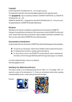
with the product. „ For detailed product information, carefully read the User's Manual. „ For instructions on how to use GIGABYTE's unique features, read or download the information on/from the Support\Motherboard\Technology Guide page on our website. For product-related information, check on our - Gigabyte GA-X38T-DQ6 | Manual - Page 4
...6 OptionalItems ...6 GA-X38T-DQ6 Motherboard Layout 7 Block Memory 17 1-4-1 Dual Channel Memory Configuration 17 1-4-2 Installing a Memory 18 1-5 Installing an Expansion Card 19 1-6 Installing the SATA Bracket 20 1-7 Back Panel Connectors 21 1-8 Internal Connectors 23 Chapter 2 BIOS - Gigabyte GA-X38T-DQ6 | Manual - Page 5
Updating the BIOS with the Q-Flash Utility 70 4-2-2 Updating the BIOS with the @BIOS Utility 73 4-3 EasyTune 5 Pro 75 4-4 Windows Vista ReadyBoost 76 Chapter 5 Appendix ...77 5-1 Configuring SATA Hard Drive(s 77 5-1-1 Configuring Intel® ICH9R SATA Controllers 77 5-1-2 Configuring GIGABYTE - Gigabyte GA-X38T-DQ6 | Manual - Page 6
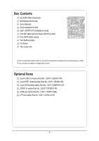
Box Contents GA-X38T-DQ6 motherboard Motherboard driver disk User's Manual Quick Installation Guide Intel® LGA775 CPU Installation Guide One IDE cable and one floppy disk drive cable Four SATA 3Gb/s cables Two SATA brackets I/O Shield Two screw nuts The box contents above are - Gigabyte GA-X38T-DQ6 | Manual - Page 7
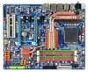
GA-X38T-DQ6 Motherboard Layout KB_MS SYS_FAN1 RCA_SPDIF ATX_12V_2X USB_1394_1 LGA775 CPU_FAN PCIE_12V ATX USB_1394_2 USB_LAN PWR_FAN USB_LAN2 RTL8111B AUDIO NB_FAN Intel® X38 F_AUDIO RTL8111B CODEC CD_IN PCIE_1 PCIE_16_1 GA-X38T-DQ6 PCIE_2 BP_BIOS PCIE_3 BAT SPDIF_O MAIN BIOS - Gigabyte GA-X38T-DQ6 | Manual - Page 8
Bus 2 SATA 3Gb/s ATA-133/100/66/ 33 IDE Channel GIGABYTE SATA2 PCI Bus TSB43AB23 3 IEEE 1394a Host Interface DDR3 1600/1333/1066/800 MHz Intel® X38 Dual Channel Memory MCH CLK (400/333/266/200 MHz) Intel® ICH9R CODEC Dual BIOS 6 SATA 3Gb/s 12 USB Ports IT8718 Floppy LPT Port COM Port - Gigabyte GA-X38T-DQ6 | Manual - Page 9
's manual and follow these procedures: • Prior to installation, do not remove or break motherboard S/N wrist strap when handling electronic components such as a motherboard, CPU or memory. If you do not have an ESD wrist steps or have a problem related to the use of the product, please consult - Gigabyte GA-X38T-DQ6 | Manual - Page 10
SATA RAID 0, RAID 1, and JBOD Š iTE IT8718 chip: - 1 x floppy disk drive connector supporting up to 1 floppy disk drive Š T.I. TSB43AB23 chip Š Up to 3 IEEE 1394a ports (2 on the back panel, 1 via the IEEE 1394a bracket connected to the internal IEEE 1394a header) GA-X38T-DQ6 Motherboard - 10 - - Gigabyte GA-X38T-DQ6 | Manual - Page 11
, 4 via the USB brackets connected to the internal USB headers) Internal Connectors Š 1 x 24-pin ATX main power connector Š 1 x 8-pin ATX 12V power connector Š 1 x 4-pin PCIe 12V power connector Š 1 x floppy disk drive connector Š 1 x IDE connector Š 8 x SATA 3Gb/s connectors Š 1 x CPU fan - Gigabyte GA-X38T-DQ6 | Manual - Page 12
than 4 GB. (Note 2) Available functions in Easytune may differ by motherboard model. (Note 3) The adjustable CPU voltage range depends on the CPU being used. (Note 4) Due to chipset limitation, Intel ICH9R RAID driver does not support Windows 2000 operating system. GA-X38T-DQ6 Motherboard - 12 - - Gigabyte GA-X38T-DQ6 | Manual - Page 13
the CPU: • Make sure that the motherboard supports the CPU. (Go to GIGABYTE's website for the latest CPU support list.) • Always turn off the computer memory, hard drive, etc. 1-3-1 Installing the CPU A. Locate the alignment keys on the motherboard CPU socket and the notches on the CPU. LGA775 CPU - Gigabyte GA-X38T-DQ6 | Manual - Page 14
English B. Follow the steps below to correctly install the CPU into the motherboard CPU socket. Before installing the CPU, make sure to turn off the computer and unplug inserted, replace the load plate and push the CPU socket lever back into its locked position. GA-X38T-DQ6 Motherboard - 14 - - Gigabyte GA-X38T-DQ6 | Manual - Page 15
below to correctly install the CPU cooler on the motherboard. (The following procedure uses Intel® boxed cooler as the example cooler.) Step 1: CPU cooler installation manual for instructions on installing the cooler.) Step 5: After the installation, check the back of the motherboard. If the push - Gigabyte GA-X38T-DQ6 | Manual - Page 16
Back of the Motherboard To install a non-Intel CPU cooler that requires extra mounting holes, follow the steps below to remove the Crazy Cool heatsink from the back of the motherboard. 1. Use extreme received may vary in appearance from the ones illustrated above. GA-X38T-DQ6 Motherboard - 16 - - Gigabyte GA-X38T-DQ6 | Manual - Page 17
following guidelines before you begin to install the memory: • Make sure that the motherboard supports the memory. It is recommended that memory of the same capacity, brand, speed, and chips be used. (Go to GIGABYTE's website for the latest memory support list.) • Always turn off the computer and - Gigabyte GA-X38T-DQ6 | Manual - Page 18
in the picture on the left, place your fingers on the top edge of the memory, push down on the memory and insert it vertically into the memory socket. Step 2: The clips at both ends of the socket will snap into place when the memory module is securely inserted. GA-X38T-DQ6 Motherboard - 18 - - Gigabyte GA-X38T-DQ6 | Manual - Page 19
an expansion card: • Make sure the motherboard supports the expansion card. Carefully read the manual that came with your expansion card. • Always If necessary, go to BIOS Setup to make any required BIOS changes for your expansion card(s). 7. Install the driver provided with the expansion card - Gigabyte GA-X38T-DQ6 | Manual - Page 20
panel with a screw. Step 2: Connect the SATA cable from the bracket to the SATA port on your motherboard. Step 3: Step 4: Connect the power Plug one end of the cable from the bracket SATA signal cable make sure to turn off the power of the external enclosure. GA-X38T-DQ6 Motherboard - 20 - - Gigabyte GA-X38T-DQ6 | Manual - Page 21
Use this port for an IEEE 1394a device. USB Port The USB port supports the USB 2.0/1.1 specification. Use this port for USB devices such as an , first remove the cable from your device and then remove it from the motherboard. • When removing the cable, pull it straight out from the connector. - Gigabyte GA-X38T-DQ6 | Manual - Page 22
to perform different functions via the audio software. Only microphones still MUST be connected to the default Mic in jack ( ). Refer to the instructions on setting up a 2/4/5.1/ 7.1-channel audio configuration in Chapter 5, "Configuring 2/4/5.1/7.1-Channel Audio." GA-X38T-DQ6 Motherboard - 22 - - Gigabyte GA-X38T-DQ6 | Manual - Page 23
7 2 6 8 14 23 25 9 15 11 17 12 21 16 22 24 20 4 18 19 13 9 10 1) ATX_12V_2X 2) ATX (Power Connector) 3) CPU_FAN 4) SYS_FAN1 / SYS_FAN2 5) PWR_FAN 6) NB_FAN 7) PCIE_12V 8) FDD 9) SATAII0 / 1 / 2 / 3 / securely attached to the connector on the motherboard. - 23 - Hardware Installation - Gigabyte GA-X38T-DQ6 | Manual - Page 24
connector is recommended by the CPU manufacturer when using an Intel Extreme Edition CPU (130W). • To meet expansion 2x4 pin 12V) 6 +12V (Only for 2x4 pin 12V) 7 +12V 8 +12V 12 24 1 13 ATX GA-X38T-DQ6 Motherboard ATX : Pin No. 1 2 3 4 5 6 7 8 9 10 11 12 Definition 3.3V 3.3V GND - Gigabyte GA-X38T-DQ6 | Manual - Page 25
connector wires. A red power connector wire indicates a positive connection and requires a +12V voltage. The black connector wire is the ground wire. The motherboard supports CPU fan speed control, which requires the use of a CPU fan with fan speed control design. For optimum heat dissipation, it is - Gigabyte GA-X38T-DQ6 | Manual - Page 26
drives supported are: 360 KB, 720 KB, 1.2 MB, 1.44 MB, and 2.88 MB. Before connecting a floppy disk drive, be sure to locate pin 1 of the connector and the floppy disk drive cable. The pin 1 of the cable is typically designated by a stripe of different color. 34 33 2 1 GA-X38T-DQ6 Motherboard - Gigabyte GA-X38T-DQ6 | Manual - Page 27
are compatible with SATA 1.5Gb/s standard. Each SATA connector supports a single SATA device. The GIGABYTE SATA2 controller supports RAID 0 and RAID 1. Refer to Chapter 5, "Configuring SATA Hard Drive(s)," for instructions on configuring a RAID array. 7 1 GSATAIIA Pin No. 1 2 Definition GND - Gigabyte GA-X38T-DQ6 | Manual - Page 28
IDE Connector) The IDE connector supports up to two IDE devices (For information about configuring master/slave settings for the IDE devices, read the instructions from the device manufacturers.) 1 2 39 40 12) PWR_LED (System Power On S1 Blinking S3/S4/S5 Off GA-X38T-DQ6 Motherboard - 28 - - Gigabyte GA-X38T-DQ6 | Manual - Page 29
a beep code. One single short beep will be heard if no problem is detected at system startup. If a problem is detected, the BIOS may issue beeps in different patterns to indicate the problem. Refer to Chapter 5, "Troubleshooting," for information about beep codes. • HD (IDE Hard Drive Activity LED - Gigabyte GA-X38T-DQ6 | Manual - Page 30
10 NC • The front panel audio header supports HD audio by default. If your chassis provides an AC'97 front panel audio module, refer to the instructions on how to activate AC'97 functioninality via header. 1 Pin No. Definition 1 CD-L 2 GND 3 GND 4 CD-R GA-X38T-DQ6 Motherboard - 30 - - Gigabyte GA-X38T-DQ6 | Manual - Page 31
This header supports digital S/PDIF out and connects a S/PDIF digital audio cable (provided by expansion cards) for digital audio output from your motherboard to certain PDIF digital audio cable, carefully read the manual for your expansion card. 1 Pin No. Definition 1 SPDIFO 2 GND - 31 - Gigabyte GA-X38T-DQ6 | Manual - Page 32
USB bracket, be sure to turn off your computer and unplug the power cord from the power outlet to prevent damage to the USB bracket. GA-X38T-DQ6 Motherboard - 32 - - Gigabyte GA-X38T-DQ6 | Manual - Page 33
English 20) COM (Serial Port Header, White) The COM header can provide one serial port via an optional COM port cable. For purchasing the optional COM port cable, please contact the local dealer. 2 10 1 9 Pin No. 1 2 3 4 5 6 7 8 9 10 Definition NDCDNSIN NSOUT NDTRGND NDSRNRTSNCTSNRINo Pin 21 - Gigabyte GA-X38T-DQ6 | Manual - Page 34
the jumper. Failure to do so may cause damage to the motherboard. • After system restart, go to BIOS Setup to load factory defaults (select Load Optimized Defaults) or manually configure the BIOS settings (refer to Chapter 2, "BIOS Setup," for BIOS configurations). GA-X38T-DQ6 Motherboard - 34 - - Gigabyte GA-X38T-DQ6 | Manual - Page 35
English 24) CI (Chassis Intrusion Header) This motherboard provides a chassis detection feature that detects if the chassis GND 25) BAT (Battery) The battery provides power to keep the values (such as BIOS configurations, date, and time information) in the CMOS when the computer is turned off. - Gigabyte GA-X38T-DQ6 | Manual - Page 36
English GA-X38T-DQ6 Motherboard - 36 - - Gigabyte GA-X38T-DQ6 | Manual - Page 37
the GIGABYTE Q-Flash or @BIOS utility. • Q-Flash allows the user to quickly and easily upgrade or back up BIOS without entering the operating system. • @BIOS is a Windows-based utility that searches and downloads the latest version of BIOS from the Internet and updates the BIOS. For instructions on - Gigabyte GA-X38T-DQ6 | Manual - Page 38
An Energy Star Ally Copyright (C) 1984-2007, Award Software, Inc. Motherboard Model BIOS Version Intel X38 BIOS for X38T-DQ6 F1a . . . . : BIOS Setup : XpressRecovery2 : Boot Menu : Qflash 08/23/2007-X38-ICH9-6A79OG0RC-00 Function Keys Function Keys: : POST Screen Press - Gigabyte GA-X38T-DQ6 | Manual - Page 39
Exit Setup Exit Without Saving ESC: Quit F8: Q-Flash KLJI: Select Item F10: Save & Exit Setup F11: Save CMOS to BIOS F12: Load CMOS from BIOS Time, Date, Hard Disk Type... BIOS Setup Program Function Keys Move the selection bar to select an item Execute command or enter the submenu - Gigabyte GA-X38T-DQ6 | Manual - Page 40
CPU, memory, etc. BIOS Setup. (Pressing can also carry out this task.) „ Exit Without Saving Abandon all changes and the previous settings remain in effect. Pressing to the confirmation message will exit BIOS Setup. (Pressing can also carry out this task.) GA-X38T-DQ6 Motherboard - Gigabyte GA-X38T-DQ6 | Manual - Page 41
[None] [None] [None] [None] [None] [None] Drive A Floppy 3 Mode Support [1.44M, 3.5"] [Disabled] Halt On [All, But Keyboard] KLJI: Move Enter: Select F5: : General Help F7: Optimized Defaults Base Memory Extended Memory Total Memory CMOS Setup Utility-Copyright (C) 1984-2007 Award BIOS Setup - Gigabyte GA-X38T-DQ6 | Manual - Page 42
manually 3 Mode Support Allows you BIOS POST. Base Memory Also called conventional memory. Typically, 640 KB will be reserved for the MS-DOS operating system. Extended Memory The amount of extended memory. Total Memory The total amount of memory installed on the system. GA-X38T-DQ6 Motherboard - Gigabyte GA-X38T-DQ6 | Manual - Page 43
and to issue warnings when a third party hardware monitor utility is installed. (Default: Disabled) (Note) This item is present only if you install a CPU that supports this feature. For more information about Intel CPUs' unique features, please visit Intel's website. - 43 - BIOS Setup - Gigabyte GA-X38T-DQ6 | Manual - Page 44
PEG2 Sets PCI Express graphics card on the second PCIe x16 slot (PCIE_16_2) as the first display. (Note) This item is present only if you install a CPU that supports this feature. For more information about Intel CPUs' unique features, please visit Intel's website. GA-X38T-DQ6 Motherboard - 44 - - Gigabyte GA-X38T-DQ6 | Manual - Page 45
USB Controller USB 2.0 Controller USB Keyboard Support USB Mouse Support Legacy USB storage detect Azalia Codec Onboard Mode (Intel ICH9R Southbridge) Enables or disables RAID for the SATA controllers integrated in the Intel ICH9R that allows the storage driver to enable advanced Serial ATA features such - Gigabyte GA-X38T-DQ6 | Manual - Page 46
SATA Port0-3 Native Mode (Intel ICH9R Southbridge) Specifies the option to Disabled if you wish to install operating systems that do not support Native mode, e.g. Windows 9X/ME. (Default) Enabled Allows the SATA controllers to operate in set this item to Disabled. GA-X38T-DQ6 Motherboard - 46 - - Gigabyte GA-X38T-DQ6 | Manual - Page 47
LAN Cable Is Attached... If no LAN cable is attached to the motherboard, the Status fields of all four pairs of wires will show Open of 10/100/1000Mbps in Windows mode or when the LAN Boot ROM is activated. When a Cable Problem Occurs... If a cable problem occurs on a specified pair - BIOS Setup - Gigabyte GA-X38T-DQ6 | Manual - Page 48
GIGABYTE SATA 2 chip. (Default: Enabled) Onboard SATA/IDE Ctrl Mode (GIGABYTE SATA2 Chip) Enables or disables RAID for the SATA controller integrated in the GIGABYTE an interface specification that allows the storage driver to enable advanced Serial ATA features such GA-X38T-DQ6 Motherboard - 48 - - Gigabyte GA-X38T-DQ6 | Manual - Page 49
, you need an ATX power supply providing at least 1A on the 5VSB lead. (Default: Enabled) Power On by Ring Allows the system to be awakened from an ACPI sleep state by a wake-up signal from a modem that supports wake-up function. (Default: Enabled) (Note) Supported on Windows® Vista® operating - Gigabyte GA-X38T-DQ6 | Manual - Page 50
off upon the return of the AC power. (Default ) Full-On The system is turned on upon the return of the AC power. Memory The system returns to its last known awake state upon the return of the AC power. (Note) Supported on Windows® Vista® operating system only. GA-X38T-DQ6 Motherboard - 50 - - Gigabyte GA-X38T-DQ6 | Manual - Page 51
IRQ Assignment Auto 3,4,5,7,9,10,11,12,14,15 +/-/PU/PD: Value F10: Save F6: Fail-Safe Defaults ESC: Exit F1: General Help F7: Optimized Defaults BIOS auto-assigns IRQ to the first PCI slot. (Default) Assigns IRQ 3,4,5,7,9,10,11,12,14,15 to the first PCI slot - Gigabyte GA-X38T-DQ6 | Manual - Page 52
Warning Temperature Sets the warning threshold for CPU temperature. When CPU temperature exceeds the threshold, BIOS will emit warning sound. Options are: Disabled (default), 60oC/140oF, 70oC/158oF, 80oC/ or fan connection when this occurs. (Default: Disabled) GA-X38T-DQ6 Motherboard - 52 - - Gigabyte GA-X38T-DQ6 | Manual - Page 53
is configurable only if CPU Smart FAN Control is set to Enabled. Auto Lets BIOS autodetect the type of CPU fan installed and sets the optimal CPU fan control mode fan that is not designed following Intel PWM fan specifications, selecting PWM mode may not effectively reduce the fan speed. - 53 - Gigabyte GA-X38T-DQ6 | Manual - Page 54
Normal CPU Vcore 4 6 1 ******** Auto Auto Auto [Manual] [Normal] [Normal] [Normal] [Normal] [Normal] : Optimized Defaults • Incorrectly doing overclock/overvoltage may result in damage to CPU, chipset, or memory and reduce the useful life of supports this feature. GA-X38T-DQ6 Motherboard - 54 - - Gigabyte GA-X38T-DQ6 | Manual - Page 55
of the graphics chip and memory. Auto allows the BIOS to automatically set the R.G.B. Note: If your system fails to boot after overclocking, please wait for 20 seconds to allow for automated manually set the PCIe clock frequency. The adjustable range is from 90 MHz supports this feature. - 55 - BIOS Setup - Gigabyte GA-X38T-DQ6 | Manual - Page 56
overclock the DDR2 memory, select Option 1 or Option 2 to help make your system more stable. Option 1 Memory Timing Configuration 1. (Default) Option 2 Memory Timing Configuration 2. DRAM Timing Selectable (SPD) Manual Options are: Auto (default), 1~31. GA-X38T-DQ6 Motherboard - 56 - - Gigabyte GA-X38T-DQ6 | Manual - Page 57
whether to manually set the system voltages. Auto lets BIOS automatically set the system voltages as required. Manual allows all voltage control items below to be configurable. (Default: Manual) DDR3 OverVoltage Control Allows you to to set memory voltage. Normal Supplies the memory voltage as - Gigabyte GA-X38T-DQ6 | Manual - Page 58
Press on this item and then press the key to load the optimal BIOS default settings. The BIOS defaults settings helps the system to operate in optimum state. Always load the Optimized defaults after updating the BIOS or after clearing the CMOS values. GA-X38T-DQ6 Motherboard - 58 - - Gigabyte GA-X38T-DQ6 | Manual - Page 59
Password Save & Exit Setup Exit Without Saving ESC: Quit F8: Q-Flash KLJI: Select Item F10: Save & Exit Setup F11: Save CMOS to BIOS F12: Load CMOS from BIOS Change/Set/Disable Password Press on this item and type the password with up to 8 characters and then press . You will be - Gigabyte GA-X38T-DQ6 | Manual - Page 60
Setup F11: Save CMOS to BIOS F12: Load CMOS from BIOS Abandon all Data Press on this item and press the key. This exits the BIOS Setup without saving the changes made in BIOS Setup to the CMOS. Press or to return to the BIOS Setup Main Menu. GA-X38T-DQ6 Motherboard - 60 - - Gigabyte GA-X38T-DQ6 | Manual - Page 61
other drivers. • After the drivers are installed, follow the onscreen instructions to restart your system. You can install other applications included in the motherboard driver disk. • For USB 2.0 driver support under the Windows XP operating system, please install the Windows XP Service Pack - Gigabyte GA-X38T-DQ6 | Manual - Page 62
all the tools and applications that GIGABYTE develops and some free software. You may press the Install button following an item to install it. 3-3 Driver CD Information This page provides information about the drivers, applications and tools in this driver disk. GA-X38T-DQ6 Motherboard - 62 - - Gigabyte GA-X38T-DQ6 | Manual - Page 63
English 3-4 Hardware Information This page provides information about the hardware devices on this motherboard. 3-5 Contact Us Check the contacts information of the GIGABYTE headquarter in Taiwan and the overseas branch offices on the last page of this manual. - 63 - Drivers Installation - Gigabyte GA-X38T-DQ6 | Manual - Page 64
English GA-X38T-DQ6 Motherboard - 64 - - Gigabyte GA-X38T-DQ6 | Manual - Page 65
data and perform restoration of it. Supporting NTFS, FAT32, and FAT16 file systems system soon after the operating system and drivers are installed. • The amount of data and Intel® x86 platform • At least 64 MB of system memory • VESA compatible graphics card • Windows® 2000 with SP3 or later; Windows - Gigabyte GA-X38T-DQ6 | Manual - Page 66
Windows XP as the example operating system.) A. Installing Windows XP and Partitioning the Hard Drive 1. Set CD-ROM drive as the first boot device under "Advanced BIOS Features" in the BIOS NTFS) and begin the installation of the operating system (Figure 3). Figure 3 GA-X38T-DQ6 Motherboard - 66 - - Gigabyte GA-X38T-DQ6 | Manual - Page 67
English 4. After the operating system is installed, right-click the My Computer icon on your desktop and select Manage (Figure 4). Go to Computer Management to check disk allocation. Xpress Recovery2 will save the backup file to the unallocated space (black stripe along the top)(Figure 5). Please - Gigabyte GA-X38T-DQ6 | Manual - Page 68
drive contains the Windows operating system. When the Windows operating system is detected, Xpress Recovery2 will begin the backup process (Figure 11). Figure 10 Figure 11 3. When finished, go to Disk Management to check disk allocation. Figure 12 GA-X38T-DQ6 Motherboard Xpress Recovery2 will - Gigabyte GA-X38T-DQ6 | Manual - Page 69
English D. Using the Restore Function in Xpress Recovery2 Select RESTORE to restore the backup to your hard drive in case the system breaks down. The RESTORE option will not be present if no backup is created before (Figure 13, 14). Figure 13 Figure 14 E. Removing the Backup 1. If you wish to - Gigabyte GA-X38T-DQ6 | Manual - Page 70
. Intel X38 BIOS for X38T-DQ6 F1a . . . . : BIOS Setup : XpressRecovery2 : Boot Menu : Qflash 08/23/2007-X38-ICH9-6A79OG0RC-00 Because BIOS flashing is potentially risky, please do it with caution. Inadequate BIOS flashing may result in system malfunction. GA-X38T-DQ6 Motherboard - Gigabyte GA-X38T-DQ6 | Manual - Page 71
Update BIOS from Drive and press . • The Save Main BIOS to Drive option allows you to save the current BIOS file. • Q-Flash only supports USB BIOS update file and press . Make sure the BIOS update file matches your motherboard model. Step 2: The process of the system reading the BIOS - Gigabyte GA-X38T-DQ6 | Manual - Page 72
Setup F11: Save CMOS to BIOS F12: Load CMOS from BIOS Load Optimized Defaults Press to load BIOS defaults Step 6: Select Save & Exit Setup and then press to save settings to CMOS and exit BIOS Setup. The procedure is complete after the system restarts. GA-X38T-DQ6 Motherboard - 72 - - Gigabyte GA-X38T-DQ6 | Manual - Page 73
Using @BIOS: Use the motherboard driver disk included with the motherboard to install @BIOS. • Installing the @BIOS utility. • Accessing the @BIOS utility. Select @BIOS and click Install. Click Start>All Programs>GIGABYTE> @BIOS>@BIOS C. Options and Instructions: 1. Save the Current BIOS File - Gigabyte GA-X38T-DQ6 | Manual - Page 74
BIOS file matches your motherboard model. Updating the BIOS with an incorrect BIOS file could result in an unbootable system. Step 4: As the system boots, press to enter the BIOS Setup program. Select Load Optimized Defaults and press to load BIOS defaults. GA-X38T-DQ6 Motherboard - Gigabyte GA-X38T-DQ6 | Manual - Page 75
BIOS Setup program. EasyTune 5 Pro provides the following functions (Note 1): overclocking/overvoltage, C.I.A./M.I.B. (Note 2), smart fan control, and hardware monitoring and warning. (For instructions on using EasyTune5 Pro, read or download the information on/from the Support\Motherboard\Utility - Gigabyte GA-X38T-DQ6 | Manual - Page 76
. Click Apply and then OK to turn on ReadyBoost. • The USB flash drive must have at least 256 MB of space. • The recommended amount of memory to use for ReadyBoost acceleration is one to three times the amount of RAM installed in your computer. GA-X38T-DQ6 Motherboard - 76 - - Gigabyte GA-X38T-DQ6 | Manual - Page 77
empty formatted floppy disk. • Windows Vista/XP/2000 (Note 3) setup disk. • Motherboard driver disk. 5-1-1 Configuring Intel® ICH9R SATA Controllers A. Installing example, on this motherboard, the SATAII0, SATAII1, SATAII2, SATAII3, SATAII4 and SATAII5 ports are supported by ICH9R Southbridge.) - Gigabyte GA-X38T-DQ6 | Manual - Page 78
USB Keyboard Support USB Mouse Support Legacy BIOS Setup. The BIOS Setup menus described in this section may differ from the exact settings for your motherboard. The actual BIOS Setup menu options you will see shall depend on the motherboard you have and the BIOS version. GA-X38T-DQ6 Motherboard - Gigabyte GA-X38T-DQ6 | Manual - Page 79
BIOS Enter the RAID BIOS setup utility to configure a RAID array. Skip this step and proceed to the installation of Windows operating system for a non-RAID configuration. Step 1: After the POST memory test Intel(R) Matrix Storage Manager option ROM v7.5.0.1014 ICH9R wRAID5 Copyright(C) 2003-07 Intel - Gigabyte GA-X38T-DQ6 | Manual - Page 80
select a RAID level (Figure 4). There are four RAID levels supported: RAID 0, RAID 1, RAID 10 and RAID 5 (the , press . Intel(R) Matrix Storage Manager option ROM v7.5.0.1014 ICH9R wRAID5 Copyright(C) 2003-07 Intel Corporation. All Rights 5 [ENTER]-Select GA-X38T-DQ6 Motherboard - 80 - - Gigabyte GA-X38T-DQ6 | Manual - Page 81
6). Intel(R) Matrix Storage Manager option ROM v7.5.0.1014 ICH9R wRAID5 Copyright(C) 2003-07 Intel Corporation 7) Intel(R) Matrix Storage Manager option ROM v7.5.0.1014 ICH9R wRAID5 Copyright(C) 2003-07 Intel Corporation. the ICH9R RAID BIOS utility, press or select Exit in MAIN MENU. - Gigabyte GA-X38T-DQ6 | Manual - Page 82
confirm or to abort. Name Volume0 Intel(R) Matrix Storage Manager option ROM v7.5.0.1014 ICH9R wRAID5 Copyright(C) 2003-07 Intel Corporation. All Rights Reversed. [ DELETE VOLUME WILL BE DELETED. [K L ]-Select [ESC]-Previous Menu Figure 8 [DEL]-Delete Volume GA-X38T-DQ6 Motherboard - 82 - - Gigabyte GA-X38T-DQ6 | Manual - Page 83
port. (For example, on this motherboard, the GSATAIIA and GSATAIIB ports are supported by GIGABYTE SATA2.) Then connect the power connector from 1: Turn on your computer and press to enter BIOS Setup during the POST. In BIOS Setup, go to Integrated Peripherals, ensure that Onboard SATA/IDE - Gigabyte GA-X38T-DQ6 | Manual - Page 84
Disk Drive List ] [IJTAB]-Switch Window [KL]-Select ITEM [ENTER]-Action Figure 3 [ESC]-Exit (Note) In the main screen, you can select a hard drive in the Hard Disk Drive List block and press to see detailed information about the selected hard drive. GA-X38T-DQ6 Motherboard - 84 - - Gigabyte GA-X38T-DQ6 | Manual - Page 85
characters in length for the created RAID drive to be identified by system BIOS or OS. [IJ]-Move Cursor [DEL,BS]-Delete Character [ENTER]-Next (Figure 5). Then press to move onto the next step. GIGABYTE Technology Corp. PCIE-to-SATAII/IDE RAID Controller BIOSv1.06.59 [ Create New RAID ] - Gigabyte GA-X38T-DQ6 | Manual - Page 86
DATA ON THE SELECTED HARD DISK WILL BE LOST WHEN EXIT WITH SAVING [KL]-Switch Unit [DEL,BS]-Delete Number Figure 7 [ENTER]-Next [ESC]-Abort GA-X38T-DQ6 Motherboard - 86 - - Gigabyte GA-X38T-DQ6 | Manual - Page 87
bar to the RAID Disk Drive List block. Select the array and press . A small window displaying the array information will appear in the center of the screen (Figure 9). GIGABYTE Technology Corp. PCIE-to-SATAII/IDE RAID Controller BIOSv1.06.59 [ Main Menu ] [ Hard Disk Drive List ] Create - Gigabyte GA-X38T-DQ6 | Manual - Page 88
BIOS utility, then press (Figure 10). GIGABYTE Technology Corp. PCIE- Window [KL]-Select ITEM [ENTER]-Action Figure 10 [ESC]-Exit Now, you may proceed to create the SATA RAID/AHCI driver diskette and the installation of the SATA RAID/AHCI driver GA-X38T-DQ6 Motherboard - 88 - [ESC]-Abort - Gigabyte GA-X38T-DQ6 | Manual - Page 89
Manager 32 bit for Windows 32-bit operating system or 8) Intel Matrix Storage Manager 64 bit for Windows 64-bit. • For GIGABYTE SATA2 SATA controller, select E) GIGABYTE SATA-RAID Driver 32Bit for Windows 32-bit operating system or F) GIGABYTE SATA-RAID Driver 64Bit for Windows 64-bit. Your system - Gigabyte GA-X38T-DQ6 | Manual - Page 90
manufacturer, press S. * If you do not have any device support disks from a mass storage device manufacturer, or do not want to specify additional mass storage devices for use with Windows, press ENTER. S=Specify Additional Device ENTER=Continue F3=Exit Figure 2 GA-X38T-DQ6 Motherboard - 90 - - Gigabyte GA-X38T-DQ6 | Manual - Page 91
the motherboard driver disk. When the screen as shown below appears, press to continue the driver installation from the floppy disk. The driver installation will be finished in about one minute. Windows Setup Setup will load support for the following mass storage device(s): Intel(R) ICH8R - Gigabyte GA-X38T-DQ6 | Manual - Page 92
manufacturer, press S. * If you do not have any device support disks from a mass storage device manufacturer, or do not want to specify additional mass storage devices for use with Windows, press ENTER. S=Specify Additional Device ENTER=Continue F3=Exit Figure 6 GA-X38T-DQ6 Motherboard - 92 - - Gigabyte GA-X38T-DQ6 | Manual - Page 93
Step 4: After the SATA RAID/AHCI driver installation is completed, you can proceed with the Windows XP installation. WindowsXP Professional Setup Welcome to Setup. This port of the Setup program prepares Microsoft(R) Windows (R) XP to run on your computer. To set up Windows XP now, press ENTER. To - Gigabyte GA-X38T-DQ6 | Manual - Page 94
from the Windows Vista setup disk and perform standard OS installation steps. When a screen similar to that below appears, select Load Driver. (Figure 8). Figure 8 Step 2: Specify the location where the driver is saved, such as your floppy disk (Figure 9). Figure 9 GA-X38T-DQ6 Motherboard - 94 - Gigabyte GA-X38T-DQ6 | Manual - Page 95
English Step 3: When a screen as shown in Figure 10 appears, select Intel(R) ICH8R/ICH9R SATA RAID Controller (Note) and press Next. Figure 10 Step 4: After the driver is loaded, select the RAID/AHCI drive(s) where you want to install the operating system and then press Next to continue the OS - Gigabyte GA-X38T-DQ6 | Manual - Page 96
steps. When a screen similar to that below appears (RAID/AHCI hard drive(s) will not be detected at this stage), select Load Driver. (Figure 12). Figure 12 Step 2: Specify the location where the driver is saved, such as your floppy disk (Figure 13). Figure 13 GA-X38T-DQ6 Motherboard - 96 - - Gigabyte GA-X38T-DQ6 | Manual - Page 97
English Step 3: When a screen as shown in Figure 14 appears, select GIGABYTE GBB36X Controller and press Next. Figure 14 Step 4: After the driver is loaded, select the RAID/AHCI drive(s) where you want to install the operating system and then press Next to continue the OS installation (Figure - Gigabyte GA-X38T-DQ6 | Manual - Page 98
or Line in jack and manually configure the jack for microphone functionality. • If your front panel audio supports Intel HD Audio standard, you the motherboard driver disk and your operating system has been updated with the latest Service Pack for Windows. speaker out. GA-X38T-DQ6 Motherboard - 98 - - Gigabyte GA-X38T-DQ6 | Manual - Page 99
English Step 2: Click the Audio I/O tab. In the speaker list on the left, select 2CH Speaker, 4CH Speaker, 6CH Speaker, or 8CH Speaker according to the type of speaker configuration you wish to set up. Step 3: Everytime you connect an audio device to an audio jack, the Connected device box appears. - Gigabyte GA-X38T-DQ6 | Manual - Page 100
for audio processing. A. Installing the S/PDIF In Cable: Step 1: First, attach the connector at the end of the cable to the SPDIF_IN header on your motherboard. Step 2: Secure the metal bracket to the chassis back panel with a screw. GA-X38T-DQ6 Motherboard - 100 - - Gigabyte GA-X38T-DQ6 | Manual - Page 101
English S/PDIF Out: The S/PDIF out jacks can transmit audio signals to an external decoder for decoding to get the best audio quality. B. Conneting a S/PDIF out Cable Connect a S/PDIF coaxial cable or a S/PDIF optical cable (either one) to an external decoder for transmitting the S/PDIF digital - Gigabyte GA-X38T-DQ6 | Manual - Page 102
-channel audio output, creating a virtual surround sound environment(Note). After installing the audio driver, at the center bottom of the Audio Control Panel, you should find the DTS control working, and you will not hear sound from analog speaker or headphone. GA-X38T-DQ6 Motherboard - 102 - - Gigabyte GA-X38T-DQ6 | Manual - Page 103
that are not digitally processed by DTS encoding to be output from the S/PDIF OUT. 5-2-4 Configuring Microphone Recording Step 1: After installing the audio driver, the Audio Manager icon will appear in your system tray. Double-click the icon to access the Audio Control Panel. Step 2: Connect your - Gigabyte GA-X38T-DQ6 | Manual - Page 104
, or you will not hear any sound when playing back the recording you just made. Select Realtek HD Audio Input in the Mixer device list GA-X38T-DQ6 Motherboard Recording Control - 104 - - Gigabyte GA-X38T-DQ6 | Manual - Page 105
Step 6: To raise the recording and playing sound for the microphone, go to Options in Master Volume and select Advanced Controls. Click the Advanced button under a volume control option (e.g. Front Green In, Front Pink In). In the Other Controls field, select the 1 Microphone Boost check box. Step - Gigabyte GA-X38T-DQ6 | Manual - Page 106
A. Enable Teaming functionality with Windows XP: Select Realtek Ethernet Teaming Utility and click Install. Step 1: Install the driver CD for the motherboard, and then choose Software , please click the item you created, and then click the Remove button. GA-X38T-DQ6 Motherboard - 106 - - Gigabyte GA-X38T-DQ6 | Manual - Page 107
English B. Enable Teaming functionality with Windows Vista: Select Realtek Ethernet Teaming Utility and click Install. Step 1: Install the driver CD for the motherboard, and then choose Software Applications; Click Install under Realtek Ethernet Teaming Utility for installation, and reboot after - Gigabyte GA-X38T-DQ6 | Manual - Page 108
setting error 1 long, 1 short: Memory or motherboard error 1 long, 2 short: Monitor or graphics card error 1 long, 3 short: Keyboard error 1 long, 9 short: BIOS ROM error Continuous long beeps: Graphics card not inserted properly Continuous short beeps: Power error GA-X38T-DQ6 Motherboard - 108 - - Gigabyte GA-X38T-DQ6 | Manual - Page 109
Procedure If you encounter any troubles during system startup, follow the troubleshooting procedure below to solve the problem. START Turn off the power. Remove all peripherals, connecting cables, and power cord etc. Make sure the motherboard does not short-circuit with the chassis or - Gigabyte GA-X38T-DQ6 | Manual - Page 110
exit BIOS Setup. No The keyboard or mouse might fail. The problem is problem, contact the place of purchase or local dealer for help. Or go to the Support\Technical Service Zone page to submit your question. Our customer service staff will reply you as soon as possible. GA-X38T-DQ6 Motherboard - Gigabyte GA-X38T-DQ6 | Manual - Page 111
GIGABYTE. Our Commitment to Preserving the Environment In addition to high-efficiency performance, all GIGABYTE motherboards local government office, your household waste disposal service or where you purchased the product for user's manual and we will be glad to help you with your effort. - - Gigabyte GA-X38T-DQ6 | Manual - Page 112
disposed of properly. China Restriction of Hazardous Substances Table The following table is supplied in compliance with China's Restriction of Hazardous Substances (China RoHS) requirements: GA-X38T-DQ6 Motherboard - 112 - - Gigabyte GA-X38T-DQ6 | Manual - Page 113
- 113 - Appendix English - Gigabyte GA-X38T-DQ6 | Manual - Page 114
English GA-X38T-DQ6 Motherboard - 114 - - Gigabyte GA-X38T-DQ6 | Manual - Page 115
(Soporte de habla hispano) FAX: +1-626-854-9339 Correo: [email protected] Tech. Support: http://rma.gigabyte-usa.com Web address: http://www.gigabyte.com.mx Singapore GIGA-BYTE SINGAPORE PTE. LTD. WEB address : http://www.gigabyte.sg Thailand WEB address : http://th.giga-byte.com Vietnam WEB - Gigabyte GA-X38T-DQ6 | Manual - Page 116
your language in the language list on the top right corner of the website. GIGABYTE Global Service System To submit a technical or non-technical (Sales/ Marketing) question, please link to : http://ggts.gigabyte.com.tw Then select your language to enter the system. GA-X38T-DQ6 Motherboard - 116 -
-
 1
1 -
 2
2 -
 3
3 -
 4
4 -
 5
5 -
 6
6 -
 7
7 -
8
-
9
-
10
-
11
-
12
-
13
-
14
-
15
-
16
-
17
-
18
-
19
-
20
-
21
-
22
-
23
-
24
-
25
-
26
-
27
-
28
-
29
-
30
-
31
-
32
-
33
-
34
-
35
-
36
-
37
-
38
-
39
-
40
-
41
-
42
-
43
-
44
-
45
-
46
-
47
-
48
-
49
-
50
-
51
-
52
-
53
-
54
-
55
-
56
-
57
-
58
-
59
-
60
-
61
-
62
-
63
-
64
-
65
-
66
-
67
-
68
-
69
-
70
-
71
-
72
-
73
-
74
-
75
-
76
-
77
-
78
-
79
-
80
-
81
-
82
-
83
-
84
-
85
-
86
-
87
-
88
-
89
-
90
-
91
-
92
-
93
-
94
-
95
-
96
-
97
-
98
-
99
-
100
-
101
-
102
-
103
-
104
-
105
-
106
-
107
-
108
-
109
-
110
-
111
-
112
-
113
-
114
-
115
-
116
 |
 |

GA-X38T-DQ6
LGA775 socket motherboard for Intel
®
Core
TM
processor family/
Intel
®
Pentium
®
processor family/Intel
®
Celeron
®
processor family
User's Manual
Rev. 100
2
12ME-X38TDQ6-100
2
R