Gigabyte GA-X58A-UD7 Manual
Gigabyte GA-X58A-UD7 Manual
 |
UPC - 818313009494
View all Gigabyte GA-X58A-UD7 manuals
Add to My Manuals
Save this manual to your list of manuals |
Gigabyte GA-X58A-UD7 manual content summary:
- Gigabyte GA-X58A-UD7 | Manual - Page 1
GA-X58A-UD7 LGA1366 socket motherboard for Intel® Core™ i7 processor family User's Manual Rev. 1002 12ME-X58AUD7-1002R - Gigabyte GA-X58A-UD7 | Manual - Page 2
Motherboard GA-X58A-UD7 Nov. 13, 2009 Motherboard GA-X58A-UD7 Nov. 13, 2009 - Gigabyte GA-X58A-UD7 | Manual - Page 3
set-up of the product, read the Quick Installation Guide included with the product. For detailed product information, carefully read the User's Manual. For instructions on how to use GIGABYTE's unique features, read or download the information on/from the Support&Downloads\Motherboard\Technology - Gigabyte GA-X58A-UD7 | Manual - Page 4
Items...6 GA-X58A-UD7 Motherboard Layout 7 Block Diagram...8 Chapter 1 Hardware Installation 9 1-1 Installation Precautions 9 1-2 Product Specifications 10 1-3 Installing the CPU and CPU Cooler 13 1-3-1 Installing the CPU 13 1-3-2 Installing the CPU Cooler 15 1-4 Installing the Hybrid - Gigabyte GA-X58A-UD7 | Manual - Page 5
3 Drivers Installation 67 3-1 Installing Chipset Drivers 67 3-2 Application Software 68 3-3 Technical Manuals 68 3-4 Contact...69 3-5 System...69 3-6 Download Center 70 3-7 New Utilities...70 Chapter 4 Unique Features 71 4-1 Xpress Recovery2 71 4-2 BIOS Update Utilities 74 4-2-1 Updating the - Gigabyte GA-X58A-UD7 | Manual - Page 6
Box Contents GA-X58A-UD7 motherboard Motherboard driver disk User's Manual Quick Installation Guide One IDE cable Four SATA 3Gb/s cables One SATA 2-port IEEE 1394a bracket (Part No. 12CF1-1IE008-0*R) 2-port SATA power cable (Part No. 12CF1-2SERPW-0*R) S/PDIF In cable (Part No. 12CR1-1SPDIN-0*R) - 6 - - Gigabyte GA-X58A-UD7 | Manual - Page 7
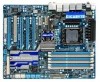
GA-X58A-UD7 Motherboard Layout FREQ. LED PHASE LED KB_MS R_SPDIF ATX_12V_2X CMOS_SW USB_1394_ESATA_2 USB_1394_ESATA_1 CPU_FAN CPU Voltage L1/2/3 CPU TEMP L1/2 LGA1366 RST_SW PW_SW GA-X58A-UD7 PWR_FAN USB_LAN ATX USB30_LAN JMicron JMB362 DDR Voltage LED DDR PHASE LED F_AUDIO NB TEMP - Gigabyte GA-X58A-UD7 | Manual - Page 8
Block Diagram 2 PCI Express x16 4 PCI Express x8 PCIe CLK (100 MHz) or LGA1366 CPU CPU CLK+/- (133 MHz) DDR3 2200/1333/1066/800 MHz Dual/3 Channel Memory x16 x8 PCI Express Bus Switch LAN1 LAN2 QPI Interface Intel® X58 IOH CLK (133 MHz) PCI Express Bus x1 x1 PCIe CLK (100 MHz) PCIe CLK - Gigabyte GA-X58A-UD7 | Manual - Page 9
It is best to wear an electrostatic discharge (ESD) wrist strap when handling electronic com- ponents such as a motherboard, CPU or memory. If you do not have an ESD wrist strap, keep your hands dry and first touch a metal object to eliminate static electricity. • Prior to installing the motherboard - Gigabyte GA-X58A-UD7 | Manual - Page 10
series processor in the LGA1366 package (Go to GIGABYTE's website for the latest CPU support list.) L3 cache varies with CPU QPI 4.8GT/s, 6.4GT/s Chipset North Bridge: Intel® X58 Express Chipset South Bridge: Intel® ICH10R Memory 6 x 1.5V DDR3 DIMM sockets supporting up to 24 GB - Gigabyte GA-X58A-UD7 | Manual - Page 11
3Gb/s devices - Support for SATA RAID 0, RAID 1, and JBOD iTE IT8720 chip: - 1 x floppy disk drive connector supporting up to 1 SATA 3Gb/s connectors w 2 x SATA 6Gb/s connectors w 1 x CPU fan header w 3 x system fan headers w 1 x power fan header w 1 x North Bridge fan header w 1 x front - Gigabyte GA-X58A-UD7 | Manual - Page 12
CPU fan fail warning CPU/System fan speed control (Note 4) 2 x 16 Mbit flash Use of licensed AWARD BIOS Support for DualBIOS™ PnP 1.0a, DMI 2.0, SM BIOS 2.4, ACPI 1.0b Support for @BIOS Support for Q-Flash Support for Xpress BIOS Rescue Support for Download Center Support for Xpress Install Support - Gigabyte GA-X58A-UD7 | Manual - Page 13
and CPU Cooler Read the following guidelines before you begin to install the CPU: • Make sure that the motherboard supports the CPU. (Go to GIGABYTE's website for the latest CPU support list.) • Always turn off the computer and unplug the power cord from the power outlet before installing the CPU to - Gigabyte GA-X58A-UD7 | Manual - Page 14
the steps below to correctly install the CPU into the motherboard CPU socket. Before installing the CPU, make sure to turn off the computer and unplug the power cord from the power outlet to prevent damage to the CPU. CPU Socket Lever Step 1: Completely raise the CPU socket lever. Step 2: Lift the - Gigabyte GA-X58A-UD7 | Manual - Page 15
your CPU cooler installation manual for instructions on installing the cooler.) Step 5: After the installation, check the back of the motherboard. If the push pin is inserted as the picture above shows, the installation is complete. Step 6: Finally, attach the power connector of the CPU cooler to - Gigabyte GA-X58A-UD7 | Manual - Page 16
Pipe module: If you want to connect the front audio module from your chassis to the F_AUDIO connector on the motherboard, be sure to connect it before installing the Hybrid Silent-Pipe module to avoid interference. Tools needed: 1. A Philip's screwdriver 2. Thermal grease 3. Screws included with the - Gigabyte GA-X58A-UD7 | Manual - Page 17
you begin to install the memory: • Make sure that the motherboard supports the memory. It is recommended that memory of the same capacity, brand, speed, and chips be used. (Go to GIGABYTE's website for the latest memory support list.) • Always turn off the computer and unplug the power cord from the - Gigabyte GA-X58A-UD7 | Manual - Page 18
to turn off the computer and unplug the power cord from the power outlet to prevent damage to the memory module. DDR3 and DDR2 DIMMs are not compatible to each other or DDR DIMMs. Be sure to install DDR3 DIMMs on this motherboard. Notch DDR3 DIMM A DDR3 memory module has a notch, so it can only fit - Gigabyte GA-X58A-UD7 | Manual - Page 19
guidelines before you begin to install an expansion card: • Make sure the motherboard supports the expansion card. Carefully read the manual that came with your expansion card. • Always turn off the computer and unplug the power cord from the power outlet before installing an expansion card to - Gigabyte GA-X58A-UD7 | Manual - Page 20
.) - One/two CrossFire (Note)/SLI bridge connectors - A power supply with sufficient power is recommended (Refer to the manual of your graphics cards for the power requirement) B. Connecting the Graphics Cards Step 1: Observe the steps in "1-5 Installing an Expansion Card" and install two/three - Gigabyte GA-X58A-UD7 | Manual - Page 21
below to install the SATA bracket: Step 1: Locate one free PCI slot and secure the SATA bracket to the chassis back panel with a screw. Step 2: Connect the SATA cable from the bracket to the SATA port on your motherboard. Step 3: Connect the power cable from the bracket to the power supply. Step - Gigabyte GA-X58A-UD7 | Manual - Page 22
, USB flash drive and etc. eSATA/USB Combo Connector This connector supports SATA 3Gb/s and USB 2.0/1.1 specification. Use the port to connect an first remove the cable from your device and then remove it from the motherboard. • When removing the cable, pull it straight out from the connector - Gigabyte GA-X58A-UD7 | Manual - Page 23
USB 3.0/2.0 Port The USB 3.0 port supports the USB 3.0 specification and is compatible to the USB 2.0/1.1 specification. Use this connected to the default Mic in jack ( ). Refer to the instructions on setting up a 2/4/5.1/7.1-channel audio configuration in Chapter 5, "Configuring 2/4/5.1/7.1-Channel - Gigabyte GA-X58A-UD7 | Manual - Page 24
This motherboard contains 4 sets of overvoltage LEDs which indicate the overvoltage level of the CPU, memory, North Bridge, and South Bridge. CPU (High, red) Overclock LEDs The onboard CPU overclock LEDs indicate on which level the CPU is overclocked. The higher the overclock level, the more the - Gigabyte GA-X58A-UD7 | Manual - Page 25
Switches This motherboard has 2 quick buttons: power button and reset button. The power button and reset button allow users to quickly turn on/off or reset the computer in an open-case environment when they want to change hardware components or conduct hardware testing. PW_SW: Power switch RST_SW - Gigabyte GA-X58A-UD7 | Manual - Page 26
DDR PHASE LED The number of lighted LEDs indicates the memory loading. The higher the memory loading, the more the number of lighted LEDs. Hardware Installation - 26 - - Gigabyte GA-X58A-UD7 | Manual - Page 27
sure to turn off the devices and your computer. Unplug the power cord from the power outlet to prevent damage to the devices. • After installing the device and before turning on the computer, make sure the device cable has been securely attached to the connector on the motherboard. - 27 - Hardware - Gigabyte GA-X58A-UD7 | Manual - Page 28
are compatible with power supplies with 2x2 12V and 2x10 power connectors. When using a power supply providing a 2x4 12V and a 2x12 power connector, remove the protective covers from the 12V power connector and the main power connector on the motherboard. Do not insert the power supply cables - Gigabyte GA-X58A-UD7 | Manual - Page 29
fan headers, and a 3-pin power fan header (PWR_FAN). Most fan headers possess a foolproof insertion design. When connecting a fan cable, be sure to connect it in the correct orientation (the black connector wire is the ground wire). The motherboard supports CPU fan speed control, which requires the - Gigabyte GA-X58A-UD7 | Manual - Page 30
, remember to set the jumpers and the cabling according to the role of the IDE devices (for example, master or slave). (For information about configuring master/slave settings for the IDE devices, read the instructions from the device manufacturers.) 39 1 40 2 Hardware Installation - 30 - - Gigabyte GA-X58A-UD7 | Manual - Page 31
to SATA 3Gb/s standard and are compatible with SATA 1.5Gb/s standard. Each SATA connector supports a single SATA device. The GIGABYTE SATA2 controller supports RAID 0, RAID 1, and JBOD. Refer to Chapter 5, "Configuring SATA Hard Drive(s)," for instructions on configuring a RAID array. GSATA2_9 - Gigabyte GA-X58A-UD7 | Manual - Page 32
compatible with SATA 3Gb/s and SATA 1.5Gb/s standards. Each SATA connector supports a single SATA device. The Marvell 9128 supports RAID 0 and RAID 1. Refer to Chapter 5, "Configuring SATA Hard Drive(s)," for instructions battery provides power to keep the values (such as BIOS configurations, date - Gigabyte GA-X58A-UD7 | Manual - Page 33
Message/Power/ Power Sleep powered off (S5). • PW (Power Switch, Red): Connects to the power problem is detected at system startup. If a problem is detected, the BIOS may issue beeps in different patterns to indicate the problem. Refer to Chapter 5, "Troubleshooting power switch, reset switch, power - Gigabyte GA-X58A-UD7 | Manual - Page 34
The front panel audio header supports Intel High Definition audio (HD) and AC'97 audio. You may connect your chassis front panel audio module to this header. Make sure the wire assignments of the module connector match the pin assignments of the motherboard header. Incorrect connection between the - Gigabyte GA-X58A-UD7 | Manual - Page 35
Power 1 2 SPDIFI 3 GND 17) SPDIF_O (S/PDIF Out Header) This header supports digital S/PDIF Out and connects a S/PDIF digital audio cable (provided by expansion cards) for digital audio output from your motherboard read the manual for your expansion card. 1 Pin No. Definition 1 SPDIFO 2 GND - Gigabyte GA-X58A-UD7 | Manual - Page 36
NC • Do not plug the IEEE 1394 bracket (2x5-pin) cable into the USB header. • Prior to installing the USB bracket, be sure to turn off your computer and unplug the power cord from the power outlet to prevent damage to the USB bracket. 19) F_1394 (IEEE 1394a Header) The header conforms to - Gigabyte GA-X58A-UD7 | Manual - Page 37
the GIGABYTE Q-Flash or @BIOS utility. • Q-Flash allows the user to quickly and easily upgrade or back up BIOS without entering the operating system. • @BIOS is a Windows-based utility that searches and downloads the latest version of BIOS from the Internet and updates the BIOS. For instructions on - Gigabyte GA-X58A-UD7 | Manual - Page 38
v6.00PG, An Energy Star Ally Copyright (C) 1984-2009, Award Software, Inc. Motherboard Model BIOS Version X58A-UD7 D33 . . . . : BIOS Setup : XpressRecovery2 : Boot Menu : Qflash 10/27/2009-X58-ICH10-7A89QC0IC-00 Function Keys Function Keys Function Keys: : POST SCREEN - Gigabyte GA-X58A-UD7 | Manual - Page 39
Power Management Setup PC Health Status Load Fail-Safe Defaults Load Optimized Defaults Set Supervisor Password Set User Password Save & Exit Setup Exit Without Saving ESC: Quit F8: Q-Flash Select Item F10: Save & Exit Setup Change CPU's Clock & Voltage F11: Save CMOS to BIOS F12 - Gigabyte GA-X58A-UD7 | Manual - Page 40
before, without the hassles of reconfiguring the BIOS settings. First select the profile you wish to load, then press to complete. MB Intelligent Tweaker(M.I.T.) Use this menu to configure the clock, frequency and voltages of your CPU, memory, etc. Standard CMOS Features Use this - Gigabyte GA-X58A-UD7 | Manual - Page 41
: Optimized Defaults Whether the system will work stably with the overclock/overvoltage settings you made is dependent on your overall system configurations. Incorrectly doing overclock/overvoltage may result in damage to CPU, chipset, or memory and reduce the useful life of these components. This - Gigabyte GA-X58A-UD7 | Manual - Page 42
Tech. Allows you to determine whether to enable the Intel CPU Turbo Boost technology. (Default: Enabled) (Note) This item is present only if you install a CPU that supports this feature. For more information about Intel CPUs' unique features, please visit Intel's website. BIOS Setup - 42 - - Gigabyte GA-X58A-UD7 | Manual - Page 43
technology when using an Intel CPU that supports this function. This feature only works for operating systems that support multi-processor mode. (Default: Enabled) CPU Enhanced Halt (C1E) (Note) Enables or disables Intel CPU Enhanced Halt (C1E) function, a CPU power-saving function in system - Gigabyte GA-X58A-UD7 | Manual - Page 44
you to set the QPI Support CPU Clock Skew IOH Clock Skew [Disabled] 133 [Auto] [ 800mV] [ 900mV] [ 0ps] [ 0ps] Item Help Menu Level Move Enter: Select F5: Previous Values +/-/PU/PD: Value F10: Save F6: Fail-Safe Defaults ESC: Exit F1: General Help F7: Optimized Defaults BIOS - Gigabyte GA-X58A-UD7 | Manual - Page 45
overclocking, please wait for 20 seconds to allow for automated system reboot, or clear the CMOS values to reset the board to default values. (Default: Disabled) BCLK Frequency(Mhz) Allows you to manually set the CPU 900mV (default), 1000mV. CPU Clock Skew Allows you to set the CPU clock prior to the - Gigabyte GA-X58A-UD7 | Manual - Page 46
(X.M.P.) is set to Profile1 or Profile2, this item will display the value based on the SPD data on the XMP memory. Profile QPI Voltage The value displayed here is dependent on the CPU being used. (Note) This item appears only if you install a memory module that supports this feature. BIOS Setup - Gigabyte GA-X58A-UD7 | Manual - Page 47
are: Auto (default), 1~4. >>>>> Channel A/B/C Timing Settings CMOS Setup Utility-Copyright (C) 1984-2009 Award Software Channel A Timing Settings >>>>> Channel A Standard Timing Control x CAS Latency Options are: Auto (default), 1~31. tWR Options are: Auto (default), 1~15. - 47 - BIOS Setup - Gigabyte GA-X58A-UD7 | Manual - Page 48
1~255. >>>>> Channel A/B/C Turnaround Settings CMOS Setup Utility-Copyright (C) 1984-2009 Award Software Channel A Turnaround Settings >>>>> Channel A Reads Followed by 1~8. On The Same Rank Options are: Auto (default), 1~2. BIOS Setup - 48 - ESC: Exit F1: General Help F7: Optimized Defaults - Gigabyte GA-X58A-UD7 | Manual - Page 49
Control Voltage Types Normal Current >>> CPU Load-Line Calibration [Standard] CPU Vcore 1.22500V [Auto] QPI/Vtt Voltage 1.150V [Auto] CPU PLL 1.800V [Auto] >>> MCH F6: Fail-Safe Defaults ESC: Exit F1: General Help F7: Optimized Defaults - 49 - BIOS Setup - Gigabyte GA-X58A-UD7 | Manual - Page 50
-Line Calibration may keep the CPU voltage more constant under light and heavy CPU load. Standard Disables Load-Line Calibration and sets VDroop following Intel specifications. (De- fault) -B Address VRef. The default is Auto. Ch-C Address VRef. The default is Auto. BIOS Setup - 50 - - Gigabyte GA-X58A-UD7 | Manual - Page 51
Memory Extended Memory Total Memory 640K 1022M 1024M Move Enter: Select F5: Previous Values +/-/PU/PD: Value F10: Save F6: Fail-Safe Defaults ESC: Exit F1: General Help F7: Optimized Defaults Date (mm:dd:yy) Sets set the date. Time (hh:mm:ss) Sets set the - Gigabyte GA-X58A-UD7 | Manual - Page 52
only and are determined by the BIOS POST. Base Memory Also called conventional memory. Typically, 640 KB will be reserved for the MS-DOS operating system. Extended Memory The amount of extended memory. Total Memory The total amount of memory installed on the system. BIOS Setup - 52 - - Gigabyte GA-X58A-UD7 | Manual - Page 53
hard drive and to issue warnings when a third party hardware monitor utility is installed. (Default: Disabled) (Note) This item is present only if you install a CPU that supports this feature. For more information about Intel CPUs' unique features, please visit Intel's website. - 53 - BIOS Setup - Gigabyte GA-X58A-UD7 | Manual - Page 54
as the first display. PCIE x8-2 Sets the PCI Express graphics card on the PCIEX8_2 slot as the first display. (Note) This item is present only if you install a CPU that supports this feature. For more information about Intel CPUs' unique features, please visit Intel's website. BIOS Setup - 54 - - Gigabyte GA-X58A-UD7 | Manual - Page 55
disables the X.H.D function for the SATA controllers integrated in the Intel ICH10R Chipset. When set to Enabled, the ICH SATA Control Mode item below will be set to RAID(XHD) automatically. For details on using the GIGABYTE X.H.D utility, refer to Chaper 4, "eXtreme Hard Drive (X.H.D)." (Default - Gigabyte GA-X58A-UD7 | Manual - Page 56
driver to enable advanced Serial ATA features such as Native Command Queuing and hot plug. SATA Port0-3 Native Mode (Intel function. (Default: Enabled) If you wish to install a 3rd party add-in network card instead of using the onboard LAN, set this item to Disabled. Green LAN When the - Gigabyte GA-X58A-UD7 | Manual - Page 57
Cable Is Attached... If no LAN cable is attached to the motherboard, the Status fields of all four pairs of wires will show 10/100/1000 Mbps in Windows mode or when the LAN Boot ROM is activated. When a Cable Problem Occurs... If a cable problem occurs on a specified pair ) - 57 - BIOS Setup - Gigabyte GA-X58A-UD7 | Manual - Page 58
allows the storage driver to enable the storage driver to enable instructions on configuring a RAID array. GSATA 8_9/IDE Controller (GIGABYTE GIGABYTE SATA2 chip. (Default: Enabled) GSATA 8_9/IDE Ctrl Mode (GIGABYTE integrated in the GIGABYTE SATA2 chip or allows the storage driver to enable advanced - Gigabyte GA-X58A-UD7 | Manual - Page 59
supply providing at least 1A on the +5VSB lead. (Default: Enabled) Power On by Ring Allows the system to be awakened from an ACPI sleep state by a wake-up signal from a modem that supports wake-up function. (Default: Enabled) (Note) Supported on Windows Vista operating system only. - 59 - BIOS - Gigabyte GA-X58A-UD7 | Manual - Page 60
-bit mode when you install 64-bit Windows Vista. This item is configurable only if the HPET Support is set to Enabled. (Default: 32-bit mode) Power On By Mouse Allows the system to be turned on by a PS/2 mouse wake-up event. Note: To use this function, you need an ATX power supply providing at least - Gigabyte GA-X58A-UD7 | Manual - Page 61
. Current CPU/MCH Temperature Displays current CPU/North Bridge temperature. Current CPU/SYSTEM/POWER FAN Speed (RPM) Displays current CPU/system/power fan speed. CPU Warning Temperature Sets the warning threshold for CPU temperature. When CPU temperature exceeds the threshold, BIOS will emit - Gigabyte GA-X58A-UD7 | Manual - Page 62
is configurable only if CPU Smart FAN Control is set to Enabled. Auto Lets the BIOS automatically detect the type of CPU fan installed and sets the optimal CPU fan control mode. (Default) Voltage Sets Voltage mode for a 3-pin CPU fan. PWM Sets PWM mode for a 4-pin CPU fan. Note: The Voltage - Gigabyte GA-X58A-UD7 | Manual - Page 63
Defaults Advanced BIOS Features Set Supervisor Password Integrated Peripherals Set User Password Power Management Setup BIOS default settings. In case system instability occurs, you may try to load Fail-Safe defaults, which are the safest and most stable BIOS settings for the motherboard - Gigabyte GA-X58A-UD7 | Manual - Page 64
MB Intelligent Tweaker(M.I.T.) Standard CMOS Features Advanced BIOS Features Integrated Peripherals Power Management SetupEnter Password: PC Health Status Load Fail-Safe Defaults Load Optimized Defaults Set Supervisor Password Set User Password Save & Exit Setup Exit Without Saving ESC - Gigabyte GA-X58A-UD7 | Manual - Page 65
Tweaker(M.I.T.) Load Fail-Safe Defaults Standard CMOS Features Advanced BIOS Features Load Optimized Defaults Save to CMOS and EXITSe(Yt S/Nup)?erYvisor Password Integrated Peripherals Set User Password Power Management Setup Save & Exit Setup PC Health Status Exit Without - Gigabyte GA-X58A-UD7 | Manual - Page 66
BIOS Setup - 66 - - Gigabyte GA-X58A-UD7 | Manual - Page 67
to install other drivers. • After the drivers are installed, follow the on-screen instructions to restart your system. You can install other applications included in the motherboard driver disk. • For USB 2.0 driver support under the Windows XP operating system, please install the Windows XP Service - Gigabyte GA-X58A-UD7 | Manual - Page 68
that GIGABYTE develops and some free software. You can click the Install button on the right of an item to install it. 3-3 Technical Manuals This page provides GIGABYTE's application guides, content descriptions for this driver disk, and the motherboard manuals. Drivers Installation - 68 - Gigabyte GA-X58A-UD7 | Manual - Page 69
3-4 Contact For the detailed contact information of the GIGABYTE Taiwan headquarter or worldwide branch offices, click the URL on this page to link to the GIGABYTE website. 3-5 System This page provides the basic system information. - 69 - Drivers Installation - Gigabyte GA-X58A-UD7 | Manual - Page 70
To update the BIOS, drivers, or applications, click the Download Center button to link to the GIGABYTE website. The latest version of the BIOS, drivers, or applications will be displayed. 3-7 New Utilities This page provides a quick link to GIGABYTE's lately developed utilities for users to install - Gigabyte GA-X58A-UD7 | Manual - Page 71
and drivers are installed. • The amount of data and hard drive access speed may affect the speed at which the data is backed up/ restored. • It takes longer to back up a hard drive than to restore it. System Requirements: • At least 512 MB of system memory • VESA compatible graphics card • Windows - Gigabyte GA-X58A-UD7 | Manual - Page 72
the amount of data) and begin the installation of the operating system. Step 4: After the operating system is installed, right-click the Computer icon on the backup file. B. Accessing Xpress Recovery2 1. Boot from the motherboard driver disk to access Xpress Recovery2 for the first time. When you - Gigabyte GA-X58A-UD7 | Manual - Page 73
D. Using the Restore Function in Xpress Recovery2 Select RESTORE to restore the backup to your hard drive in case the system breaks down. The RESTORE option will not be present if no backup is created before. E. Removing the Backup Step 1: If you wish to - Gigabyte GA-X58A-UD7 | Manual - Page 74
system BIOS while in the Windows environment. @BIOS will download the latest BIOS file from the nearest @BIOS server 4-2-1 Updating the BIOS with the Q-Flash Utility A. Before You Begin 1. From GIGABYTE's website, download the latest compressed BIOS update file that matches your motherboard model - Gigabyte GA-X58A-UD7 | Manual - Page 75
Drive Enter : Run hi:Move ESC:Reset F10:Power Off Total size : 0 Free size : 0 3. Select the BIOS update file and press . Make sure the BIOS update file matches your motherboard model. Step 2: The process of the system reading the BIOS file from the floppy disk is displayed on the - Gigabyte GA-X58A-UD7 | Manual - Page 76
BIOS Setup. Select Load Optimized Defaults and press to load BIOS defaults. System will re-detect all peripheral devices after a BIOS update, so we recommend that you reload BIOS Advanced BIOS Features Set Supervisor Password Integrated Peripherals Set User Password Power Management - Gigabyte GA-X58A-UD7 | Manual - Page 77
. If the BIOS update file for your motherboard is not present on the @BIOS server site, please manually download the BIOS update file from GIGABYTE's website and follow the instructions in "Update the BIOS without Using the Internet Update Function" below. 2. Update the BIOS without Using the - Gigabyte GA-X58A-UD7 | Manual - Page 78
in EasyTune 6 may differ by motherboard model. Grayed-out area(s) indicates that the item is not configurable or the function is not supported. Incorrectly doing overclock/overvoltage may result in damage to the hardware components such as CPU, chipset, and memory and reduce the useful life of - Gigabyte GA-X58A-UD7 | Manual - Page 79
: On) 16 Live Utility Update (Check for the latest utility version) • The above data is for reference only. Actual performance may vary depending on motherboard model. • CPU Power and Power Scores are for reference only. Actual results may vary based on testing method. - 79 - Unique Features - Gigabyte GA-X58A-UD7 | Manual - Page 80
SaverTM 2 function, make sure the CPU Enhanced Halt (C1E) and CPU EIST Function items in the BIOS Setup program are set to Enabled. (Note 2) 1: Smart FAN/CPU (default); 2: Smart FAN/CPU/VGA/HDD; 3: Smart FAN/CPU/VGA/HDD/Chipset/ Memory. (Note 3) The total amount of power saved will be recorded until - Gigabyte GA-X58A-UD7 | Manual - Page 81
installing Q-Share from the motherboard driver disk, go to Start>All Programs>GIGABYTE>Q-Share.exe to launch the Q-Share tool. Find the Q-Share icon in your taskbar and right-click on this icon to configure the data sharing settings to be shared (Note) Updates Q-Share online Displays the current - Gigabyte GA-X58A-UD7 | Manual - Page 82
for daily use. Instructions: Select the Enable check box below the BIOS QuickBoot or OS QuickBoot item and then click Save to save the settings. SMART QuickBoost SMART QuickBoost features quick and effortless CPU overclocking for novice and experienced users alike; users simply click on one - Gigabyte GA-X58A-UD7 | Manual - Page 83
files/folders listed on users of the dates. It stores the recorded data in the main and backup BIOS simultaneously, which can prevent loss of the data in case the system/hard drive fails. Instructions: Enter the Smart 6™ password to launch the SMART DualBIOS utility. In the main screen, you can set - Gigabyte GA-X58A-UD7 | Manual - Page 84
to the previous settings. SMART TimeLock SMART TimeLock allows users to effectively manage the use time for the computer with simple rules and options. Instructions (Note 5): Click data. You can set the User Password in the system BIOS Setup program to prevent the system time being changed by other - Gigabyte GA-X58A-UD7 | Manual - Page 85
on the Auto Green main menu and click Save to save the settings. Button Standby Suspend Disable Description Enters Power on Suspend mode Enters Suspend to RAM mode Disables this function The Bluetooth dongle included in the motherboard package(Note 2) allows you to wake up the system from - Gigabyte GA-X58A-UD7 | Manual - Page 86
1: Configure the system BIOS Enter the system BIOS Setup program, set eXtreme Hard Drive (X.H.D) under the Integrated Peripherals menu to Enabled to enable RAID for the Intel SATA controllers. Step 2: Install the RAID driver and operating system The X.H.D utility supports Windows 7/Vista/XP. Before - Gigabyte GA-X58A-UD7 | Manual - Page 87
manual for further details. Select Realtek Ethernet Diagnostic Utility and click Install. Step 1: Insert the motherboard driver disk and select Application Software, Install Application Software. Click Install a name for the Team, e.g. Teaming, and set up the Teaming mode based on your hub's - Gigabyte GA-X58A-UD7 | Manual - Page 88
Unique Features - 88 - - Gigabyte GA-X58A-UD7 | Manual - Page 89
. • Windows Vista/XP setup disk. • Motherboard driver disk. 5-1-1 Configuring Intel ICH10R SATA Controllers A. Installing SATA hard motherboard, the SATA2_0, SATA2_1, SATA2_2, SATA2_3, SATA2_4 and SATA2_5 ports are supported by ICH10R Chipset.) Then connect the power connector from your power supply - Gigabyte GA-X58A-UD7 | Manual - Page 90
BIOS Setup. Step 1: Turn on your computer and press to enter BIOS Setup during the POST (Power-On Self-Test). To create RAID, set ICH and exit BIOS Setup. The BIOS Setup menus described in this section may differ from the exact settings for your motherboard. The actual BIOS Setup menu - Gigabyte GA-X58A-UD7 | Manual - Page 91
C. Configuring a RAID array in RAID BIOS Enter the RAID BIOS setup utility to configure a RAID array. Skip this step and proceed with the installation of Windows operating system for a non-RAID configuration. Step 1: After the POST memory test begins and before the operating system boot begins, - Gigabyte GA-X58A-UD7 | Manual - Page 92
installed). Press to proceed. Intel(R) Matrix Storage Manager option ROM v8.9.0.1023 PCH-D wRAID5 Copyright(C) 2003-09 Intel Corporation are installed, they will be automatically assigned to the array. Set the stripe block size (Figure 5) if necessary. The stripe block size can be set from - Gigabyte GA-X58A-UD7 | Manual - Page 93
cancel (Figure 6). Intel(R) Matrix Storage Manager option ROM v8.9.0.1023 PCH-D wRAID5 Copyright(C) 2003-09 Intel Corporation. All Rights BIOS utility, press or select 5. Exit in MAIN MENU. Now, you can proceed to create the SATA RAID/AHCI driver diskette and install the SATA RAID/AHCI driver - Gigabyte GA-X58A-UD7 | Manual - Page 94
Recovery Volume Options Intel Rapid Recover Technology provides data protection by allowing users to easily restore data and system operation using a designated recovery drive. With the Rapid Recovery Technology, which employs RAID 1 functionality, users can copy the data from the master drive to - Gigabyte GA-X58A-UD7 | Manual - Page 95
and continuously copied to the recovery drive when both hard drives are installed in the system. On Request allows users to update data from the master drive to the recovery drive manually using the Update Volume function of the Intel Matrix Storage Console in the operating system. On Request also - Gigabyte GA-X58A-UD7 | Manual - Page 96
When prompted to confirm your selection (Figure 12), press to confirm or to abort. Intel(R) Matrix Storage Manager option ROM v8.9.0.1023 PCH-D wRAID5 Copyright(C) 2003-09 Intel Corporation. All Rights Reserved. Name Volume0 Level RAID0(Stripe) [ DELETE VOLUME MENU ] Drives 2 Capacity - Gigabyte GA-X58A-UD7 | Manual - Page 97
end to available SATA port on the motherboard. See the table below for the SATA controllers and their corresponding SATA ports. Then connect the power connector from your power supply to the hard drive. B. Configuring SATA controller mode in BIOS Setup Make sure to configure the SATA controller - Gigabyte GA-X58A-UD7 | Manual - Page 98
BIOS Enter the RAID BIOS setup utility to configure a RAID array. Skip this step and proceed to the installation of Windows operating system for a non-RAID configuration. After the POST memory test -2009 Gigabyte Technology Corp. (http://www.gigabyte.com) HDD0 Disk Drive List ] Model Name HDD0: - Gigabyte GA-X58A-UD7 | Manual - Page 99
the created RAID drive to be identified by system BIOS or OS. [fg]-Move Cursor [DEL,BS]-Delete block displays all the items that need to be set for creating an array (Figure 5). Steps: 1. Enter KB 240 GB Gigabyte Technology Corp. RAID Setup Utility v1.07.06 [ Hard Disk Drive List ] Model Name - Gigabyte GA-X58A-UD7 | Manual - Page 100
a RAID mode is selected, RAID BIOS automatically assigns the two hard drives installed as the RAID drives. 4. Set Block Size (RAID 0 only): Under 0-Stripe Select Disk 128 KB 240 GB Gigabyte Technology Corp. RAID Setup Utility v1.07.06 [ Hard Disk Drive List ] Model Name } HDD0: ST3120026AS } - Gigabyte GA-X58A-UD7 | Manual - Page 101
Main Menu block to move the selection bar to the RAID Disk Drive List block. Select the array and press . A small window displaying the array information will appear in the center of the screen (Figure 9). Gigabyte Technology Corp. RAID Setup Utility v1.07.06 [ Main Menu ] Create RAID Disk - Gigabyte GA-X58A-UD7 | Manual - Page 102
0-Stripe 240 GB Normal Members(HDDx) 01 [fgTAB]-Switch Window [hi]-Select ITEM Figure 10 [ENTER]-Action [ESC]-Exit Now, you may proceed to create the SATA RAID/AHCI driver diskette and the installation of the SATA RAID/ AHCI driver and operating system. Delete the RAID Array: To delete - Gigabyte GA-X58A-UD7 | Manual - Page 103
(Power-On Self-Test). Make sure GSATA 6_7/IDE Cntroller under the Integrated Peripherals menu is enabled. Then set GSATA 6_7/IDE Ctrl Mode to IDE or AHCI, depending on your requirements (Figure 1). (In AHCI mode, installation of the SATA AHCI driver is required during Windows XP installation. Refer - Gigabyte GA-X58A-UD7 | Manual - Page 104
Marvell 0 Virtual Disks Free Physical Disks PD 0: WDC WD800JD-22L PD 8: WDC WD800JD-22L Information Vendor ID : Device ID : Revision ID : BIOS Version : Firmware Version : PCIe Speed rate : Configure SATA as : 1B4B 91A3 B1 1.0.0.1006 2.1.0.1314 2.56Gbps IDE Mode Help Marvell RAID on chip - Gigabyte GA-X58A-UD7 | Manual - Page 105
of the screen and press (Figure 4). Set the required items in sequence and press after each and 64 KB. 3. Gigabyte Rounding: Select whether to permit the installation of a replacement drive that cannot be special characters). Marvell BIOS Setup (c) 2009 Marvell Technology Group - Gigabyte GA-X58A-UD7 | Manual - Page 106
Operation F10: Exit/Save ESC: Return Figure 6 7. Save the Settings and Exit. After you complete the RAID configuration and before you exit the main screen. Press to confirm or to cancel (Figure 7). Marvell BIOS Setup (c) 2009 Marvell Technology Group Ltd. Topology HBA 0 : Marvell 0 Virtual - Gigabyte GA-X58A-UD7 | Manual - Page 107
ID : BIOS Version : Firmware set up an array or view the current array status in the operating system. To install the utility, insert the motherboard driver disk, then go to Application Software\Install GIGABYTE Utilities and select Marvell Raid Utility to install. Note: After the installation - Gigabyte GA-X58A-UD7 | Manual - Page 108
the SATA controller from the motherboard driver disk to a floppy disk. For installing Windows Vista, you also can copy the SATA controller driver from the motherboard driver disk to a USB flash drive. See the instructions below about how to copy the driver in MS-DOS and Windows mode. In MS-DOS mode - Gigabyte GA-X58A-UD7 | Manual - Page 109
>. For example, from the menu in Figure 5, • For the Intel ICH10R, select 1) Intel Matrix Storage driver for 32bit system for Windows XP operating system. • For the JMicron JMB362, select 3) GIGABYTE GSATA driver for 32bit system for Windows 32-bit op- erating system. • For the Marvell 9128 , select - Gigabyte GA-X58A-UD7 | Manual - Page 110
With the SATA RAID/AHCI driver diskette and correct BIOS settings, you are ready to install Windows Vista/ XP onto your hard drive(s). The followings are examples of Windows XP and Vista installation. A. Installing Windows XP Step 1: Restart your system to boot from the Windows XP setup disk and - Gigabyte GA-X58A-UD7 | Manual - Page 111
to configure a SCSI Adapter for use with Windows, using a device support disk provided by an adapter manufacturer. Select the SCSI Adapter you want from the following list, or press ESC to return to the previous screen. RAID/AHCI Driver for GIGABYTE GBB36X Controller (x32) ENTER=Select F3 - Gigabyte GA-X58A-UD7 | Manual - Page 112
disk/USB flash drive that contains the driver (Method B), then specify the location of the driver (Figure 5). Note: For users using a SATA optical drive, be sure to copy the driver files from the motherboard driver disk to a USB flash drive before installing Windows Vista (go to the BootDrv folder - Gigabyte GA-X58A-UD7 | Manual - Page 113
Step 3: When a screen as shown in Figure 7 appears, select Intel(R) ICH8R/ICH9R/ICH10R/DO/PCH SATA RAID Controller and click Next. Figure 7 Step 4: After the driver is loaded, select the RAID/AHCI drive(s) where you want to install the operating system and then click Next to continue the OS - Gigabyte GA-X58A-UD7 | Manual - Page 114
drive that contains the SATA RAID/ AHCI driver (Method B), then specify the location of the driver (Figure 10). Note: For users using a SATA optical drive, be sure to copy the driver files from the motherboard driver disk to a USB flash drive before installing Windows Vista (go to the BootDrv folder - Gigabyte GA-X58A-UD7 | Manual - Page 115
11 appears, select GIGABYTE GBB36X Controller and click Next. Figure 11 Step 4: After the driver is loaded, select the RAID/AHCI drive(s) where you want to install the operating system and then click Next to continue the OS installation (Figure 12). Figure 12 The install menus described in this - Gigabyte GA-X58A-UD7 | Manual - Page 116
, which will show that a RAID volume is being rebuilt). If you do not enable automatic rebuild on this stage, you have to manually rebuild the array in the operating system (see the next page for more details). Intel(R) Matrix Storage Manager option ROM v8.9.0.1023 PCH-D wRAID5 Copyright(C) 2003-09 - Gigabyte GA-X58A-UD7 | Manual - Page 117
chipset driver has been installed from the motherboard driver disk. Then launch the Intel Matrix Storage Console from All Programs in the Start menu. Step 1: On the View menu of the Intel RAID Volume Wizard appears. Follow the on-screen instructions to proceed. Step 4: To check the rebuild status - Gigabyte GA-X58A-UD7 | Manual - Page 118
are set to Recovery Volume in Update on Request mode, you can restore the master drive data to the last backup state when needed. For example, in case the system. Follow the on-screen instructions to complete and exit the RAID Configuration Utility. Intel(R) Matrix Storage Manager option ROM - Gigabyte GA-X58A-UD7 | Manual - Page 119
Exit Setup Exit Without Saving Gigabyte Technology Corp. RAID Setup Utility v1.07.06 [ Hard Disk Drive List ] Model Name HDD0: ST3120026AS Disk Drive List ] Model Name RDD0: GRAID RAID Level 1-Mirror Capacity 120 GB Status Degraded Members(HDDx) 0? [fgTAB]-Switch Window [hi]-Select - Gigabyte GA-X58A-UD7 | Manual - Page 120
SATA2 SATA controller driver has been installed from the motherboard driver disk. Launch the GIGABYTE RAID CONFIGURER from All Programs in the Start menu. Step 1: In the GIGABYTE RAID CONFIGURER screen, right-click on the array to be rebuilt in the RAID LIST block. Select Rebuild Raid. (Or click - Gigabyte GA-X58A-UD7 | Manual - Page 121
the selection bar to the array to be rebuilt (for example, VD 0: New_VD) and press and then select Rebuild. Press again. Marvell BIOS Setup (c) 2009 Marvell Technology Group Ltd. Topology HBA 0 : Marvell 0 Virtual Disks VD 0: New_VD PD 8: WDC WD8[0D0JeDle-t2e]2L Free Physical Disks - Gigabyte GA-X58A-UD7 | Manual - Page 122
% Number of PDs : 2 Numbers : 08 Help Virtual Disk: A set of disk blocks presented to an operating environment as a range of consecutively To resume the stopped rebuild process, enter the GSATA RAID Configuration menu in BIOS Setup again. Move the selection bar to the array to be rebuilt (for - Gigabyte GA-X58A-UD7 | Manual - Page 123
. For example, users can listen to MP3 music, have an Internet chat, make a telephone call over the Internet, and etc. all at the same time. A. Configuring Speakers (The following instructions use Windows Vista as the example operating system.) Step 1: After installing the audio driver, the HD - Gigabyte GA-X58A-UD7 | Manual - Page 124
Step 3: On the Speakers screen, click the Speaker Configuration tab. In the Speaker Configuration list, select Stereo, Quadraphonic, 5.1 Speaker, or 7.1 Speaker according to the type of speaker configuration you wish to set up. Then the speaker setup is completed. B. Configuring Sound Effect You may - Gigabyte GA-X58A-UD7 | Manual - Page 125
computer for audio processing. S/PDIF In Cable Optical S/PDIF In Coaxial S/PDIF In 1. Installing the S/PDIF In Cable: Step 1: First, attach the connector at the end of the cable to the SPDIF_I header on your motherboard. Step 2: Secure the metal bracket to the chassis back panel with a screw - Gigabyte GA-X58A-UD7 | Manual - Page 126
transmit audio signals to an external decoder for decoding to get the best audio quality. 1. Connecting a S/PDIF Out Cable: S/PDIF Coaxial Cable on the motherboard to output digital audio to your expansion card, you can enter the Digital Output(Optical) screen to configure further settings, such - Gigabyte GA-X58A-UD7 | Manual - Page 127
channel stereo content will be transformed into multi-channel audio, creating a virtual surround sound environment . (Note) Install the Dolby GUI Software driver from the motherboard driver disk. Click the Start icon Programs, Dolby Control Center to access the utility. (The following illustration - Gigabyte GA-X58A-UD7 | Manual - Page 128
5-2-4 Configuring Microphone Recording Step 1: After installing the audio driver, the HD Audio Manager icon will appear during the recording process, do not mute the playback volume. It is recommended that you set the volumes at a middle level. If you want to change the current sound input default - Gigabyte GA-X58A-UD7 | Manual - Page 129
playback volume for the microphone, click the Microphone Boost icon on the right of the Recording Volume slider and set the Microphone Boost level. Step 5: After completing the settings above, click Start, point to All Programs, point to Accessories, and then click Sound Recorder to begin the sound - Gigabyte GA-X58A-UD7 | Manual - Page 130
When the Stereo Mix item appears, right-click on this item and select Enable. Then set it as the default device. Step 4: Now you can access the HD Audio Manager the Recorded Sound You can play your recording in a digital media player program that supports your audio file format. Appendix - 130 - - Gigabyte GA-X58A-UD7 | Manual - Page 131
5-3 Troubleshooting 5-3-1 Frequently Asked Questions To read more FAQs for your motherboard, please go to the Support&Downloads\Motherboard\FAQ page on GIGABYTE's website. Q: In the BIOS Setup program, why are some BIOS options missing? A: Some advanced options are hidden in the BIOS Setup program - Gigabyte GA-X58A-UD7 | Manual - Page 132
. Secure the CPU cooler No on the CPU. Connect the CPU cooler power cable to the motherboard. Yes The problem is verified and solved. Check if the memory is installed properly on the memory slot. No Correctly insert the memory into the memory socket. Yes The problem is verified and - Gigabyte GA-X58A-UD7 | Manual - Page 133
When the computer is turned on, is the CPU cooler running? No The power supply, CPU or CPU socket might fail. Yes Check if there is display on your monitor. Yes Turn off the computer. Plug in the keyboard and mouse and restart the computer. The problem is verified and solved. No The graphics - Gigabyte GA-X58A-UD7 | Manual - Page 134
1Bh 1Dh 23h Description Test CMOS R/W functionality Early chipset initialization: -Disable shadow RAM - Program basic chipset registers Detect memory - Auto-detection of DRAM size, type and ECC Expand compressed BIOS code to DRAM Call chipset hook to copy BIOS back to E000 - Gigabyte GA-X58A-UD7 | Manual - Page 135
monitor devices Initialize INT 09 buffer 1. Program CPU internal MTRR for 0-640K memory address 2. Initialize the APIC for Pentium class CPU 3. Program early chipset according to CMOS setup Example: onboard IDE controller 4. Measure CPU speed Invoke video BIOS 1. Initialize double-byte language font - Gigabyte GA-X58A-UD7 | Manual - Page 136
logo is supported - If errors occur, report errors & wait for keys - If no errors occur or F1 key is pressed to continue: 2. Clear EPA or customization logo 1. Call chipset power management hook 2. Recover the text fond used by EPA logo (not for full screen logo) 3. If password is set, ask for - Gigabyte GA-X58A-UD7 | Manual - Page 137
3. Program boot up speed 4. Chipset final initialization 5. Power management final initialization 6. Clear screen & display summary table 7. Boot BIOS support (popup menu) Update keyboard LED & typematic rate 1. Build MP table 2. Initialize power-saving (optional) 3. Set CMOS century to 20h or 19h - Gigabyte GA-X58A-UD7 | Manual - Page 138
GIGABYTE. Our Commitment to Preserving the Environment In addition to high-efficiency performance, all GIGABYTE motherboards office, your household waste disposal service or where you purchased the Customer Care number listed in your product's user's manual and we will be glad to help you - Gigabyte GA-X58A-UD7 | Manual - Page 139
that potentially hazardous substances are not released into the environment and are disposed of properly. China Restriction of Hazardous Substances Table The following table is supplied in compliance with China's Restriction of Hazardous Substances (China RoHS) requirements: - 139 - Appendix - Gigabyte GA-X58A-UD7 | Manual - Page 140
Appendix - 140 - - Gigabyte GA-X58A-UD7 | Manual - Page 141
- 141 - Appendix - Gigabyte GA-X58A-UD7 | Manual - Page 142
Appendix - 142 - - Gigabyte GA-X58A-UD7 | Manual - Page 143
231, Taiwan TEL: +886-2-8912-4000 FAX: +886-2-8912-4003 Tech. and Non-Tech. Support (Sales/Marketing) : http://ggts.gigabyte.com.tw WEB address (English): http://www.gigabyte.com.tw WEB address (Chinese): http://www.gigabyte.tw • G.B.T. INC. - U.S.A. TEL: +1-626-854-9338 FAX: +1-626-854-9339 Tech - Gigabyte GA-X58A-UD7 | Manual - Page 144
address : http://www.gigabyte.com.ro • Serbia WEB address : http://www.gigabyte.co.rs • Kazakhstan WEB address : http://www.gigabyte.kz You may go to the GIGABYTE website, select your language in the language list on the top right corner of the website. • GIGABYTE Global Service System To submit
-
 1
1 -
 2
2 -
 3
3 -
 4
4 -
 5
5 -
 6
6 -
 7
7 -
8
-
9
-
10
-
11
-
12
-
13
-
14
-
15
-
16
-
17
-
18
-
19
-
20
-
21
-
22
-
23
-
24
-
25
-
26
-
27
-
28
-
29
-
30
-
31
-
32
-
33
-
34
-
35
-
36
-
37
-
38
-
39
-
40
-
41
-
42
-
43
-
44
-
45
-
46
-
47
-
48
-
49
-
50
-
51
-
52
-
53
-
54
-
55
-
56
-
57
-
58
-
59
-
60
-
61
-
62
-
63
-
64
-
65
-
66
-
67
-
68
-
69
-
70
-
71
-
72
-
73
-
74
-
75
-
76
-
77
-
78
-
79
-
80
-
81
-
82
-
83
-
84
-
85
-
86
-
87
-
88
-
89
-
90
-
91
-
92
-
93
-
94
-
95
-
96
-
97
-
98
-
99
-
100
-
101
-
102
-
103
-
104
-
105
-
106
-
107
-
108
-
109
-
110
-
111
-
112
-
113
-
114
-
115
-
116
-
117
-
118
-
119
-
120
-
121
-
122
-
123
-
124
-
125
-
126
-
127
-
128
-
129
-
130
-
131
-
132
-
133
-
134
-
135
-
136
-
137
-
138
-
139
-
140
-
141
-
142
-
143
-
144
 |
 |

GA-X58A-UD7
LGA1366 socket motherboard for Intel
®
Core
™
i7 processor family
User's Manual
Rev. 1002
12ME-X58AUD7-1002R