Gigabyte GA-X58A-UD9 Manual
Gigabyte GA-X58A-UD9 Manual
 |
View all Gigabyte GA-X58A-UD9 manuals
Add to My Manuals
Save this manual to your list of manuals |
Gigabyte GA-X58A-UD9 manual content summary:
- Gigabyte GA-X58A-UD9 | Manual - Page 1
GA-X58A-UD9 LGA1366 socket motherboard for Intel® Core™ i7 processor family User's Manual Rev. 1001 12ME-X58AUD9-1001R - Gigabyte GA-X58A-UD9 | Manual - Page 2
Motherboard GA-X58A-UD9 Apr. 12, 2010 Motherboard GA-X58A-UD9 Apr. 12, 2010 - Gigabyte GA-X58A-UD9 | Manual - Page 3
the product. For detailed product information, carefully read the User's Manual. For instructions on how to use GIGABYTE's unique features, read or download the information on/from the Support&Downloads\Motherboard\Technology Guide page on our website. For product-related information, check on our - Gigabyte GA-X58A-UD9 | Manual - Page 4
Contents Box Contents...6 Optional Items...6 GA-X58A-UD9 Motherboard Layout 7 GA-X58A-UD9 Motherboard Block Diagram 8 Chapter 1 Memory 17 1-5-1 Dual/3 Channel Memory Configuration 17 1-5-2 Installing a Memory 18 1-6 Installing an Expansion Card 19 1-7 Setting up ATI CrossFireX™/NVIDIA SLI - Gigabyte GA-X58A-UD9 | Manual - Page 5
(s 91 5-1-1 Configuring Intel ICH10R SATA Controllers 91 5-1-2 Configuring JMicron JMB362/GIGABYTE SATA2 SATA Controller 99 5-1-3 Configuring Marvell 9128 SATA Controller 105 5-1-4 Making a SATA RAID/AHCI Driver Diskette 110 5-1-5 Installing the SATA RAID/AHCI Driver and Operating System 112 - Gigabyte GA-X58A-UD9 | Manual - Page 6
Box Contents GA-X58A-UD9 motherboard Motherboard driver disk User's Manual Quick Installation Guide One IDE cable Four SATA 3Gb/s cables One SATA bracket I/O Shield One Hybrid Silent-Pipe module kit One 2-Way SLI bridge connector One 3-Way SLI bridge connector One 4-Way SLI bridge connector Two 2- - Gigabyte GA-X58A-UD9 | Manual - Page 7
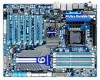
L1/2 LGA1366 FREQ. LED PW_SW ATX RST_SW PHASE LED DDR Voltage LED PWR_FAN GA-X58A-UD9 DDR3_2 USB30_LAN JMicron JMB362 AUDIO F_AUDIO SPDIF_I NEC D720200F1 PCIE_12V_1 NF200 RTL8111E NB_FAN Intel® X58 NB TEMP L1/2 NB Voltage L1/2/3 RTL8111E PCIEX16_1 DDR3_1 DDR3_4 DDR3_3 DDR3_6 DDR3_5 - Gigabyte GA-X58A-UD9 | Manual - Page 8
GA-X58A-UD9 Motherboard Block Diagram 3 PCI Express x8 4 PCI Express x16 CPU CLK+/- (133 MHz) PCIe CLK (100 MHz) LGA1366 CPU DDR3 2200/1333/1066/800 MHz Dual/3 Channel Memory 66/33 IDE Channel x1 GIGABYTE SATA2 QPI Interface IOH CLK (133 MHz) Intel® X58 PCI Express Bus x1 NEC D720200F1 x1 PCIe - Gigabyte GA-X58A-UD9 | Manual - Page 9
manual and follow these procedures: • Prior to installation, do not remove or break motherboard com- ponents such as a motherboard, CPU or memory. If you do not have an system components as well as physical harm to the user. • If you are uncertain about any installation steps or have a problem - Gigabyte GA-X58A-UD9 | Manual - Page 10
(Go to GIGABYTE's website for the latest CPU support list.) L3 cache varies with CPU QPI 4.8GT/s, 6.4GT/s Chipset North Bridge: Intel® X58 Express Chipset South Bridge: Intel® ICH10R Memory 6 x 1.5V DDR3 DIMM sockets supporting up to 24 GB of system memory (Note 1) Dual - Gigabyte GA-X58A-UD9 | Manual - Page 11
3Gb/s devices - Support for SATA RAID 0, RAID 1, and JBOD iTE IT8720 chip: - 1 x floppy disk drive connector supporting up to 1 SATA 3Gb/s connectors w 2 x SATA 6Gb/s connectors w 1 x CPU fan header w 3 x system fan headers w 1 x power fan header w 1 x North Bridge fan header w 1 x front - Gigabyte GA-X58A-UD9 | Manual - Page 12
(OEM version) Operating System w Support for Microsoft® Windows® 7/Vista/XP Form Factor w XL-ATX Form Factor; 34.5cm x 26.2cm (Note 1) Due to Windows 32-bit operating system limitation, when more than 4 GB of physical memory is installed, the actual memory size displayed will be less - Gigabyte GA-X58A-UD9 | Manual - Page 13
the motherboard supports the CPU. (Go to GIGABYTE's website for the latest CPU support list specifications. It is not recommended that the system bus frequency be set beyond hardware specifications since memory, hard drive, etc. 1-3-1 Installing the CPU A. Locate the alignment keys on the motherboard - Gigabyte GA-X58A-UD9 | Manual - Page 14
B. Follow the steps below to correctly install the CPU into the motherboard CPU socket. Before installing the CPU, make sure to turn off the computer and unplug the power cord from the power outlet to prevent damage - Gigabyte GA-X58A-UD9 | Manual - Page 15
to correctly install the CPU cooler on the motherboard. (The following procedure uses Intel® boxed cooler as the example cooler.) Step manual for instructions on installing the cooler.) Step 5: After the installation, check the back of the motherboard. If the push pin is inserted as the picture - Gigabyte GA-X58A-UD9 | Manual - Page 16
your chassis to the F_AUDIO connector on the motherboard, be sure to connect it before installing the North Bridge heasink base. Step 4: The picture on the left shows that four screws are fastened to complete the installation. (Note) For the waterblocks on the North Bridge heatsink, we recommend - Gigabyte GA-X58A-UD9 | Manual - Page 17
guidelines before you begin to install the memory: • Make sure that the motherboard supports the memory. It is recommended that memory of the same capacity, brand, speed, and chips be used. (Go to GIGABYTE's website for the latest supported memory speeds and momery moudles.) • Always turn off - Gigabyte GA-X58A-UD9 | Manual - Page 18
the power cord from the power outlet to prevent damage to the memory module. DDR3 and DDR2 DIMMs are not compatible to each other or DDR DIMMs. Be sure to install DDR3 DIMMs on this motherboard. Notch DDR3 DIMM A DDR3 memory module has a notch, so it can only fit in one direction. Follow - Gigabyte GA-X58A-UD9 | Manual - Page 19
an expansion card: • Make sure the motherboard supports the expansion card. Carefully read the manual that came with your expansion card. • (s). 7. Install the driver provided with the expansion card in your operating system. Example: Installing and Removing a PCI Express Graphics Card: • Installing - Gigabyte GA-X58A-UD9 | Manual - Page 20
Requirements - The 2-Way CrossFireX/SLI technology currently supports Windows XP, Windows Vista, and Windows 7 operating systems - The 3-Way/4-Way CrossFireX/SLI technology currently supports Windows Vista and Windows 7 operating systems only - A CrossFireX/SLI-supported motherboard with two/three - Gigabyte GA-X58A-UD9 | Manual - Page 21
apply. C-2. To Enable SLI Function For 2-Way SLI: After installing the graphics card driver in the operating system, go to the NVIDIA Control Panel. Browse to the Set SLI and PhysX configuration screen and ensure PhysX and SLI are enabled. For 4-Way SLI: Browse to the Set SLI and PhysX configuration - Gigabyte GA-X58A-UD9 | Manual - Page 22
SATA device(s) to your system by expanding the internal SATA port(s) to the chassis back panel. • Turn off your system and the power switch 2: Connect the SATA cable from the bracket to the SATA port on your motherboard. Step 3: Connect the power cable from the bracket to the power supply. Step - Gigabyte GA-X58A-UD9 | Manual - Page 23
an external audio system that supports digital optical audio. Before using this feature, ensure that your audio system provides an optical connector, first remove the cable from your device and then remove it from the motherboard. • When removing the cable, pull it straight out from the connector. Do - Gigabyte GA-X58A-UD9 | Manual - Page 24
USB 3.0/2.0 Port The USB 3.0 port supports the USB 3.0 specification and is compatible to the USB 2.0/1.1 specification MUST be connected to the default Mic in jack ( ). Refer to the instructions on setting up a 2/4/5.1/7.1-channel audio configuration in Chapter 5, "Configuring 2/4/5.1/7.1-Channel - Gigabyte GA-X58A-UD9 | Manual - Page 25
Overvoltage LEDs This motherboard contains 4 sets of overvoltage LEDs which indicate the overvoltage level of the CPU, memory, North Bridge, and (High, red) Overclock LEDs The onboard CPU overclock LEDs indicate on which level the CPU is overclocked. The higher the overclock level, the more - Gigabyte GA-X58A-UD9 | Manual - Page 26
Quick Switches This motherboard has 2 quick buttons: power button and reset button. The power button and reset button allow users to quickly turn on/off or reset the computer - Gigabyte GA-X58A-UD9 | Manual - Page 27
DDR PHASE LED The number of lighted LEDs indicates the memory loading. The higher the memory loading, the more the number of lighted LEDs. - 27 - Hardware Installation - Gigabyte GA-X58A-UD9 | Manual - Page 28
devices. • After installing the device and before turning on the computer, make sure the device cable has been securely attached to the connector on the motherboard. Hardware Installation - 28 - - Gigabyte GA-X58A-UD9 | Manual - Page 29
to all the components on the motherboard. Before connecting the power connector, by the CPU manufacturer when using an Intel Extreme Edition CPU (130W). • To power, the result can lead to an unstable or unbootable system. 8 4 5 1 ATX_12V_2X/ATX_12V_2X_1 ATX_12V_2X/ATX_12V_2X_1: Pin No - Gigabyte GA-X58A-UD9 | Manual - Page 30
orientation (the black connector wire is the ground wire). The motherboard supports CPU fan speed control, which requires the use of a CPU fan with fan speed control design. For optimum heat dissipation, it is recommended that a system fan be installed inside the chassis. 1 CPU_FAN CPU_FAN: Pin No - Gigabyte GA-X58A-UD9 | Manual - Page 31
FDD (Floppy Disk Drive Connector) This connector is used to connect a floppy disk drive. The types of floppy disk drives supported are: 360 KB, 720 KB, 1.2 MB, 1.44 MB, and 2.88 MB. Before connecting a floppy disk drive, be sure to locate pin 1 of the connector and the floppy disk drive cable. The - Gigabyte GA-X58A-UD9 | Manual - Page 32
with SATA 1.5Gb/s stan- dard. Each SATA connector supports a single SATA device. The ICH10R controller supports RAID 0, RAID 1, RAID 5, and RAID 10. Refer to Chapter 5, "Configuring SATA Hard Drive(s)," for instructions on configuring a RAID array. G.QBOFM G.QBOFM PiGn.NQoB.OFMDefinition 1 GND - Gigabyte GA-X58A-UD9 | Manual - Page 33
with SATA 1.5Gb/s standard. Each SATA connector supports a single SATA device. The GIGABYTE SATA2 controller supports RAID 0, RAID 1, and JBOD. Refer to Chapter 5, "Configuring SATA Hard Drive(s)," for instructions on configuring a RAID array. GSATA2_9 7 1 7 1 GSATA2_8 G.QBOFM Pin No - Gigabyte GA-X58A-UD9 | Manual - Page 34
on the chassis front panel. You may configure the way to turn off your system using the power switch (refer to Chapter 2, "BIOS problem is detected at system startup. If a problem is detected, the BIOS may issue beeps in different patterns to indicate the problem. Refer to Chapter 5, "Troubleshooting - Gigabyte GA-X58A-UD9 | Manual - Page 35
The front panel audio header supports Intel High Definition audio (HD) and AC'97 audio. You may connect your chassis front panel audio module to this header. Make sure the wire assignments of the module connector match the pin assignments of the motherboard header. Incorrect connection between the - Gigabyte GA-X58A-UD9 | Manual - Page 36
This header supports digital S/PDIF Out and connects a S/PDIF digital audio cable (provided by expansion cards) for digital audio output from your motherboard to certain digital audio cable, carefully read the manual for your expansion card. 1 Pin No. Definition 1 SPDIFO 2 GND Hardware - Gigabyte GA-X58A-UD9 | Manual - Page 37
2 3 USB DX- G.QBOF4M USB DY- 5 USB DX+ 6 USB DY+ 7 GND 8 GND 9 No Pin 10 NC When the system is in S4/S5 mode, only the USB ports routed to the F_USB1 header can support the ON/OFF Charge function. • Do not plug the IEEE 1394 bracket (2x5-pin) cable into the USB - Gigabyte GA-X58A-UD9 | Manual - Page 38
20) BAT (Battery) The battery provides power to keep the values (such as BIOS configurations, date, and time information) in the CMOS when the computer is turned off. Replace the battery when the battery voltage drops to a low level, or the CMOS values may not be accurate or may be lost. You may - Gigabyte GA-X58A-UD9 | Manual - Page 39
do not encounter problems using the current version of BIOS, it is recommended that you not flash the BIOS. To flash the BIOS, do it with caution. Inadequate BIOS flashing may result in system malfunction. • BIOS will emit a beep code during the POST. Refer to Chapter 5, "Troubleshooting," for the - Gigabyte GA-X58A-UD9 | Manual - Page 40
Inc. Motherboard Model BIOS Version X58A-UD9 E9 . . . . : BIOS Setup : XpressRecovery2 : Boot Menu : Qflash 03/15/2010-X58-ICH10- press to accept. To exit Boot Menu, press . The system will directly boot from the device configured in Boot Menu. Note: The setting in - Gigabyte GA-X58A-UD9 | Manual - Page 41
E9) CMOS Setup Utility-Copyright (C) 1984-2009 Award Software MB Intelligent Tweaker(M.I.T.) Standard CMOS Features Advanced BIOS Features the current submenus Access the Q-Flash utility Display system information Save all the changes and exit the BIOS Setup program - Gigabyte GA-X58A-UD9 | Manual - Page 42
you wish to load, then press to complete. MB Intelligent Tweaker(M.I.T.) Use this menu to configure the clock, frequency and voltages of your CPU, memory, etc. Standard CMOS Features Use this menu to configure the system time and date, hard drive types, floppy disk drive types - Gigabyte GA-X58A-UD9 | Manual - Page 43
: General Help F7: Optimized Defaults Whether the system will work stably with the overclock/overvoltage settings you made is dependent on your overall system configurations. Incorrectly doing overclock/overvoltage may result in damage to CPU, chipset, or memory and reduce the useful life of these - Gigabyte GA-X58A-UD9 | Manual - Page 44
Multi-Threading (Note) Allows you to determine whether to enable multi-threading technology when using an Intel CPU that supports this function. This feature only works for operating systems that support multi-processor mode. (Default: Enabled) CPU Enhanced Halt (C1E) (Note) Enables or disables - Gigabyte GA-X58A-UD9 | Manual - Page 45
fails to boot after overclocking, please wait for 20 seconds to allow for automated system reboot, or clear the CMOS values to reset the board to default values. (Default: Disabled) BCLK Frequency(Mhz) Allows you to manually set the CPU base clock. The adjustable range is from 100 MHz to 600 MHz - Gigabyte GA-X58A-UD9 | Manual - Page 46
adjusted according to the BCLK Frequency(Mhz) and System Memory Multiplier settings. PCI Express Frequency(Mhz) Allows you to manually set the PCIe clock frequency. The adjustable range (Note) This item appears only if you install a memory module that supports this feature. BIOS Setup - 46 - - Gigabyte GA-X58A-UD9 | Manual - Page 47
Exit F1: General Help F7: Optimized Defaults Extreme Memory Profile (X.M.P.) , (Note) System Memory Multiplier (SPD), Memory Frequency(Mhz) The settings under the three items above 1~4. (Note) This item appears only if you install a memory module that supports this feature. - 47 - BIOS Setup - Gigabyte GA-X58A-UD9 | Manual - Page 48
>>>>> Channel A/B Timing Settings CMOS Setup Utility-Copyright (C) 1984-2010 Award Software Channel A Timing Settings >>>>> Channel A Standard Timing Control x CAS Latency Time 7 x tRCD 7 x tRP 7 x tRAS 20 >>>>> Channel A Advanced Timing Control x tRC 28 x tRRD - Gigabyte GA-X58A-UD9 | Manual - Page 49
tFAW Options are: Auto (default), 1~63. Command Rate(CMD) Options are: Auto (default), 1~3. >>>>> Channel A/B Misc Timing Control B2B CAS Delay Options are: Auto (default), 1~31. Round Trip Latency Options are: Auto (default), 1~255. >>>>> Channel A/B/C Turnaround Settings CMOS Setup Utility- - Gigabyte GA-X58A-UD9 | Manual - Page 50
the CPU voltage more constant under light and heavy CPU load. Standard Disables Load-Line Calibration and sets VDroop following Intel specifications. (De- fault) Level 1 Enables Load-Line Calibration and slightly adjusts VDroop. Level 2 Enables Load-Line Calibration and moderately - Gigabyte GA-X58A-UD9 | Manual - Page 51
CPU Vcore The default is Auto. Dynamic Vcore(DVID) This option is configurable only when CPU Vcore is set to Normal. The default is Auto. QPI/Vtt Voltage The default is Auto. CPU PLL The default is Auto. >>>>> MCH/ICH PCIE The default is Auto. QPI PLL The default is Auto. IOH Core The default is - Gigabyte GA-X58A-UD9 | Manual - Page 52
version, CPU base clock, CPU frequency, memory frequency, total memory size , CPU temperature, Chipset temperature, Vcore, and memory voltage. (Note) This item is present only if you install a CPU that supports this feature. For more information about Intel CPUs' unique features, please visit - Gigabyte GA-X58A-UD9 | Manual - Page 53
Extended Memory Total Memory 640K 1022M 1024M Move Enter: Select F5: Previous Values +/-/PU/PD: Value F10: Save F6: Fail-Safe Defaults ESC: Exit F1: General Help F7: Optimized Defaults Date (mm:dd:yy) Sets the system date. The date format is week (read-only), month, date - Gigabyte GA-X58A-UD9 | Manual - Page 54
• None If no IDE/SATA devices are used, set this item to None so the system will skip the detection of the device during the POST for faster system startup. • Manual Allows you to manually enter the specifications of the hard drive when the hard drive access mode is set to - Gigabyte GA-X58A-UD9 | Manual - Page 55
to 3 (Note) No-Execute Memory Protect (Note) Delay For HDD Disk Boot Priority Specifies the sequence of loading the operating system from the installed hard drives. Use the up or down supports this feature. For more information about Intel CPUs' unique features, please visit Intel's website. - Gigabyte GA-X58A-UD9 | Manual - Page 56
Windows NT4.0. (Default: Disabled) No-Execute Memory Protect (Note) Enables or disables Intel Execute Disable Bit function. This function may enhance protection for the computer, reducing exposure to viruses and malicious buffer overflow attacks when working with its supporting software and system - Gigabyte GA-X58A-UD9 | Manual - Page 57
Mode item below will be set to RAID(XHD) automatically. For details on using the GIGABYTE X.H.D utility, refer to Chaper 4, "eXtreme Hard Drive (X.H.D)." (Default: Disabled) ICH SATA Control Mode (Intel ICH10R South Bridge) Enables or disables RAID for the SATA controllers integrated in the - Gigabyte GA-X58A-UD9 | Manual - Page 58
) Enables RAID for the Queuing and hot plug. SATA Port0-3 Native Mode (Intel ICH10R South Bridge) Specifies the operating mode of the integrated option to Disabled if you wish to install operating systems that do not support Native mode. (Default) Enabled Allows the SATA controllers - Gigabyte GA-X58A-UD9 | Manual - Page 59
No LAN Cable Is Attached... If no LAN cable is attached to the motherboard, the Status fields of all four pairs of wires will show Open and of 10/100/1000 Mbps in Windows mode or when the LAN Boot ROM is activated. When a Cable Problem Occurs... If a cable problem occurs on a specified pair of - Gigabyte GA-X58A-UD9 | Manual - Page 60
Marvell 9128 Chip, GSATA3_6/7 Connectors) Allows you to configure RAID for the Marvell 9128 SATA controller. Refer to Chapter 5, "Configuring SATA Hard Drive(s)," for instructions on configuring a RAID array. GSATA 8_9/IDE Controller (GIGABYTE SATA2 Chip, IDE and GSATA2_8/9 Connectors) Enables or - Gigabyte GA-X58A-UD9 | Manual - Page 61
system resumes to its working state exactly where it was left off. Soft-Off by PWR-BTTN Configures the way to system to be awakened from an ACPI sleep state by a wake-up signal from a modem that supports wake-up function. (Default: Enabled) (Note) Supported on Windows 7/Vista operating system - Gigabyte GA-X58A-UD9 | Manual - Page 62
) Allows you to select the HPET mode for your Windows 7/Vista operating system. Select 32-bit mode when you install 32-bit Windows 7/Vista; select 64-bit mode when you install 64-bit Windows 7/Vista. This item is configurable only if the HPET Support is set to Enabled. (Default: 32-bit mode) Power - Gigabyte GA-X58A-UD9 | Manual - Page 63
" at next boot. (Default: Disabled) Case Opened Displays the detection status of the chassis intrusion detection device attached to the motherboard CI header. If the system chassis cover is removed, this field will show "Yes", otherwise it will show "No". To clear the chassis intrusion status record - Gigabyte GA-X58A-UD9 | Manual - Page 64
. Note: The Voltage mode can be set for a 3-pin CPU fan or a 4-pin CPU fan. However, for a 4-pin CPU fan that is not designed following Intel PWM fan specifications, selecting PWM mode may not effectively reduce the fan speed. BIOS Setup - 64 - - Gigabyte GA-X58A-UD9 | Manual - Page 65
In case system instability occurs, you may try to load Fail-Safe defaults, which are the safest and most stable BIOS settings for the motherboard. 2-10 Load Optimized Defaults CMOS Setup Utility-Copyright (C) 1984-2010 Award Software MB Intelligent Tweaker(M.I.T.) - Gigabyte GA-X58A-UD9 | Manual - Page 66
CMOS Setup Utility-Copyright (C) 1984-2010 Award Software MB Intelligent Tweaker(M.I.T.) Standard CMOS Features Advanced BIOS Setup program allows you to specify two separate passwords: Supervisor Password When a system password is set and the Password Check item in Advanced BIOS Features is - Gigabyte GA-X58A-UD9 | Manual - Page 67
to return to the BIOS Setup Main Menu. 2-13 Exit Without Saving CMOS Setup Utility-Copyright (C) 1984-2010 Award Software MB Intelligent Tweaker(M.I.T.) Load Fail-Safe Defaults Standard CMOS Features Advanced BIOS Features Load Optimized Defaults Quit Without Saving (YSe/Nt S)?upNervisor - Gigabyte GA-X58A-UD9 | Manual - Page 68
BIOS Setup - 68 - - Gigabyte GA-X58A-UD9 | Manual - Page 69
. Or click Install Single Items to manually select the drivers you wish to install instructions to restart your system. You can install other applications included in the motherboard driver disk. • For USB 2.0 driver support under the Windows XP operating system, please install the Windows XP Service - Gigabyte GA-X58A-UD9 | Manual - Page 70
applications that GIGABYTE develops and some free software. You can click the Install button on the right of an item to install it. 3-3 Technical Manuals This page provides GIGABYTE's application guides, content descriptions for this driver disk, and the motherboard manuals. Drivers Installation - Gigabyte GA-X58A-UD9 | Manual - Page 71
3-4 Contact For the detailed contact information of the GIGABYTE Taiwan headquarter or worldwide branch offices, click the URL on this page to link to the GIGABYTE website. 3-5 System This page provides the basic system information. - 71 - Drivers Installation - Gigabyte GA-X58A-UD9 | Manual - Page 72
website. The latest version of the BIOS, drivers, or applications will be displayed. 3-7 New Utilities This page provides a quick link to GIGABYTE's lately developed utilities for users to install. You can click the Install button on the right of an item to install it. Drivers Installation - Gigabyte GA-X58A-UD9 | Manual - Page 73
512 MB of system memory • VESA compatible graphics card • Windows XP with SP1 or later, Windows Vista • Xpress Recovery and Xpress Recovery2 are different utilities. For example, a backup file created with Xpress Recovery cannot be restored using Xpress Recovery2. • USB hard drives are not supported - Gigabyte GA-X58A-UD9 | Manual - Page 74
actual size requirements vary, depending on the amount of data) and begin the installation of the operating system. Step 4: After the operating system is the backup file. B. Accessing Xpress Recovery2 1. Boot from the motherboard driver disk to access Xpress Recovery2 for the first time. When - Gigabyte GA-X58A-UD9 | Manual - Page 75
D. Using the Restore Function in Xpress Recovery2 Select RESTORE to restore the backup to your hard drive in case the system breaks down. The RESTORE option will not be present if no backup is created before. E. Removing the Backup Step 1: If you wish to remove the - Gigabyte GA-X58A-UD9 | Manual - Page 76
Award Software, Inc. X58A-UD9 E9 . . . . : BIOS Setup : XpressRecovery2 : Boot Menu : Qflash 03/15/2010-X58-ICH10-7A89QG0MC-00 Because BIOS flashing is potentially risky, please do it with caution. Inadequate BIOS flashing may result in system malfunction. Unique Features - 76 - Gigabyte GA-X58A-UD9 | Manual - Page 77
Save BIOS to Drive Enter : Run hi:Move Total size : 0 ESC:Reset Free size : 0 F10:Power Off 3. Select the BIOS update file and press . Make sure the BIOS update file matches your motherboard model. Step 2: The process of the system reading the BIOS file from the floppy disk is - Gigabyte GA-X58A-UD9 | Manual - Page 78
Setup. Select Load Optimized Defaults and press to load BIOS defaults. System will re-detect all peripheral devices after a BIOS update, so we recommend that CMOS Setup Utility-Copyright (C) 1984-2010 Award Software MB Intelligent Tweaker(M.I.T.) Load Fail-Safe Defaults Standard CMOS - Gigabyte GA-X58A-UD9 | Manual - Page 79
to complete. If the BIOS update file for your motherboard is not present on the @BIOS server site, please manually download the BIOS update file from GIGABYTE's website and follow the instructions in "Update the BIOS without Using the Internet Update Function" below. 2. Update the - Gigabyte GA-X58A-UD9 | Manual - Page 80
that allows users to fine-tune their system settings or do overclock/overvoltage in Windows environment. The user-friendly EasyTune 6 interface also includes tabbed pages for CPU and memory information, letting users read their system-related information without the need to install additional - Gigabyte GA-X58A-UD9 | Manual - Page 81
The Dynamic Energy SaverTM 2 Interface A. Meter Mode In Meter Mode, GIGABYTE Dynamic Energy SaverTM 2 shows how much power they have saved in a Minimize (Application will continue to run in taskbar) 15 INFO/Help 16 Motherboard Phase LED On/Off Switch (Default: On) 17 Live Utility Update ( - Gigabyte GA-X58A-UD9 | Manual - Page 82
Motherboard Phase LED On/Off Switch (Default: On) 16 Live Utility Update (Check for the latest utility version) C. Stealth Mode In Stealth Mode, the system 2: Smart FNA/CPU/VGA/HDD; 3: Smart FNA/CPU/VGA/HDD/Chipset/ Memory. (Note 3) The total amount of power saved will be recorded until re- - Gigabyte GA-X58A-UD9 | Manual - Page 83
on the same network, making full use of Internet resources. Directions for using Q-Share After installing Q-Share from the motherboard driver disk, go to Start>All Programs>GIGABYTE>Q-Share. exe to launch the Q-Share tool. Find the Q-Share icon to configure the data sharing settings. in the - Gigabyte GA-X58A-UD9 | Manual - Page 84
SMART QuickBoost features quick and effortless CPU overclocking for novice and experienced users alike; users simply click on one of the three levels of CPU performance enhancement, and SMART QuickBoost automatically adjusts CPU performance. Instructions: Select a CPU performance boost level and - Gigabyte GA-X58A-UD9 | Manual - Page 85
on PATA and SATA hard drives (partitioned on NTFS file system) in Windows Vista. Instructions: In the main menu, click the Config button to open limit depends on the size of each partition). When this limit is reached, the oldest backup will be ovewritten. Instructions for copying files/folders - Gigabyte GA-X58A-UD9 | Manual - Page 86
Recorder or SMART TimeLock settings. The changed data refers to the data that has been modified, deleted, or newly added since the last backup. The system will make an automatic backup on changed data only once everyday. If the computer is turned on for a long time, the backup will be performed - Gigabyte GA-X58A-UD9 | Manual - Page 87
Enters Power on Suspend mode Enters Suspend to RAM mode Disables this function The Bluetooth dongle included in the motherboard package(Note 2) allows you to wake up the system from Suspend to RAM mode without the need to press the power button first. (Note 1) (Note 2) If your cell - Gigabyte GA-X58A-UD9 | Manual - Page 88
Drive (X.H.D) under the Integrated Peripherals menu to Enabled to enable RAID for the Intel SATA controllers. Step 2: Install the RAID driver and operating system The X.H.D utility supports Windows 7/Vista/XP. Before installing the operating system, you have to load the SATA controller driver first - Gigabyte GA-X58A-UD9 | Manual - Page 89
net- work switch or router device supports the IEEE 802.3ad LACP standard. Please refer to your network switch or router device manual for further details. Select Realtek Ethernet Diagnostic Utility and click Install. Step 1: Insert the motherboard driver disk and select Application Software - Gigabyte GA-X58A-UD9 | Manual - Page 90
Unique Features - 90 - - Gigabyte GA-X58A-UD9 | Manual - Page 91
identical model and capacity). If you do not want to create RAID, you may prepare only one hard drive. • An empty formatted floppy disk. • Windows Vista/XP setup disk. • Motherboard driver disk. 5-1-1 Configuring Intel ICH10R SATA Controllers A. Installing SATA hard drive(s) in your computer Attach - Gigabyte GA-X58A-UD9 | Manual - Page 92
mode correctly in system BIOS Setup. Step 1: Turn on your computer and press to enter BIOS Setup during the POST (Power-On Self-Test). To create RAID, set ICH SATA may differ from the exact settings for your motherboard. The actual BIOS Setup menu options you will see shall depend on the - Gigabyte GA-X58A-UD9 | Manual - Page 93
array. Skip this step and proceed with the installation of Windows operating system for a non-RAID configuration. Step 1: After the POST memory test begins and before the operating system boot begins, look for a message which says "Press to enter Configuration Utility" (Figure 2). Press - Gigabyte GA-X58A-UD9 | Manual - Page 94
Enter>. Then, select a RAID level (Figure 4). RAID levels supported include RAID 0, RAID 1, Recovery, RAID 10, and RAID 5 (the selections available depend -09 Intel Corporation. All Rights Reserved. [ CREATE VOLUME MENU ] Name : Volume0 RAID Level : RAID0(Stripe) Disks : Select Disks Strip Size : - Gigabyte GA-X58A-UD9 | Manual - Page 95
Storage Manager option ROM v8.9.0.1023 PCH-D wRAID5 Copyright(C) 2003-09 Intel Corporation. All Rights Reserved. [ CREATE VOLUME MENU ] Name : Volume0 RAID Level : RAID0(Stripe) Disks : Select Disks Strip Size : 128 MB Capacity : 111.7 GB Sync : N/A Create Volume WARNING : ALL DATA ON SELECTED - Gigabyte GA-X58A-UD9 | Manual - Page 96
RAID array. • By default, only the master drive can be viewed in the operating system; the recovery drive is hidden. Step 1: select Create RAID Volume in MAIN MENU and press (Figure 8). Intel 3JT354CP 3JT329JX Size 111.7GB 111.7GB Type/Status(Vol ID) Non-RAID Disk Non-RAID Disk [hi - Gigabyte GA-X58A-UD9 | Manual - Page 97
data from the master drive to the recovery drive manually using the Update Volume function of the Intel Matrix Storage Console in the operating system. On Request also allows users to restore the master drive to a previous state. Intel(R) Matrix Storage Manager option ROM v8.9.0.1023 PCH-D wRAID5 - Gigabyte GA-X58A-UD9 | Manual - Page 98
a RAID array, select Delete RAID Volume in MAIN MENU and press . In the DELETE VOLUME MENU section, use the up or down arrow key to select the array to be deleted and press . When prompted to confirm your selection (Figure 12), press to confirm or to abort. Intel(R) Matrix - Gigabyte GA-X58A-UD9 | Manual - Page 99
system BIOS Setup. Step 1: Turn on your computer and press to enter BIOS Setup during the POST. In BIOS Setup, go to Integrated Peripherals. To enable RAID, see the table below for configuring different SATA Controllers for RAID. Controller Connectors JMicron eSATA ports JMB362 GIGABYTE - Gigabyte GA-X58A-UD9 | Manual - Page 100
this step and proceed to the installation of Windows operating system for a non-RAID configuration. After the POST memory test begins and before the operating system boot begins, look for a message which says "Press to enter RAID Setup Utility" (Figure 2). Press + to enter the - Gigabyte GA-X58A-UD9 | Manual - Page 101
Array: In the main screen, press on the Create RAID Disk Drive item. Then the Create New RAID screen appears (Figure 4). Gigabyte Technology Corp. RAID Setup Utility v1.07.06 [ Create New RAID ] Name: Level: Disks: Block: Size: GRAID_ 0-Stripe Select Disk 128 KB 240 GB [ Hard Disk - Gigabyte GA-X58A-UD9 | Manual - Page 102
. When prompted to confirm your selection (Figure 7), press to confirm or to abort. Gigabyte Technology Corp. RAID Setup Utility v1.07.06 [ Create New RAID ] Name: Level: Disks: Block: Size: GRAID 0-Stripe Select Disk 128 KB 240 GB [ Hard Disk Drive List ] Model Name } HDD0 - Gigabyte GA-X58A-UD9 | Manual - Page 103
the array information will appear in the center of the screen (Figure 9). Gigabyte Technology Corp. RAID Setup Utility v1.07.06 [ Main Menu ] Create RAID Disk Drive Delete RAID Disk Drive Revert HDD to Non-RAID Solve Mirror Conflict Rebuild Mirror Drive Save And Exit Setup Exit Without Saving - Gigabyte GA-X58A-UD9 | Manual - Page 104
GB Normal Members(HDDx) 01 [fgTAB]-Switch Window [hi]-Select ITEM Figure 10 [ENTER]-Action [ESC]-Exit Now, you may proceed to create the SATA RAID/AHCI driver diskette and the installation of the SATA RAID/ AHCI driver and operating system. Delete the RAID Array: To delete the array, select - Gigabyte GA-X58A-UD9 | Manual - Page 105
controller controls the GSATA3_6/7 ports on the motherboard. Then connect the power connector from your power supply to the hard drive. B. Configuring SATA controller and RAID mode in BIOS Setup Make sure to configure the SATA controller mode correctly in system BIOS Setup. Step 1: Turn on your - Gigabyte GA-X58A-UD9 | Manual - Page 106
as : 1B4B 91A3 B1 1.0.0.1006 2.1.0.1314 2.56Gbps IDE Mode Help Marvell RAID on chip controller. ENTER: Operation F10: Exit/Save ESC: Return Figure 2 the key to select the hard drives to be included in the RAID array. The selected hard drive will be marked with an asterisk (*). After - Gigabyte GA-X58A-UD9 | Manual - Page 107
Disks Free Physical Disks * PD 0: WDC WD800JD-22L * PD 8: WDC WD800JD-22L RAID Level : Max Size (MB) : Stripe Size : Gigabyte Rounding : Quick Init : VD Name : Disks ID : Next RAID 0 152378 64KB 1G Yes Default 0 8 Help Virtual disk configurations. ENTER: Operation F10: Exit - Gigabyte GA-X58A-UD9 | Manual - Page 108
ID : Revision ID : BIOS Version : Firmware Version : PCIe Speed rate : Configure SATA as : 1B4B 91A3 B1 1.0.0.1006 2.1.0.1314 2.56Gbps IDE Mode Help Marvell RAID on chip controller. ENTER: Operation F10: Exit/Save ESC: Return Figure 6 7. Save the Settings and Exit. After you complete the - Gigabyte GA-X58A-UD9 | Manual - Page 109
set up an array or view the current array status in the operating system. To install the utility, insert the motherboard driver disk, then go to Application Software\Install GIGABYTE Utilities and select Marvell Raid Utility to install. Note: After the installation, you must login the utility with - Gigabyte GA-X58A-UD9 | Manual - Page 110
also can copy the SATA controller driver from the motherboard driver disk to a USB flash drive. See the instructions below about how to copy the driver in MS-DOS and Windows mode. In MS-DOS mode: Prepare a startup disk that has CD-ROM support and a blank formatted floppy disk. Steps: 1: Boot from - Gigabyte GA-X58A-UD9 | Manual - Page 111
the menu in Figure 5, • For the Intel ICH10R, select 1) Intel Matrix Storage driver for 32bit system for Windows 32-bit operat- ing system. • For the JMicron JMB362/GIGABYTE SATA2, select 3) GIGABYTE GSATA driver for 32bit system for Windows 32-bit operating system. • For the Marvell 9128 , select - Gigabyte GA-X58A-UD9 | Manual - Page 112
menu similar to Figure 2 below will appear. Select Intel(R) ICH8R/ICH9R/ICH10R/DO/PCH SATA RAID Controller and press . Windows Setup You have chosen to configure a SCSI Adapter for use with Windows, using a device support disk provided by an adapter manufacturer. Select the SCSI - Gigabyte GA-X58A-UD9 | Manual - Page 113
menu similar to Figure 3 below will appear. Select RAID/AHCI Driver for GIGABYTE GBB36X Controller (x32) and press . Windows Setup You have chosen to configure a SCSI Adapter for use with Windows, using a device support disk provided by an adapter manufacturer. Select the SCSI - Gigabyte GA-X58A-UD9 | Manual - Page 114
the Intel ICH10R: Step 1: Restart your system to boot from the Windows Vista setup disk and perform standard OS installation steps. When a screen similar to that below appears (RAID hard drive will not be detected at this stage), select Load Driver (Figure 5). Figure 5 Step 2: Insert the motherboard - Gigabyte GA-X58A-UD9 | Manual - Page 115
3: When a screen as shown in Figure 7 appears, select Intel(R) ICH8R/ICH9R/ICH10R/DO/PCH SATA RAID Controller and click Next. Figure 7 Step 4: After the driver is loaded, select the RAID/AHCI drive(s) where you want to install the operating system and then click Next to continue the OS installation - Gigabyte GA-X58A-UD9 | Manual - Page 116
1: Restart your system to boot from the Windows Vista setup disk and perform standard OS installation steps. When a screen similar to that below appears (RAID/AHCI hard drive(s) will not be detected at this stage), select Load Driver (Figure 9). Figure 9 Step 2: Insert the motherboard driver disk - Gigabyte GA-X58A-UD9 | Manual - Page 117
Step 3: When a screen as shown in Figure 11 appears, select GIGABYTE GBB36X Controller and click Next. Figure 11 Step 4: After the driver is loaded, select the RAID/AHCI drive(s) where you want to install the operating system and then click Next to continue the OS installation (Figure 12). Figure - Gigabyte GA-X58A-UD9 | Manual - Page 118
WMAM9W736333 111.7GB Size 111.7GB T[yEpSeC/S]t-aEtxuist(Vol ID) Member Disk (0) Non-RAID Disk [hi]- RAID volume is being rebuilt). If you do not enable automatic rebuild on this stage, you have to manually rebuild the array in the operating system (see the next page for more details). Intel - Gigabyte GA-X58A-UD9 | Manual - Page 119
the Rebuild in the Operating System While in the operating system, make sure the chipset driver has been installed from the motherboard driver disk. Then launch the Intel Matrix Storage Console from All Programs in the Start menu. Step 1: On the View menu of the Intel Matrix Storage Console, select - Gigabyte GA-X58A-UD9 | Manual - Page 120
Utility. On the RECOVERY OPTIONS menu, select Enable Only Recovery Disk to show the recovery drive in the operating system. Follow the on-screen instructions to complete and exit the RAID Configuration Utility. Intel(R) Matrix Storage Manager option ROM v8.9.0.1023 PCH-D wRAID5 Copyright(C) 2003-09 - Gigabyte GA-X58A-UD9 | Manual - Page 121
SATA2: Turn off your computer and replace the failed hard drive with a new one. Use either the RAID setup utility or the GIGABYTE RAID CONFIGURER utility in the operating system to perform the rebuild. • Rebuilding with the RAID setup utility Step 1: When the message "Press to enter - Gigabyte GA-X58A-UD9 | Manual - Page 122
• Rebuilding in the operating system Make sure the JMicron JMB362/GIGABYTE SATA2 SATA controller driver has been installed from the motherboard driver disk. Launch the GIGABYTE RAID CONFIGURER from All Programs in the Start menu. Step 1: In the GIGABYTE RAID CONFIGURER screen, right-click on the - Gigabyte GA-X58A-UD9 | Manual - Page 123
the rebuild, you must enter the GSATA RAID Configuration menu in BIOS Setup. Step 1: After the system starts, enter the BIOS Setup program and go Rebuild ID : 0 Name : New_VD Status : Degrade Stripe Size : 64K RAID Mode : RAID1 Size : 75776MB BGA Status : N/A Number of PDs : - Gigabyte GA-X58A-UD9 | Manual - Page 124
PD 0: WDC WD800JD-22L PD 8: WDC WD800JD-22L Free Physical Disks Information ID : 0 Name : New_VD Status : Degrade Stripe Size : 64K RAID Mode : RAID1 Size : 75776MB BGA Status : Running BGA Rebuild : 27% Number of PDs : 2 Numbers : 08 Help Virtual Disk: A set of - Gigabyte GA-X58A-UD9 | Manual - Page 125
Audio The motherboard provides six audio jacks on the back panel which support 2/4/5.1/7.1-channel (Note) audio. The picture to the same time. A. Configuring Speakers (The following instructions use Windows Vista as the example operating system.) Step 1: After installing the audio driver, the - Gigabyte GA-X58A-UD9 | Manual - Page 126
Step 2: Connect an audio device to an audio jack. The The current connected device is dialog box appears. Select the device according to the type of device you connect. Then click OK. Step 3: On the Speakers screen, click the Speaker Configuration tab. In the Speaker Configuration list, select - Gigabyte GA-X58A-UD9 | Manual - Page 127
S/PDIF In 1. Installing the S/PDIF In Cable: Step 1: First, attach the connector at the end of the cable to the SPDIF_I header on your motherboard. Step 2: Secure the metal bracket to the chassis back panel with a screw. 2. Configuring S/PDIF In: On the Digital Input screen, click the Default - Gigabyte GA-X58A-UD9 | Manual - Page 128
B. S/PDIF Out The S/PDIF Out jacks can transmit audio signals to an external decoder for decoding to get the best audio quality. 1. Connecting a S/PDIF Out Cable: S/PDIF Coaxial Cable S/PDIF Optical Cable Connect a S/PDIF coaxial cable or a S/PDIF optical cable (either one) to an external decoder - Gigabyte GA-X58A-UD9 | Manual - Page 129
environment . (Note) Install the Dolby GUI Software driver from the motherboard driver disk. Click the Start icon Programs, Dolby Control Center to example.) . Point to All 1. : Click Dolby Pro Logic IIx. The system will expand 2-channel audio for a 7.1-channel surround sound playback. 2. : - Gigabyte GA-X58A-UD9 | Manual - Page 130
5-2-4 Configuring Microphone Recording Step 1: After installing the audio driver, the HD Audio Manager icon will appear in the notification area. Double-click the icon to access the HD Audio Manager. Step 2: Connect your microphone to the Mic in jack (pink) on the back panel or the Mic in jack ( - Gigabyte GA-X58A-UD9 | Manual - Page 131
Step 4: To raise the recording and playback volume for the microphone, click the Microphone Boost icon on the right of the Recording Volume slider and set the Microphone Boost level. Step 5: After completing the settings above, click Start, point to All Programs, point to Accessories, and then click - Gigabyte GA-X58A-UD9 | Manual - Page 132
. Be sure to save the recorded audio file upon completion. B. Playing the Recorded Sound You can play your recording in a digital media player program that supports your audio file format. Appendix - 132 - - Gigabyte GA-X58A-UD9 | Manual - Page 133
5-3 Troubleshooting 5-3-1 Frequently Asked Questions To read more FAQs for your motherboard, please go to the Support&Downloads\Motherboard\FAQ page on GIGABYTE's website. Q: In the BIOS Setup program, why are some BIOS options missing? A: Some advanced options are hidden in the BIOS Setup program - Gigabyte GA-X58A-UD9 | Manual - Page 134
Procedure If you encounter any troubles during system startup, follow the troubleshooting procedure below to solve the problem. START Turn off the power. Remove all peripherals, connecting cables, and power cord etc. Make sure the motherboard does not short-circuit with the chassis or - Gigabyte GA-X58A-UD9 | Manual - Page 135
and solved. END If the procedure above is unable to solve your problem, contact the place of purchase or local dealer for help. Or go to the Support&Downloads\Technical Service Zone page to submit your question. Our customer service staff will reply you as soon as possible. - 135 - Appendix - Gigabyte GA-X58A-UD9 | Manual - Page 136
shadow RAM - Program basic chipset registers Detect memory - Auto-detection of DRAM size, type and ECC Expand compressed BIOS code to appropriate flash R/W codes into the run time area in F000 for ESCD & DMI support Use walking 1's algorithm to check out interface in CMOS circuitry. Also set real- - Gigabyte GA-X58A-UD9 | Manual - Page 137
CMOS setup Example: onboard IDE controller 4. Measure CPU speed Invoke video BIOS 1. Initialize double-byte language font (optional) 2. Put bits for channel 2 Test 8259 functionality Initialize EISA slot 1. Calculate total memory by testing the last double word of each 64K page 2. Program write - Gigabyte GA-X58A-UD9 | Manual - Page 138
keyboard is Early_Reset_KB is not defined Initialize PS/2 Mouse Prepare memory size information for function call: INT 15h ax=E820h Turn on L2 Init HDD write protect 1. Switch back to text mode if full screen logo is supported - If errors occur, report errors & wait for keys - If no errors occur - Gigabyte GA-X58A-UD9 | Manual - Page 139
saving 3. Program boot up speed 4. Chipset final initialization 5. Power management final initialization 6. Clear screen & display summary table 7. Boot BIOS support (popup menu) Update keyboard LED & typematic rate 1. Build MP table 2. Initialize power-saving (optional) 3. Set CMOS century to 20h - Gigabyte GA-X58A-UD9 | Manual - Page 140
GIGABYTE. Our Commitment to Preserving the Environment In addition to high-efficiency performance, all GIGABYTE motherboards local government office, your household waste disposal service or where you purchased the product for user's manual and we will be glad to help you with your effort. Appendix - Gigabyte GA-X58A-UD9 | Manual - Page 141
Finally, we suggest that you practice other environmentally friendly actions by understanding and using the energy-saving features of this product (where applicable), recycling the inner and outer packaging (including shipping containers) this product was delivered in, and by disposing of or - Gigabyte GA-X58A-UD9 | Manual - Page 142
Appendix - 142 - - Gigabyte GA-X58A-UD9 | Manual - Page 143
- 143 - Appendix - Gigabyte GA-X58A-UD9 | Manual - Page 144
Appendix - 144 - - Gigabyte GA-X58A-UD9 | Manual - Page 145
- 145 - Appendix - Gigabyte GA-X58A-UD9 | Manual - Page 146
Appendix - 146 - - Gigabyte GA-X58A-UD9 | Manual - Page 147
- 147 - Appendix - Gigabyte GA-X58A-UD9 | Manual - Page 148
Appendix - 148 - - Gigabyte GA-X58A-UD9 | Manual - Page 149
- 149 - Appendix - Gigabyte GA-X58A-UD9 | Manual - Page 150
Appendix - 150 - - Gigabyte GA-X58A-UD9 | Manual - Page 151
231, Taiwan TEL: +886-2-8912-4000 FAX: +886-2-8912-4003 Tech. and Non-Tech. Support (Sales/Marketing) : http://ggts.gigabyte.com.tw WEB address (English): http://www.gigabyte.com.tw WEB address (Chinese): http://www.gigabyte.tw • G.B.T. INC. - U.S.A. TEL: +1-626-854-9338 FAX: +1-626-854-9339 Tech - Gigabyte GA-X58A-UD9 | Manual - Page 152
.rs • Kazakhstan WEB address : http://www.gigabyte.kz You may go to the GIGABYTE website, select your language in the language list on the top right corner of the website. • GIGABYTE Global Service System To submit a technical or non-technical (Sales/Marketing) question, please link to: http://ggts
-
 1
1 -
 2
2 -
 3
3 -
 4
4 -
 5
5 -
 6
6 -
 7
7 -
8
-
9
-
10
-
11
-
12
-
13
-
14
-
15
-
16
-
17
-
18
-
19
-
20
-
21
-
22
-
23
-
24
-
25
-
26
-
27
-
28
-
29
-
30
-
31
-
32
-
33
-
34
-
35
-
36
-
37
-
38
-
39
-
40
-
41
-
42
-
43
-
44
-
45
-
46
-
47
-
48
-
49
-
50
-
51
-
52
-
53
-
54
-
55
-
56
-
57
-
58
-
59
-
60
-
61
-
62
-
63
-
64
-
65
-
66
-
67
-
68
-
69
-
70
-
71
-
72
-
73
-
74
-
75
-
76
-
77
-
78
-
79
-
80
-
81
-
82
-
83
-
84
-
85
-
86
-
87
-
88
-
89
-
90
-
91
-
92
-
93
-
94
-
95
-
96
-
97
-
98
-
99
-
100
-
101
-
102
-
103
-
104
-
105
-
106
-
107
-
108
-
109
-
110
-
111
-
112
-
113
-
114
-
115
-
116
-
117
-
118
-
119
-
120
-
121
-
122
-
123
-
124
-
125
-
126
-
127
-
128
-
129
-
130
-
131
-
132
-
133
-
134
-
135
-
136
-
137
-
138
-
139
-
140
-
141
-
142
-
143
-
144
-
145
-
146
-
147
-
148
-
149
-
150
-
151
-
152
 |
 |

GA-X58A-UD9
LGA1366 socket motherboard for Intel
®
Core
™
i7 processor family
User's Manual
Rev. 1001
12ME-X58AUD9-1001R