Gigabyte GA-Z68MA-D2H-B3 Manual - Page 29
TPM Trusted Platform Module Header, CLR_CMOS Clearing CMOS Jumper, ing the CMOS values. - clear cmos
 |
UPC - 818313012708
View all Gigabyte GA-Z68MA-D2H-B3 manuals
Add to My Manuals
Save this manual to your list of manuals |
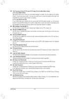
Page 29 highlights
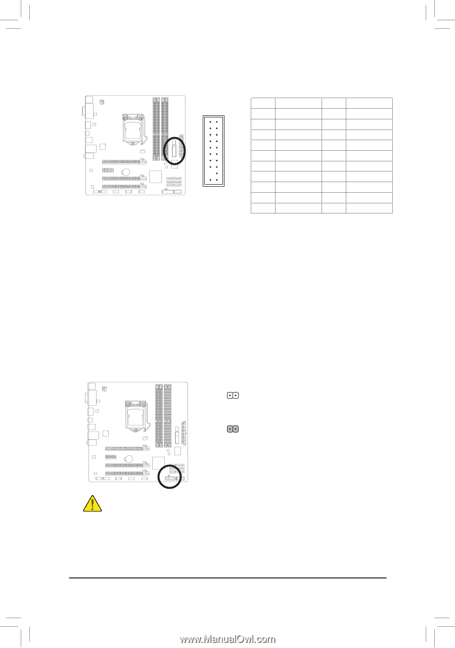
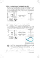
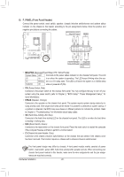
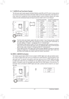
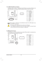
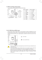
1 DIP 1 23 1 DIP 1 23 1 TPM w/housing Voltage measurement module(X58A-OC) PWM Switch (X58A-OC) DIP 1 23 13) TPM (Trusted Platform Module Header) You may connect a TPM (Trusted Platform Module) to this header. PPiCnIeNpoo.werDceonfinneitciotonr (SATA)(XP58inA-NOoC.) 1 LCLK 11 20 19 2 GND 12 3 LFRAME 13 4 No Pin 14 5 LRESET 15 6 NC 16 2 1 7 LAD3 17 8 LAD2 18 9 VCC3 19 10 LAD1 20 DIP 1 23 Definition LAD0 GND NC ID SB3V SERIRQ GND NC NC SUSCLK 14) CLR_CMOS (Clearing CMOS Jumper) Use this jumper to clear the CMOS values (e.g. date information and BIOS configurations) and reset the CMOS values to factory defaults. To clear the CMOS values, place a jumper cap on the two pins to temporarily short the two pins or use a metal object like a screwdriver to touch the two pins for a few seconds. Open: Normal Short: Clear CMOS Values •• Always turn off your computer and unplug the power cord from the power outlet before clearing the CMOS values. •• After clearing the CMOS values and before turning on your computer, be sure to remove the jumper cap from the jumper. Failure to do so may cause damage to the motherboard. •• After system restart, go to BIOS Setup to load factory defaults (select Load Optimized Defaults) or manually configure the BIOS settings (refer to Chapter 2, "BIOS Setup," for BIOS configurations). - 29 - Hardware Installation
-
 1
1 -
2
-
3
-
4
-
5
-
6
-
7
-
8
-
9
-
10
-
11
-
12
-
13
-
14
-
15
-
16
-
17
-
18
-
19
-
20
-
21
-
22
-
23
-
 24
24 -
 25
25 -
 26
26 -
 27
27 -
 28
28 -
 29
29 -
 30
30 -
 31
31 -
 32
32 -
 33
33 -
 34
34 -
35
-
36
-
37
-
38
-
39
-
40
-
41
-
42
-
43
-
44
-
45
-
46
-
47
-
48
-
49
-
50
-
51
-
52
-
53
-
54
-
55
-
56
-
57
-
58
-
59
-
60
-
61
-
62
-
63
-
64
-
65
-
66
-
67
-
68
-
69
-
70
-
71
-
72
-
73
-
74
-
75
-
76
-
77
-
78
-
79
-
80
-
81
-
82
-
83
-
84
-
85
-
86
-
87
-
88
-
89
-
90
-
91
-
92
-
93
-
94
-
95
-
96
-
97
-
98
-
99
-
100
-
101
-
102
-
103
-
104
 |
 |