Gigabyte GA-Z68XP-UD3 Manual
Gigabyte GA-Z68XP-UD3 Manual
 |
View all Gigabyte GA-Z68XP-UD3 manuals
Add to My Manuals
Save this manual to your list of manuals |
Gigabyte GA-Z68XP-UD3 manual content summary:
- Gigabyte GA-Z68XP-UD3 | Manual - Page 1
GA-Z68XP-UD3-iSSD GA-Z68XP-UD3 User's Manual Rev. 1001 12ME-Z68XPU3-1001R - Gigabyte GA-Z68XP-UD3 | Manual - Page 2
Motherboard GA-Z68XP-UD3-iSSD/GA-Z68XP-UD3 May 31, 2011 Motherboard GA-Z68XP-UD3-iSSD/ GA-Z68XP-UD3 May 31, 2011 - Gigabyte GA-Z68XP-UD3 | Manual - Page 3
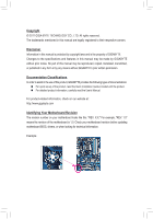
www.gigabyte.com Identifying Your Motherboard Revision The revision number on your motherboard looks like this: "REV: X.X." For example, "REV: 1.0" means the revision of the motherboard is 1.0. Check your motherboard revision before updating motherboard BIOS, drivers, or when looking for technical - Gigabyte GA-Z68XP-UD3 | Manual - Page 4
Optional Items...6 GA-Z68XP-UD3-iSSD/GA-Z68XP-UD3 Motherboard Layout 7 GA-Z68XP-UD3-iSSD/GA-Z68XP-UD3 Motherboard Block Diagram 8 Chapter 1 Hardware Installation 9 1-1 Installation Precautions 9 1-2 Product Specifications 10 1-3 Installing the CPU and CPU Cooler 13 1-3-1 Installing the CPU 13 - Gigabyte GA-Z68XP-UD3 | Manual - Page 5
3-1 Installing Chipset Drivers 61 3-2 Application Software 62 3-3 Technical Manuals 62 3-4 Contact...63 3-5 System...63 3-6 Download Center 64 3-7 New Utilities...64 Chapter 4 Unique Features 65 4-1 Xpress Recovery2 65 4-2 BIOS Update Utilities 68 4-2-1 Updating the BIOS with the - Gigabyte GA-Z68XP-UD3 | Manual - Page 6
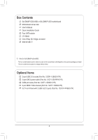
Box Contents GA-Z68XP-UD3-iSSD or GA-Z68XP-UD3 motherboard Motherboard driver disk User's Manual Quick Installation Guide Four SATA cables I/O Shield One 2-Way SLI bridge connector SSD 20 GB j j Only for GA-Z68XP-UD3-iSSD. The box contents above are for reference only and the actual items shall - Gigabyte GA-Z68XP-UD3 | Manual - Page 7
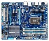
USB_HDMI R_USB30 USB_LAN PWR_FAN ATX AUDIO Etron EJ168 PCIEX1_1 mSATA+SSDj mSATAk DDR3_4 DDR3_2 DDR3_3 DDR3_1 Realtek RTL8111E PCIEX16 PCIEX1_2 CODEC PCIEX1_3 PCIEX8 PCI1 VIA VT6308 PCI2 GA-Z68XP-UD3-iSSD GA-Z68XP-UD3 BAT M_BIOS B_BIOS PCIe to PCI Bridge Intel® Z68 Marvell GSATA3_7 - Gigabyte GA-Z68XP-UD3 | Manual - Page 8
GA-Z68XP-UD3-iSSD/GA-Z68XP-UD3 Motherboard Block Diagram PCIe CLK (100 MHz) 1 PCI Express x16 or 2 PCI Express x8 LGA1155 CPU CPU CLK+/- (100 MHz) DDR3 2133/1866/1600/1333/1066 MHz Dual Channel Memory x16 x8 Switch PCI Express Bus 2 SATA 6Gb/s LAN RJ45 Marvell Realtek 88SE9172 RTL8111E PCI - Gigabyte GA-Z68XP-UD3 | Manual - Page 9
's manual and follow these procedures: •• Prior to installation, do not remove or break motherboard wrist strap when handling electronic com- ponents such as a motherboard, CPU or memory. If you do not have an ESD wrist steps or have a problem related to the use of the product, please consult - Gigabyte GA-Z68XP-UD3 | Manual - Page 10
® processors/Intel® Celeron® processors in the LGA1155 package (Go to GIGABYTE's website for the latest CPU support list.) ŠŠ L3 cache varies with CPU Chipset ŠŠ Intel® Z68 Express Chipset Memory Onboard Graphics Audio ŠŠ 4 x 1.5V DDR3 DIMM sockets supporting up to 32 GB of system memory - Gigabyte GA-Z68XP-UD3 | Manual - Page 11
CMOS jumper ŠŠ 1 x Trusted Platform Module (TPM) header Back Panel ŠŠ 1 x PS/2 keyboard/mouse port Connectors ŠŠ 1 x HDMI port ŠŠ 1 x optical S/PDIF Out connector ŠŠ 1 x IEEE 1394 port ŠŠ 8 x USB 2.0/1.1 ports ŠŠ 2 x USB 3.0/2.0 ports j Only for GA-Z68XP-UD3-iSSD. k Only for GA-Z68XP-UD3 - Gigabyte GA-Z68XP-UD3 | Manual - Page 12
Make sure the monitor cable has been connected to the integrated graphics port on the back panel. Operating System ŠŠ Support for Microsoft® Windows 7/Vista/XP Form Factor ŠŠ ATX Form Factor; 30.5cm x 24.4cm * GIGABYTE reserves the right to make any changes to the product specifications and - Gigabyte GA-Z68XP-UD3 | Manual - Page 13
before you begin to install the CPU: •• Make sure that the motherboard supports the CPU. (Go to GIGABYTE's website for the latest CPU support list.) •• Always turn off the computer and unplug the power cord from the power outlet before installing the CPU to prevent hardware damage. •• Locate the - Gigabyte GA-Z68XP-UD3 | Manual - Page 14
B. Follow the steps below to correctly install the CPU into the motherboard CPU socket. Before installing the CPU, make sure to turn off the computer and unplug the power cord from the power outlet to prevent damage to the CPU. Step 1: Gently press the CPU socket lever handle down and away from the - Gigabyte GA-Z68XP-UD3 | Manual - Page 15
pin. Check that the Male and Female push pins are joined closely. (Refer to your CPU cooler installation manual for instructions on installing the cooler.) Step 5: After the installation, check the back of the motherboard. If the push pin is inserted as the picture above shows, the installation is - Gigabyte GA-Z68XP-UD3 | Manual - Page 16
motherboard provides four DDR3 memory sockets and supports Dual Channel Technology. After the memory is installed, the BIOS Sided, DS=Double-Sided, "- -"=No Memory) DDR3_4 DDR3_2 DDR3_3 DDR3_1 Due to CPU limitations, read the following guidelines before installing the memory in Dual Channel mode. - Gigabyte GA-Z68XP-UD3 | Manual - Page 17
to the memory module. DDR3 and DDR2 DIMMs are not compatible to each other or DDR DIMMs. Be sure to install DDR3 DIMMs on this motherboard. Notch DDR3 DIMM A DDR3 memory module has a notch, so it can only fit in one direction. Follow the steps below to correctly install your memory - Gigabyte GA-Z68XP-UD3 | Manual - Page 18
the motherboard supports the expansion card. Carefully read the manual that came with your expansion card. • Always turn off the computer and unplug the power cord from the power outlet before installing an expansion card to prevent hardware damage. PCI Express x1 Slot PCI Express x16 Slot PCI Slot - Gigabyte GA-Z68XP-UD3 | Manual - Page 19
/SLI-supported motherboard with two PCI Express x16 slots and correct driver - Two CrossFireX/SLI-ready graphics cards of identical brand and chip and correct driver - CrossFireX (Note)/SLI bridge connector(s) - A power supply with sufficient power is recommended (Refer to the manual of - Gigabyte GA-Z68XP-UD3 | Manual - Page 20
USB port supports the USB 2.0/1.1 specification. Use this port for USB devices such as a USB keyboard/mouse, USB printer, USB flash drive and etc. PS/2 Keyboard/Mouse Port Use this port to connect a PS/2 mouse or keyboard. Optical S/PDIF Out Connector This connector provides digital audio motherboard - Gigabyte GA-Z68XP-UD3 | Manual - Page 21
3.0/2.0 Port The USB 3.0 port supports the USB 3.0 specification and is compatible to the USB 2.0/1.1 specification. Use this port for USB devices such as a USB keyboard/mouse, USB printer, USB flash drive and etc. RJ-45 LAN Port The Gigabit Ethernet LAN port provides Internet connection at up to - Gigabyte GA-Z68XP-UD3 | Manual - Page 22
14 3 19 5 2 9 10 7 6 8 4 12 13 14 15 18 11 16 17 20 1) ATX_12V_2X4 2) ATX 3) CPU_FAN 4) SYS_FAN1/2 5) PWR_FAN 6) BAT 7) SATA3_0/1 8) SATA2_2/3/4/5 9) mSATA 10) GSATA3_6/7 11) COMA 12) cable has been securely attached to the connector on the motherboard. Hardware Installation - 22 - - Gigabyte GA-Z68XP-UD3 | Manual - Page 23
ATX (2x2 12V Power Connector and 2x12 Main Power Connector) With the use of the power connector, the power supply can supply enough stable power to all the components on the motherboard . The 12V power connector mainly supplies power to the CPU. If the 12V power connector is not connected, the - Gigabyte GA-Z68XP-UD3 | Manual - Page 24
in damage to the CPU or the system may hang. •• These fan headers are not configuration jumper blocks. Do not place a jumper cap on the headers. 6) BAT (Battery) The battery provides power to keep the values (such as BIOS configurations, date, and time information) in the CMOS when the computer is - Gigabyte GA-Z68XP-UD3 | Manual - Page 25
and are compatible with SATA 1.5Gb/s standard. Each SATA connector supports a single SATA device. The Intel Z68 Chipset supports RAID 0, RAID 1, RAID 5, and RAID 10. Refer to Chapter 5, "Configuring SATA Hard Drive(s)," for instructions on configur- ing a RAID array. G.QBOFM G.QBOFPMin No - Gigabyte GA-Z68XP-UD3 | Manual - Page 26
connector will become unavailable. DB_PORT BIOS Switcher (X58A-OC) 1 M_SATA (X58A-OC) DIP 1 23 PCIe power connector (SATA)(X58A-OC) 10 supports a single SATA device. The Marvell 88SE9172 chip supports RAID 0 and RAID 1. Refer to Chapter 5, "Configuring SATA Hard Drive(s)," for instructions - Gigabyte GA-Z68XP-UD3 | Manual - Page 27
the CMOS values and before turning on your computer, be sure to remove the jumper cap from the jumper. Failure to do so may cause damage to the motherboard. •• After system restart, go to BIOS Setup to load factory defaults (select Load Optimized Defaults) or manually configure the BIOS settings - Gigabyte GA-Z68XP-UD3 | Manual - Page 28
HD- RESRES+ CICI+ PWR+ PWR- Hard Drive Activity LED Reset Switch Power LED Chassis Intrusion Header •• MSG/PWR (Message/ problem is detected at system startup. If a problem is detected, the BIOS may issue beeps in different patterns to indicate the problem. Refer to Chapter 5, "Troubleshooting - Gigabyte GA-Z68XP-UD3 | Manual - Page 29
9 Line Out (L) 10 GND 10 NC DIP 1 23 1 DIP 1 23 1 DIP 1 23 1 BIOS Switcher (X58A-OC) DB_P•O•RTThe front panel audio header supports HD audio by default. If your chassis provides an AC'97 front panel audio module, refer 1to the instructions on how to activate AC'97 functionality via the - Gigabyte GA-Z68XP-UD3 | Manual - Page 30
16 GND DB_PORT BIOS 7 GND 17 SSRX2+ 8 D1- 18 SSRX2- 9 D1+ 19 VBUS 10 NC 20 No Pin When the system is in S4/S5 mode, only the USB ports routed the IEEE 1394 bracket (2x5-pin) cable into the USB 2.0/1.1 header. •• Prior to installing the USB bracket, be sure to turn off your computer and - Gigabyte GA-Z68XP-UD3 | Manual - Page 31
- 7 Power (12V) 8 Power (12V) 9 No Pin 10 GND • Do not plug the USB bracket cable into the IEEE 1394a header. • Prior to installing the IEEE 1394a bracket, be sure to PHASE LED The number of lighted LEDs indicates the CPU loading. The higher the CPU loading, the more the number of lighted LEDs. - Gigabyte GA-Z68XP-UD3 | Manual - Page 32
Header) You may connect a TPM (Trusted Platform Module) to this header. DB_PORT BIOS Switc 1 1 19 TPM w/housing 20 Pin No. Definition 1 LCLK 2 GND PWM Swi DIP 2 Pin No. Definition DIP 11 LAD0 1 23 12 GND PCIe power connector (SATA)(X58A-OC) 13 NC 14 ID 15 SB3V 16 SERIRQ 17 GND 18 - Gigabyte GA-Z68XP-UD3 | Manual - Page 33
latest version of BIOS from the Internet and updates the BIOS. For instructions on using the Q-Flash and @BIOS utilities, refer to Chapter 4, "BIOS Update Utilities." • Because BIOS flashing is potentially risky, if you do not encounter problems using the current version of BIOS, it is recommended - Gigabyte GA-Z68XP-UD3 | Manual - Page 34
when the computer boots. A. The LOGO Screen (Default) B. The POST Screen Award Modular BIOS v6.00PG Copyright (C) 1984-2011, Award Software, Inc. Motherboard Model BIOS Version Z68XP-UD3 F1ax . . . . : BIOS Setup : XpressRecovery2 : Boot Menu : Qflash 05/12/2011-Z68-7A89WG0CC - Gigabyte GA-Z68XP-UD3 | Manual - Page 35
BIOS Version: GA-Z68XP-UD3 Flax) CMOS Setup Utility-Copyright (C) 1984-2011 Award Software MB Intelligent Tweaker(M.I.T.) Standard CMOS Features Advanced BIOS Save & Exit Setup Change CPU's Clock & Voltage F11: Save CMOS to BIOS F12: Load CMOS from BIOS BIOS Setup Program Function Keys - Gigabyte GA-Z68XP-UD3 | Manual - Page 36
, etc. Advanced BIOS Features Use this menu to configure the device boot order, advanced features available on the CPU, and the primary display adapter. Integrated Peripherals Use this menu to configure all peripheral devices, such as SATA, USB, integrated audio, and integrated LAN, etc. Power - Gigabyte GA-Z68XP-UD3 | Manual - Page 37
the overclock/overvoltage settings you made is dependent on your overall system configurations. Incorrectly doing overclock/overvoltage may result in damage to CPU, boot. If this occurs, clear the CMOS values and reset the board to default values.) CMOS Setup Utility-Copyright (C) 1984-2011 Award - Gigabyte GA-Z68XP-UD3 | Manual - Page 38
CPU frequency. (Note 1) This item is present only when you install a memory module that supports this feature. (Note 2) This item is present only when you install a CPU that supports this feature. For more information about Intel CPUs' unique features, please visit Intel's website. BIOS - Gigabyte GA-Z68XP-UD3 | Manual - Page 39
manually configure CPU Turbo ratios in BIOS CPU cores. (Default) 1 Enables only one CPU core. 2 Enables only two CPU cores. 3 Enables only three CPU cores. CPU Multi-Threading (Note) Allows you to determine whether to enable multi-threading technology when using an Intel CPU that supports - Gigabyte GA-Z68XP-UD3 | Manual - Page 40
overclocking, please wait for 20 seconds to allow for automated system reboot, or clear the CMOS values to reset the board to default values. (Default: Disabled) BCLK/DMI/PEG Frequency(0.1MHz) Allows you to manually set the CPU base clock and DMI/PCIe you install a CPU that supports this feature. - Gigabyte GA-Z68XP-UD3 | Manual - Page 41
MHz to 3000 MHz. (Default: Auto) Advanced Memory Settings CMOS Setup Utility-Copyright (C) 1984-2011 Award Software Advanced Memory Settings Extreme dependent on the CPU being used. (Note) This item is present only when you install a memory module that supports this feature. - 41 - BIOS Setup - Gigabyte GA-Z68XP-UD3 | Manual - Page 42
different ranks of the memory to increase memory performance and stability. Auto lets the BIOS automatically configure this setting. (Default: Auto) >>>>> Channel A/B Timing Settings CMOS Setup Utility-Copyright (C) 1984-2011 Award Software Channel A Timing Settings >>>>> Channel A Standard Timing - Gigabyte GA-Z68XP-UD3 | Manual - Page 43
(default), 1~255. Advanced Voltage Settings CMOS Setup Utility-Copyright (C) 1984-2011 Award Software 1.025V [Auto] x Graphics DVID +0.000V Auto >>> MCH/ICH CPU PLL 1.800V [Auto] Item Help Menu Level DRAM Voltage General Help F7: Optimized Defaults - 43 - BIOS Setup - Gigabyte GA-Z68XP-UD3 | Manual - Page 44
CMOS General Help F7: Optimized Defaults >>> CPU Multi-Steps Load-Line Enables or CPU voltage more constant under light and heavy CPU CPU Vcore The default is Auto. Dynamic Vcore(DVID) This option is configurable only when CPU is Auto. >>> MCH/ICH CPU PLL The default is Auto. DRAM Voltage - Gigabyte GA-Z68XP-UD3 | Manual - Page 45
Settings CMOS Setup Utility-Copyright (C) 1984-2011 Award Software Miscellaneous Settings Isochronous Support Isochronous Support Determines whether to enable specific streams within the CPU is present only when you install a CPU that supports this feature. For more information about - Gigabyte GA-Z68XP-UD3 | Manual - Page 46
Utility-Copyright (C) 1984-2011 Award Software Standard CMOS Features Date (mm:dd:yy) Time (hh:mm:ss) Mon, system startup. • Auto Lets the BIOS automatically detect SATA devices during the POST. (Default) • Manual Allows you to manually enter the specifications of the hard - Gigabyte GA-Z68XP-UD3 | Manual - Page 47
hard drive specifications. If you wish to enter the parameters manually, refer to the information on the hard drive. Capacity whether the system will stop for an error during the POST. All Errors Whenever the BIOS detects a non-fatal error the system boot will stop. No Errors The system boot - Gigabyte GA-Z68XP-UD3 | Manual - Page 48
BIOS Features CMOS Setup Utility-Copyright (C) 1984-2011 Award Software Advanced BIOS USB-FDD] [Setup] [Disabled] [Disabled] [Enabled] [0] [Enabled] [PCI list USB-FDD, USB-ZIP, USB-CDROM, USBHDD, Legacy LAN BIOS Setup program. (Note) This item is present only when you install a CPU that supports - Gigabyte GA-Z68XP-UD3 | Manual - Page 49
issue warnings supporting software and system. (Default: Enabled) Delay For HDD (Secs) Allows you to set a delay time for the BIOS PCIE x16 Sets the PCI Express graphics card on the PCIEX16 slot as the first display. PCIE x8 Sets the PCI Express CPU that supports this feature. For more information about - Gigabyte GA-Z68XP-UD3 | Manual - Page 50
that do not support Native mode. Enabled Allows the SATA controllers to operate in Native IDE mode. Enable Native IDE mode if you wish to install operating systems that support Native mode. (Default) j Only for GA-Z68XP-UD3-iSSD. k Only for GA-Z68XP-UD3. BIOS Setup - 50 - Gigabyte GA-Z68XP-UD3 | Manual - Page 51
LAN cable: When No LAN Cable Is Attached... If no LAN cable is attached to the motherboard, the Status fields of all four pairs of wires will show Open and the Length fields show 0m, as shown in the figure above. When LAN Cable Is Functioning Normally... If no cable problem is detected on the LAN - Gigabyte GA-Z68XP-UD3 | Manual - Page 52
LAN Boot ROM is activated. When a Cable Problem Occurs... If a cable problem LAN cable. Onboard LAN Boot ROM Allows you to decide whether to activate the boot ROM integrated with the onboard LAN chip. (Default: Disabled) R_USB30 Controller (Etron EJ168 USB Controller, USB driver BIOS Setup - 52 - - Gigabyte GA-Z68XP-UD3 | Manual - Page 53
for less than 4 seconds, the system will enter suspend mode. PME Event Wake Up Allows the system to be awakened from an ACPI sleep state by a wake-up signal from a PCI or PCIe device. Note: To use this function, you need an ATX power supply providing at least 1A on the +5VSB lead. (Default: Enabled - Gigabyte GA-Z68XP-UD3 | Manual - Page 54
Allows the system to be turned on by a PS/2 keyboard wake-up event. Note: you need an ATX power supply providing at least 1A on the +5VSB lead. PME event wake up, power on by mouse, power on by keyboard, and wake on LAN. (Note) Supported on Windows 7/Vista operating system only. BIOS Setup - - Gigabyte GA-Z68XP-UD3 | Manual - Page 55
CMOS Setup Utility-Copyright (C) 1984-2011 Award Software PC Health Status Reset Case Open Status Case Opened Vcore DDR15V +12V Vcc3 Vcc Vtt Current System Temperature Current CPU Temperature Current CPU device attached to the motherboard CI header. If - Gigabyte GA-Z68XP-UD3 | Manual - Page 56
FAN Control is set to Manual. Options are: 0.75 PWM value /oC ~ 2.50 PWM value /oC. CPU Smart FAN Mode Specifies how to control CPU fan speed. This item is configurable only when CPU Smart FAN Control is enabled. Auto Lets the BIOS automatically detect the type of CPU fan installed and sets the - Gigabyte GA-Z68XP-UD3 | Manual - Page 57
system instability occurs, you may try to load Fail-Safe defaults, which are the safest and most stable BIOS settings for the motherboard. 2-10 Load Optimized Defaults CMOS Setup Utility-Copyright (C) 1984-2011 Award Software MB Intelligent Tweaker(M.I.T.) Load Fail-Safe Defaults Standard - Gigabyte GA-Z68XP-UD3 | Manual - Page 58
Save & Exit Setup Exit Without Saving ESC: Quit F8: Q-Flash Select Item F10: Save & Exit Setup Change/Set/Disable Password F11: Save CMOS to BIOS F12: Load CMOS from BIOS Press on this item and type the password with up to 8 characters and then press . You will be requested to - Gigabyte GA-Z68XP-UD3 | Manual - Page 59
Power Management Setup Save & Exit Setup PC Health Status Exit Without Saving ESC: Quit F8: Q-Flash Select Item F10: Save & Exit Setup Save Data to CMOS F11: Save CMOS to BIOS F12: Load CMOS from BIOS Press on this item and press the key. This saves the changes to the - Gigabyte GA-Z68XP-UD3 | Manual - Page 60
BIOS Setup - 60 - - Gigabyte GA-Z68XP-UD3 | Manual - Page 61
install the utilities. Or click No if you want to manually select the utilities to install on the Application Software page later. • For USB 2.0 driver support under the Windows XP operating system, please install the Windows XP Service Pack 1 or later. After installing the SP1 (or later), if - Gigabyte GA-Z68XP-UD3 | Manual - Page 62
that GIGABYTE develops and some free software. You can click the Install button on the right of an item to install it. 3-3 Technical Manuals This page provides GIGABYTE's application guides, content descriptions for this driver disk, and the motherboard manuals. Drivers Installation - 62 - - Gigabyte GA-Z68XP-UD3 | Manual - Page 63
3-4 Contact For the detailed contact information of the GIGABYTE Taiwan headquarter or worldwide branch offices, click the URL on this page to link to the GIGABYTE website. 3-5 System This page provides the basic system information. - 63 - Drivers Installation - Gigabyte GA-Z68XP-UD3 | Manual - Page 64
3-6 Download Center To update the BIOS, drivers, or applications, click the Download Center button to link to the GIGABYTE website. The latest version of the BIOS, drivers, or applications will be displayed. 3-7 New Utilities This page provides a quick link to GIGABYTE's lately developed utilities - Gigabyte GA-Z68XP-UD3 | Manual - Page 65
recommended to back up your system soon after the operating system and drivers are installed. • The amount of data and hard drive access speed may USB hard drives are not supported. • RAID drives are not supported. • GPT partitions are not supported. • Hard drives larger than 2.2 TB are not supported - Gigabyte GA-Z68XP-UD3 | Manual - Page 66
note that if there is no enough unallocated space, Xpress Recovery2 cannot save the backup file. B. Accessing Xpress Recovery2 1. Boot from the motherboard driver disk to access Xpress Recovery2 for the first time. When you see the following message: Press any key to startup Xpress Recovery2, press - Gigabyte GA-Z68XP-UD3 | Manual - Page 67
D. Using the Restore Function in Xpress Recovery2 Select RESTORE to restore the backup to your hard drive in case the system breaks down. The RESTORE option will not be present if no backup is created before. E. Removing the Backup Step 1: If you wish to remove the backup file, select REMOVE. Step - Gigabyte GA-Z68XP-UD3 | Manual - Page 68
A. Before You Begin 1. From GIGABYTE's website, download the latest compressed BIOS update file that matches your motherboard model. 2. Extract the file and save the new BIOS file (e.g. z68xpud3.f1) to your USB flash drive, or hard drive. Note: The USB flash drive or hard drive must use FAT32/16/12 - Gigabyte GA-Z68XP-UD3 | Manual - Page 69
Enter : Run hi:Move Total size : 0 ESC:Reset Free size : 0 F10:Power Off 3. Select the BIOS update file and press . Make sure the BIOS update file matches your motherboard model. Step 2: The process of the system reading the BIOS file from the USB flash drive is displayed on the screen - Gigabyte GA-Z68XP-UD3 | Manual - Page 70
Setup. Select Load Optimized Defaults and press to load BIOS defaults. System will re-detect all peripheral devices after a BIOS update, so we recommend that you reload BIOS defaults. CMOS Setup Utility-Copyright (C) 1984-2011 Award Software MB Intelligent Tweaker(M.I.T.) Load Fail-Safe - Gigabyte GA-Z68XP-UD3 | Manual - Page 71
. If the BIOS update file for your motherboard is not present on the @BIOS server site, please manually download the BIOS update file from GIGABYTE's website and follow the instructions in "Update the BIOS without Using the Internet Update Function" below. 2. Update the BIOS without Using the - Gigabyte GA-Z68XP-UD3 | Manual - Page 72
Available functions in EasyTune 6 may differ by motherboard model. Grayed-out area(s) indicates that the item is not configurable or the function is not supported. Incorrectly doing overclock/overvoltage may result in damage to the hardware components such as CPU, chipset, and memory and reduce the - Gigabyte GA-Z68XP-UD3 | Manual - Page 73
2 Current CPU Power Consumption 3 Power Saving (Calculate power savings based on time) 4 Meter Time 5 Meter/Timer Reset Switch 6 Utility Update (Check for the latest utility version) • The above data is for reference only. Actual performance may vary depending on motherboard model. • CPU - Gigabyte GA-Z68XP-UD3 | Manual - Page 74
) 13 INFO/Help 14 Motherboard Phase LED On/Off Switch (Default: On) 15 Live Utility Update (Check for the latest CPU Enhanced Halt (C1E) and CPU EIST Function items in the BIOS Setup program are set to Enabled. (Note 2) 1: Smart FAN/CPU (default); 2: Smart FAN/CPU/VGA/HDD; 3: Smart FAN/CPU - Gigabyte GA-Z68XP-UD3 | Manual - Page 75
LAN connection settings and Q-Share, you are able to share your data with computers on the same network, making full use of Internet resources. Directions for using Q-Share After installing Q-Share from the motherboard driver folder to be shared (Note) Updates Q-Share online Displays the current - Gigabyte GA-Z68XP-UD3 | Manual - Page 76
the three levels of CPU performance enhancement, and SMART QuickBoost automatically adjusts CPU performance. Instructions: Select a CPU performance boost level and restart your computer for the changes to take effect. Whether SMART QuickBoost is supported depends on the motherboard model. Unique - Gigabyte GA-Z68XP-UD3 | Manual - Page 77
your files from the backup image System Recovery... Allows you to recover your system from the backup image • Supported operating systems: Windows 7 and Vista. • Smart Recovery 2 only supports NTFS file system. • You need to select the destination partition in Settings the first time you use Smart - Gigabyte GA-Z68XP-UD3 | Manual - Page 78
, and remind users of the dates. It also stores the recorded data in the main and backup BIOS simultaneously, which can prevent loss of the data in case the system/hard drive fails. Instructions: Enter the Smart 6™ password to launch the SMART DualBIOS utility. You can record personal passwords and - Gigabyte GA-Z68XP-UD3 | Manual - Page 79
were moved within the hard drive or copied to an external storage device (Note 2). Instructions: Select the Enable check box at the bottom of the ON/OFF Recorder or File the User Password in the system BIOS Setup program to prevent the system time being changed by other users. - 79 - Unique - Gigabyte GA-Z68XP-UD3 | Manual - Page 80
Power on Suspend mode Suspend Enters Suspend to RAM mode Disable Disables this function The Bluetooth dongle included in the motherboard package(Note 2) allows you to wake up the system from Suspend to RAM mode without the need to press the power button first. (Note 1) (Note 2) If - Gigabyte GA-Z68XP-UD3 | Manual - Page 81
All button to automatically install all motherboard drivers, including the X.H.D utility. Or you can go to the Application Software screen to individually install the X.H.D utility later. B. Using GIGABYTE eXtreme Hard Drive (X.H.D) Instructions: (Note 2) Before launching X.H.D, make sure the - Gigabyte GA-Z68XP-UD3 | Manual - Page 82
, CPU VCore and system temperature. • Control (System Status Control): The Control tab allows for controlling system power states with restart, power off, suspend, and hibernate options. (Note 1) (Note 2) (Note 3) Supported on Windows 7, Vista, and XP. For Windows XP, be sure to update Internet - Gigabyte GA-Z68XP-UD3 | Manual - Page 83
voltages. Allows you to configure Advanced BIOS Features. Enables QuickBoost utility. Provides quick and effortless CPU overclocking for novice and experienced users alike. Loads Optimized Defaults. Sets Supervisor Password. Enables @BIOS utility to update the BIOS. - 83 - Unique Features - Gigabyte GA-Z68XP-UD3 | Manual - Page 84
Unique Features - 84 - - Gigabyte GA-Z68XP-UD3 | Manual - Page 85
BIOS Setup. C. Configure a RAID array in RAID BIOS. (Note 1) D. Install the SATA RAID/AHCI driver 7/Vista/XP setup disk. • Motherboard driver disk. • A USB floppy disk drive (needed during Windows motherboard, the SATA3_0, SATA3_1 (Note 3), SATA2_2, SATA2_3, SATA2_4 and SATA2_5 ports are supported - Gigabyte GA-Z68XP-UD3 | Manual - Page 86
USB Controllers USB Legacy Function USB Storage Function Azalia Codec Onboard H/W 1394 Onboard H/W LAN } SMART LAN Onboard LAN exit BIOS Setup. The BIOS Setup menus described in this section may differ from the exact settings for your motherboard. The actual BIOS Setup menu - Gigabyte GA-Z68XP-UD3 | Manual - Page 87
C. Configuring a RAID array in RAID BIOS Enter the RAID BIOS setup utility to configure a RAID array. Skip this step All Rights Reserved. [ MAIN MENU ] 1. Create RAID Volume 2. Delete RAID Volume 3. Reset Disks to Non-RAID 4. Recovery Volume Options 5. Acceleration Options 6. Exit RAID Volumes : - Gigabyte GA-Z68XP-UD3 | Manual - Page 88
with 1~16 letters (letters cannot be special characters) under the Name item and press . Then, select a RAID level (Figure 4). RAID levels supported include RAID 0, RAID 1, Recovery, RAID 10, and RAID 5 (the selections available depend on the number of the hard drives being installed). Press - Gigabyte GA-Z68XP-UD3 | Manual - Page 89
Reserved. [ MAIN MENU ] 1. Create RAID Volume 2. Delete RAID Volume 3. Reset Disks to Non-RAID 4. Recovery Volume Options 5. Acceleration Options 6. Exit RAID [ESC]-Exit Figure 7 [ENTER]-Select Menu To exit the RAID BIOS utility, press or select 6. Exit in MAIN MENU. Now, you can proceed - Gigabyte GA-Z68XP-UD3 | Manual - Page 90
ROM - 10.5.0.1034 Copyright(C) 2003-11 Intel Corporation. All Rights Reserved. [ MAIN MENU ] 1. Create RAID Volume 2. Delete RAID Volume 3. Reset Disks to Non-RAID 4. Recovery Volume Options 5. Acceleration Options 6. Exit RAID Volumes : None defined. [ DISK/VOLUME INFORMATION ] Physical Disks - Gigabyte GA-Z68XP-UD3 | Manual - Page 91
. On Request allows users to update data from the master drive to the recovery drive manually using the Intel Rapid Storage Technology ] Select a sync option: On Request: volume is updated manually Continuous: volume is updated automatically [hi]-Change [TAB]-Next [ESC]-Previous Menu Figure - Gigabyte GA-Z68XP-UD3 | Manual - Page 92
tEoLdPel]ete "Volume0"? (Y/N) : * = Accelerated Volume Deleting a volume will reset the disks to non-RAID. WARNING: ALL DISK DATA WILL BE DELETED. ( an application error or operating system issue, you will need to remove acceleration or manually enable synchronization (Maximized mode only) using - Gigabyte GA-Z68XP-UD3 | Manual - Page 93
USB Controllers USB Legacy Function USB Storage Function Azalia Codec Onboard H/W 1394 Onboard H/W LAN } SMART LAN Onboard LAN exit BIOS Setup. The BIOS Setup menus described in this section may differ from the exact settings for your motherboard. The actual BIOS Setup menu - Gigabyte GA-Z68XP-UD3 | Manual - Page 94
to enter the RAID setup utility. Marvell 88SE91xx Adapter - BIOS Version 1.0.0.0017 PCIe x2 5.0Gbps Mode: RAID [Virtual Disks] No Virtual Disk! 0 Marvell BIOS Setup (c) 2009 Marvell Technology Group Ltd. [ Adapter] [ Devices] [ RAID ] Vendor ID Device ID: BIOS Version: PCI Slot: - Gigabyte GA-Z68XP-UD3 | Manual - Page 95
screen, press on the RAID tab. Then the RAID Config menu appears (Figure 4). Press on the Create VD item. Marvell BIOS Setup (c) 2009 Marvell Technology Group Ltd. [ Selection] [ Adapter] [ Devices] [ RAID ] RAID Config Create VD Delete VD Wipe out disk Spare Management ENTER - Gigabyte GA-Z68XP-UD3 | Manual - Page 96
write-back or write-through cache. 5. VD Name: Enter an array name with 1~10 letters (letters cannot be special characters). Marvell BIOS Setup (c) 2009 Marvell Technology Group Ltd. [ Selection] [ Adapter] [ Devices] [ RAID ] Select free disks to create PCorrteate VD Disk Name * S0 * S1 - Gigabyte GA-Z68XP-UD3 | Manual - Page 97
the message "Do you want to delete the VD's MBR?" appears, press to clear the MBR or press other keys to ignore. Marvell BIOS Setup (C) 2009 Marvell Technology Group Ltd. [ Selection] [ Adapter] [ Devices] [ RAID ] RAID Config Delete VD ID * 0 Name GBT Size 152.4GB Level RAID0 Status - Gigabyte GA-Z68XP-UD3 | Manual - Page 98
utility, you can set up an array or view the current array status in the operating system. To install the utility, insert the motherboard driver disk, then go to Application Software\Install Application Software and select Marvell Storage Utility to install. Note: After the installation, you must - Gigabyte GA-Z68XP-UD3 | Manual - Page 99
Driver and Operating System With the correct BIOS settings, you are ready to install Windows 7/Vista/XP. A. Installing Windows 7/Vista (The following instructions installed, we recommend that you install all required drivers from the motherboard driver disk using "Xpress Install" to ensure system - Gigabyte GA-Z68XP-UD3 | Manual - Page 100
folder. Method B: Steps: 1: Use an alternative system and insert the motherboard driver disk. 2: From your optical drive folder, double click the Menu. (if you're using a USB floppy disk drive, make sure it is designated as drive A). Select the controller driver by pressing the corresponding letter - Gigabyte GA-Z68XP-UD3 | Manual - Page 101
/AHCI driver and press . Then a controller menu similar to that in Figure 3 will appear. Select Intel(R) Desktop/Workstation/Server Express Chipset using a device support disk provided by an adapter manufacturer. Select the SCSI Adapter you want from the following list, or press ESC - Gigabyte GA-Z68XP-UD3 | Manual - Page 102
screen, press to continue the driver installation. Windows Setup You have chosen to configure a SCSI Adapter for use with Windows, using a device support disk provided by an adapter manufacturer. Select the SCSI Adapter you want from the following list, or press ESC to return to the - Gigabyte GA-Z68XP-UD3 | Manual - Page 103
). If you do not enable automatic rebuild on this stage, you have to manually rebuild the array in the operating system (see the next page for more details . All Rights Reserved. 1. Create RAID Volume 2. Delete RAID Volume 3. Reset Disks to Non-RAID [ MAIN MENU ] 4. Recovery Volume Options 5. - Gigabyte GA-Z68XP-UD3 | Manual - Page 104
• Performing the Rebuild in the Operating System While in the operating system, make sure the Chipset driver has been installed from the motherboard driver disk. Then launch the Intel Rapid Storage Technology utility from All Programs in the Start menu. Step 1: Go to the Manage menu and click - Gigabyte GA-Z68XP-UD3 | Manual - Page 105
Recovery Volume only) When two hard drives are set to Recovery Volume in Update on Request mode, you can restore the master drive data to the last the recovery drive in the operating system. Follow the on-screen instructions to complete and exit the RAID Configuration Utility. Intel(R) Rapid - Gigabyte GA-Z68XP-UD3 | Manual - Page 106
set the new hard drive as a Spare drive in the RAID setup utility first. • Enabling Automatic Rebuild Step 1: When the message "Press + to enter BIOS Setup or to continue" appears, press + to enter the RAID setup utility. On the main screen, press on the RAID tab - Gigabyte GA-Z68XP-UD3 | Manual - Page 107
you have installed the Marvell RAID driver and Marvell Storage Utility from the motherboard driver disk. While in the operating system completed, the status will display as Done. • Manually Rebuilding RAID 1 in the Operating System You can manually rebuild a RAID 1 array without setting the new - Gigabyte GA-Z68XP-UD3 | Manual - Page 108
jack and manually configure the jack for microphone functionality. • Audio signals will be present on both of the front and back panel audio connections simultaneously. If you want to mute the back panel audio (only supported when using an HD front panel audio module), refer to instructions on the - Gigabyte GA-Z68XP-UD3 | Manual - Page 109
tab. In the Speaker Configuration list, select Stereo, Quadraphonic, 5.1 Speaker, or 7.1 Speaker according to the type of speaker configuration you wish to set up. Then the speaker setup is completed. B. Configuring Sound Effect You may configure an audio environment on the Sound Effects tab - Gigabyte GA-Z68XP-UD3 | Manual - Page 110
Connect a S/PDIF optical cable to the corresponding S/PDIF out connector as shown below and an external decoder for transmitting the S/PDIF digital audio signals. Connects to a S/PDIF optical cable 2. Configuring S/PDIF Out: On the Digital Output(Optical) screen , (Note) click the Default Format tab - Gigabyte GA-Z68XP-UD3 | Manual - Page 111
, you get only 2-channel playback output (from the front speakers) when playing 2-channel stereo sources. You must play 4-, 5.1-, or 7.1- channel content to get 4-, 5.1-, or 7.1- channel audio effects. With Dolby Home Theater enabled, 2-channel stereo content will be transformed into multi-channel - Gigabyte GA-Z68XP-UD3 | Manual - Page 112
5-2-4 Configuring Microphone Recording Step 1: After installing the audio driver, the HD Audio Manager icon will appear in the notification area. Double-click the icon to access the HD Audio Manager. Step 2: Connect your microphone to the Mic in jack (pink) on the back panel or the Mic in jack ( - Gigabyte GA-Z68XP-UD3 | Manual - Page 113
, click Start, point to All Programs, point to Accessories, and then click Sound Recorder to begin the sound recording. * Enabling Stereo Mix If the HD Audio Manager does not display the recording device you wish to use, refer to the steps below. The following steps explain how to enable Stereo Mix - Gigabyte GA-Z68XP-UD3 | Manual - Page 114
Start Recording button . 3. To stop recording audio, click the Stop Recording button . Be sure to save the recorded audio file upon completion. B. Playing the Recorded Sound You can play your recording in a digital media player program that supports your audio file format. Appendix - 114 - - Gigabyte GA-Z68XP-UD3 | Manual - Page 115
driver from the motherboard driver disk or download the audio driver from GIGABYTE's website to install. For more details, go to the Support & Downloads\FAQ page on our website and search for "onboard HD audio driver." Q: What do the beeps emitted during the POST mean? A: The following Award BIOS - Gigabyte GA-Z68XP-UD3 | Manual - Page 116
Procedure If you encounter any troubles during system startup, follow the troubleshooting procedure below to solve the problem. START Turn off the power. Remove all peripherals, connecting cables, and power cord etc. Make sure the motherboard does not short-circuit with the chassis or - Gigabyte GA-Z68XP-UD3 | Manual - Page 117
"Save & Exit Setup" to save changes and exit BIOS Setup. The problem is verified and solved. Turn off the computer and connect problem, contact the place of purchase or local dealer for help. Or go to the Support & Downloads\Technical Support page to submit your question. Our customer service - Gigabyte GA-Z68XP-UD3 | Manual - Page 118
Appendix - 118 - - Gigabyte GA-Z68XP-UD3 | Manual - Page 119
Bao Chiang Road, Hsin-Tien Dist., New Taipei City 231,Taiwan TEL: +886-2-8912-4000 FAX: +886-2-8912-4003 Tech. and Non-Tech. Support (Sales/Marketing) : http://ggts.gigabyte.com.tw WEB address (English): http://www.gigabyte.com WEB address (Chinese): http://www.gigabyte.tw • G.B.T. INC. - U.S.A. TEL - Gigabyte GA-Z68XP-UD3 | Manual - Page 120
WEB address : http://www.gigabyte.kz You may go to the GIGABYTE website, select your language in the language list on the top right corner of the website. • GIGABYTE Global Service System To submit a technical or non-technical (Sales/Marketing) question, please link to: http://ggts.gigabyte.com.tw
-
 1
1 -
 2
2 -
 3
3 -
 4
4 -
 5
5 -
 6
6 -
 7
7 -
8
-
9
-
10
-
11
-
12
-
13
-
14
-
15
-
16
-
17
-
18
-
19
-
20
-
21
-
22
-
23
-
24
-
25
-
26
-
27
-
28
-
29
-
30
-
31
-
32
-
33
-
34
-
35
-
36
-
37
-
38
-
39
-
40
-
41
-
42
-
43
-
44
-
45
-
46
-
47
-
48
-
49
-
50
-
51
-
52
-
53
-
54
-
55
-
56
-
57
-
58
-
59
-
60
-
61
-
62
-
63
-
64
-
65
-
66
-
67
-
68
-
69
-
70
-
71
-
72
-
73
-
74
-
75
-
76
-
77
-
78
-
79
-
80
-
81
-
82
-
83
-
84
-
85
-
86
-
87
-
88
-
89
-
90
-
91
-
92
-
93
-
94
-
95
-
96
-
97
-
98
-
99
-
100
-
101
-
102
-
103
-
104
-
105
-
106
-
107
-
108
-
109
-
110
-
111
-
112
-
113
-
114
-
115
-
116
-
117
-
118
-
119
-
120
 |
 |

GA-Z68XP-UD3-iSSD
GA-Z68XP-UD3
User's Manual
Rev. 1001
12ME-Z68XPU3-1001R