Gigabyte MDQ17AI Manual
Gigabyte MDQ17AI Manual
 |
View all Gigabyte MDQ17AI manuals
Add to My Manuals
Save this manual to your list of manuals |
Gigabyte MDQ17AI manual content summary:
- Gigabyte MDQ17AI | Manual - Page 1
MDQ17AI Quick Reference Guide 1 2 3 4 5 6 7 8 9 10 11 12 13 14 38 15 37 16 You can use this port to connect your HDMI-supported monitor. The maximum supported resolution is 4096x2160@24Hz or 2560x1600@60Hz, but the actual resolutions supported are dependent on the monitor being used. Speed
-
 1
1
 |
 |
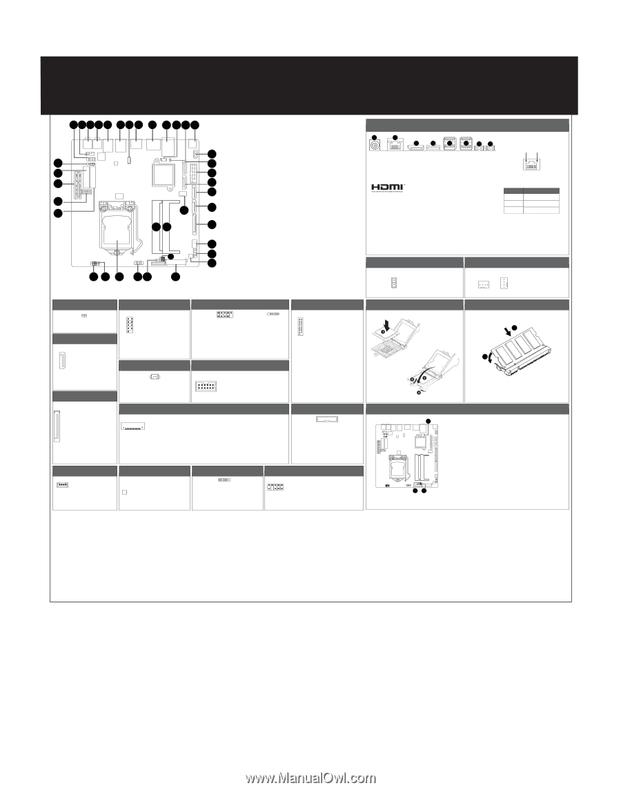
MDQ17AI Quick Reference Guide/
快速测试参考指南
No.
Code
Descrip°on
1
FP_AUDIO
Front audio header
2
SPKR
Speaker cable connector
3
MIC_IN
Audio Mic In port
4
LINE_OUT
Audio Line Out port
5
USB3_2
USB 3.0 ports
6
USB3_1
USB 3.0 ports
7
NFC
NFC connector
8
HDMI
HDMI port
9
DP
Display port connector
10
LAN
GbE LAN port
11
BATTERY
B
a±ery cable connector
12
CLR_CMOS
Clear CMOS jumper
13
DC_IN
DC In power connector
14
ATX_19V
2 pin power connector
15
SATAIII_3
SATA 6Gb/s connector
16
FUSB3_1
USB 3.0 header
17
SATAIII_2
SATA 6Gb/s connector
18
SATAIII_1
SATA 6Gb/s connector
19
SATAIII_0
SATA 6Gb/s connector
20
SATA_PWR
Hard disk power connector
21
CPU_FAN
CPU fan connector
22
SYS_PANEL
Front panel header
23
MON_SW
Monitor power switch header
24
SYS_FAN
System fan connector
25
SODIMM2
DDR3L SO-DIMM slot#2
26
SODIMM1
DDR3L SO-DIMM slot#1
27
FPD_PWR
LVDS power select jumper (12V/19V/top)
LCD_VCC
LVDS Drive voltage jumper (bo±om)
28
LVDS
LVDS connector
29
BL_SW
Back light brightness switch
30
FUSB2_3
USB 2.0 header
31
CPU
Intel LGA1151 socket
32
FUSB2_2
USB 2.0 header
33
FUSB2_4
USB 2.0 header
34
M2_E
M.2 slot (PCIe Gen3 x1, Support NGFF-2230, E-Key)
35
COM1
Serial port cable connector
36
PCIE4X
PCI Express x4 slot
37
M2_M
M.2 slot (PCIe Gen3 x4 or SATA 6Gb/s x1,
Support NGFF-2260/2280, M-Key)
38
DMIC_CON
Digital Mic connector
3
4
2
1
5
8
7
10
11
14
13
12
15
16
17
18
19
24
21
22
23
25
26
27
29
30
28
31
32
33
35
34
36
37
38
20
9
6
Front Panel Header/
前面板
No.
Pin Define
1
HDD LED+
2
Power LED+
3
HDD LED-
4
Power LED-
5
GND
6
Power Bu±on+
7
Reset Bu±on
8
Power Bu±on-
9
GND
10
No Pin
1
10
9
2
Power Connector/
电源
2
1
No.
Pin Define
1
GND
2
19V
Installing CPU/
安装
CPU
USB 3.0 Header
20
11
10
1
No.
Pin Define
1
Power
2
IntA_P1_SSRX-
3
IntA_P1_SSRX+
4
GND
5
IntA_P1_SSTX-
6
IntA_P1_SSTX+
7
GND
8
IntA_P1_D-
9
IntA_P1_D+
10
OC
11
IntA_P2_D+
12
IntA_P2_D-
13
GND
14
IntA_P2_SSTX+
15
IntA_P2_SSTX-
16
GND
17
IntA_P2_SSRX+
18
IntA_P2_SSRX-
19
Power
20
No Pin
USB 2.0 Header
No.
Pin Define
1
Power (5V)
2
Power (5V)
3
USB DX-
4
USB DY-
5
USB DX+
10
9
2
1
No.
Pin Define
1
VCC
2
USB-
3
USB+
4
GND
5
No Pin
1
5
No.
Pin Define
6
USB DY+
7
GND
8
GND
9
No Pin
10
No Connect
1
9
10
2
Serial Port Cable Connector
No.
Pin Define
1
NDCD-
2
NDSR-
3
NRXD-
4
NRTS-
5
NTXD-
No.
Pin Define
6
NCTS-
7
NDTR-
8
RI-/12V/5V
9
GNND
10
No Connect
Memory Popula°on Configura°on/
安装内存
1
2
Rear I/O Connector/
后面板接口
Off
State
Description
Yellow On
1Gbps data arte
Green On
100Mbps data arte
10Mbps data arte
10/100/1000 LAN LED:
Speed LED
Link/Ac°vity
LED
No.
Desrip°on
1
DC In power connector
2
GbE Eternet LAN port
3
Display port connector
4
HDMI port
No.
Desrip°on
5
USB 3.0 ports
6
Line Out port (Green)
7
Mic In port (Pink)
The HDMI connector is HDCP compliant and supports Dolby True HD and DTS HD
Master Audio formats. It also supports up to 192KHz/24bit 8-channel LPCM audio
output. You can use this port to connect your HDMI-supported monitor. The
maximum supported resolu°on is 4096x2160@24Hz or 2560x1600@60Hz, but the
actual resolu°ons supported are dependent on the monitor being used.
SATA Connector/SATA
接口
1
7
No.
Pin Define
1
GND
2
TXP
3
TXN
4
GND
5
RXN
6
RXP
7
GND
Hard disk power connectornnector
No.
Pin Define
1
VCC3
2
VCC3
3
VCC3
4
GND
5
GND
6
GND
7
VCC
8
VCC
9
VCC
10
GND
1
N2
No.
Pin Define
11
GND
12
GND
13
+12V
14
+12V
15
+12V
P1
GND
P2
GND
N1
GND
N2
GND
LVDS
No.
Pin Define
1
+RXO3_C
2
-RXO3_C
3
+RXO2_C
4
-RXO2_C
5
+RXO1_C
6
-RXO1_C
7
+RXO0_C
8
-RXO0_C
9
+RXE3_C
10
-RXE3_C
40
1
No.
Pin Define
11
+RXE2_C
12
-RXE2_C
13
+RXE1_C
14
-RXE1_C
15
+RXE0_C
16
-RXE0_C
17
GND
18
LCD_VCC
19
LCD_VCC
20
LCD_VCC
No.
Pin Define
21
No Connect
22
VCC3
23
GND
24
-Cable Detect
25
GND
26
NC
27
-RXECLKO_C
28
GND
29
GND
30
GND
No.
Pin Define
31
SMB_CLK_CON
32
SC_BKLT_EN
33
SC_BKLT_CTRL
34
+RXECLKE_C
35
-RXECLKE_C
36
FPD_19V
37
FPD_19V
38
FPD_19V
39
No Connect
40
SMB_DATA_CON
1
8
Flat Panel Display Connector
No.
Pin Define
1
Backlight enable
2
Backlight control
3
Backlight inverter power
4
Backlight inverter power
5
GND
6
GND
7
Panel brightness increase
8
Panel brightness decrease
Front Audio Connector/
前置音频
No.
Pin Define
1
MIC2_L
2
GND
3
MIC2_R
4
FP_AUDIO_DET
5
LINE2_R
2
1
10
9
No.
Pin Define
6
MIC2_JD
7
GND
8
No Pin
9
LINE2_L
10
LINE2_JD
Speaker Cable Connector
No.
Pin Define
1
Speaker Out R-
2
Speaker Out R+
3
Speaker Out L+
4
Speaker Out L-
4
1
Back Light Switch Header
2
1
No.
Pin Define
1
Back light down
2
Back light up
Ba±ery Cable Connector
No.
Pin Define
1
Ba±ery+
2
GND
2
1
CPU/System FAN/
风扇
4
1
4
1
No.
Pin Define
1
GND
2
+12V
3
Sense
4
Speed Control
Monitor Power Switch
No.
Pin Define
1
High/ow: turn on/off monitor
2
GND
2
1
Digital MIC In Connector
5
1
No.
Pin Define
1
VCC
2
DMI DATA
3
GND
4
DMIC CLK
5
No Pin
No.
Desrip°on
1
Clear CMOS Jumper
Open: Normal opera°on (Default se²ng)
Close: Clear CMOS data.
2
LVDS Back Light Power Select Jumper
1-2 Close: Set to 12V.
2-3 Close: Set to 19V. (Default se²ng)
3
LVDS Logic/LCD Drive Voltage Jumper
1-2 Close: Set to 3V.
2-3 Close: Set to 5V. (Default se²ng)
Definition
Pin No.
Jumper Se²ngs/
跳线设置
2
3
1
1
2
3
4
7
6
5
5
PN