Gigabyte MP30-AR1 Manual
Gigabyte MP30-AR1 Manual
 |
View all Gigabyte MP30-AR1 manuals
Add to My Manuals
Save this manual to your list of manuals |
Gigabyte MP30-AR1 manual content summary:
- Gigabyte MP30-AR1 | Manual - Page 1
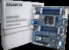
MP30-AR1 Quick Reference Guide 12 3 4 5 67 30 29 31 33 28 32 27 35 26 36 8 9 back plane board header Case open intrusion alert header IPMB connector System fan connector#4 SATA port 3 DOM support jumper SATA 3 6Gb/s connector SATA 3 6Gb/s connector SATA 3 6Gb/s connector SATA 3 6Gb/s
-
 1
1
 |
 |
MP30-AR1 Quick Reference Guide/
快速测试参考指南
No.
Code
Descrip°on
1
LED_STA
System status LED
2
USB2_MLAN
KVM Server Management 10/100/1000 LAN port (top)/USB 2.0 ports (bo±om)
3
VGA1_COM1
Serial port (top)/VGA port (bo±om)
4
SFP+_1_2
SFP+ LAN port #1/#2
5
LAN1_2
GbE LAN port #1/#2
6
SW_PWR
Power bu±on with LED
7
SW_ID
ID switch bu±on with LED
8
CPU_FAN
CPU fan connector
9
DIMM_P0_A0
Channel 1 slot 0
10
DIMM_P0_A1
Channel 1 slot 1
11
DIMM_P0_B0
Channel 2 slot 0
12
DIMM_P0_B1
Channel 2 slot 1
13
CPU0
AppliedMicro® X-Gene 1 processor
14
P12V_AUX
14 pin power connector
15
ATX1
24 pin main power connector
16
SYS_FAN1
System fan connector#1
17
FP_1
Front panel header (for Server system)
18
SYS_FAN2
System fan connector#2
19
PMBUS
PMBus header
20
CLR_CMOS
Clear CMOS jumper
No.
Code
Descrip°on
21
SYS_FAN3
System fan connector#3
22
BP_1
HDD back plane board header
23
CASE_OPEN
Case open intrusion alert header
24
IPMB
IPMB connector
25
SYS_FAN4
System fan connector#4
26
SATA_DOM0
SATA port 3 DOM support jumper
27
SATA0
SATA 3 6Gb/s connector
28
SATA1
SATA 3 6Gb/s connector
29
SATA2
SATA 3 6Gb/s connector
30
SATA3
SATA 3 6Gb/s connector
31
PCIE_2
PCI Express x16 slot
32
BAT
Ba±ery socket
33
PCIE_1
PCI Express x16 slot
34
LED_BMC
BMC firmwar readiness LED
35
DIMM_P0_C0
Channel 3 slot 0
36
DIMM_P0_C1
Channel 3 slot 1
37
DIMM_P0_D0
Channel 4 slot 0
38
DIMM_P0_D1
Channel 4 slot 1
1
2
3
4
5
6
7
8
9
12
13
14
15
16
17
18
19
20
21
22
23
24
25
26
28
29
30
27
31
32
33
34
35
36
37
38
11
10
2
1
Front Panel Header/
前面板
HDD Back Plane Board Header/
硬盤背板排針
1
24
23
2
No.
Pin Define
1
Power LED+
3
No Pin
5
Power LED-
7
HDD LED+
9
HDD LED-
11
Power Bu±on
13
GND
15
Reset Bu±on+
17
GND
19
ID Switch+
21
ID Switch-
23
NMI Switch-
No.
Pin Define
2
5V Standby
4
ID LED+
6
ID LED-
8
System Status LED+
10
System Status LED-
12
LAN1 Ac°ve LED+
14
LAN1 Link LED-
16
SMBus Data
18
SMBus Clock
20
Case Open
22
LAN2 Ac°ve LED
24
LAN2 Link LED-
12
25 26
No.
Pin Define
1
BP_SGP_CLK
3
BP_SGP_LD
5
BP_SGP_DOUT
7
Key Pin
9
GND
11
BP_LED_G_N
13
BP_SGP_DIN
15
GND
17
GND
19
P_3V3_AUX
21
P_3V3_AUX
23
GND
25
BP_PRESENSE
No.
Pin Define
2
No Connect
4
FAN_Gate
6
GND
8
Reset
10
BP_LED_A_N
12
GND
14
No Connect
16
SMB_BP_DATA
18
SMB_BP_CLK
20
BMC_ACK
22
BMC_REQ
24
Key Pin
26
GND
ATX Power/
电源
No.
Pin Define
1
3.3V
2
3.3V
3
GND
4
+5V
5
GND
6
+5V
7
GND
8
Power Good
9
5VSB
10
+12V
11
+12V
12
3.3V
No.
Pin Define
1
GND
2
GND
No.
Pin Define
13
3.3V
14
-12V
15
GND
16
PS_ON
17
GND
18
GND
19
GND
20
-5V
21
+5V
22
+5V
23
+5V
24
GND
2
1
4
3
No.
Pin Define
3
+12V
4
+12V
1
13
12
24
1
5
No
Pin Define
1
SMB CLK
2
SMB DATA
3
SMB ALERT
PMBUS
No
Pin Define
4
GND
5
3.3V SENSE
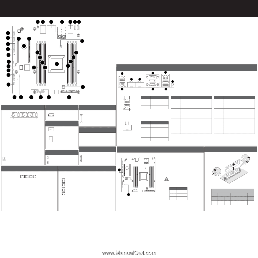
Memory Popula°on Configura°on/
安装内存
1 Slot
1DPC
1DPC
2DPC
A0 or C0
8 Slot
2DPC
Inser Full
A0+B0
or
A0+C0
1DPC
A0+B0
and
C0+D0
2DPC
A0+A1+B0+B1
or
A0+A1+C0+D0
A0+A1
or
C0+C1
2 Slot
4 Slot
Slot Per Channel (SPC) and DIMM Per Channel (DPC)
Rear I/O Connector
/
后面板接口
Off
State
Description
Yellow On
1Gbps data arte
Green On
100Mbps data arte
10Mbps data arte
10/100/1000 LAN LED:
State
Description
Green On
Green Blink
Yellow On
Yellow Blink
Off
10 Gbps data rate
Identify 10 Gbps data rate
1 Gbps data rate
Identify 1 Gbps data rate
100 Mbps data rate
SFP+ LAN LED:
State
Description
Green On
System is operating normally.
Green Blink
Degrade condition, may indicates the following:
CPU failure
DIMM killed
Amber On
Critical condition, may indicates the following:
Power module failure
System fan failure
Power supply voltage issue
System temperature/voltage issue
Amber Blink
Non-critical condition, may indicates the following:
Redundant power module failure
Temperature and voltage issue
Chassis intrusion
N/A
System is not ready. May indicate the following:
POST error
NMI error
Processor or terminator missing
System Status LED:
Speed LED
Link/Ac°vity
LED
Speed LED
Link/Ac°vity
LED
Speed LED
Link/Ac°vity
LED
No.
Desrip°on
1
GbE LAN ports
2
SFP+ LAN ports
3
Serial port
4
VGA port
5
KVM Server Management 10/100/1000 LAN port (Dedicated LAN port)
6
USB 2.0 ports
7
System Status LED
系统状态LED:
绿色恒亮
绿色闪烁
橙色恒亮
橙色闪烁
颜色/状态
说明
系统正常运行
。
无亮灯
效能降低情形,可能为下列状况:
处理器问题
内存问题
严重情形,可能为下列状况:
电源模块故障
系统风扇故障
电源电压问题
系统温度/电压问题
非严重情形,可能为下列状况:
冗余电源模块故障
系统温度/电压问题
机箱侵入
系统未正常运行,可能为下列状况:
POST错误
NMI错误
处理器或终结器缺失
SATA Connector/SATA
接口
No.
Pin Define
1
GND
2
TXP
3
TXN
4
GND
7
1
No.
Pin Define
5
RXN
6
RXP
7
GND
BMC Firmware Readiness LED
State
Descrip°on
On
BMC firmware is ini°al
Blink
BMC
firmware is ready
Off
AC loss
BMC Firmware Readiness LED (LED_BMC):
CPU/System FAN/
风扇
1
4
4
1
No.
Pin Define
1
GND
2
+12V
3
Sense
4
Speed Control
IPMB
No.
Pin Define
1
Clock
2
GND
3
Data
3
1
Jumper Se±ngs/
跳线设置
No.
Desrip°on
1
Clear CMOS Jumper
1-2 Close: Normal opera°on (Default se²ng)
2-3 Close: Clear CMOS data.
2
SATA Port 3 DOM Support Jumper Jumper
1-2 Close: Enable SATA port DOM support fun°on.
2-3 Close: Normal Opera°on. (Default se²ng)
If a SATA type hard drive is connected to the
motherboard, please ensure the jumper is
closed and set to 2-3 pins (Default se²ng),
in order to reduce any risk of hard disk
damage.
1
2
Definition
P5V
SATA3 Pin7
3
GND
Pin No.
Open: Normal opera°on.
Closed: Ac°ve chassis intrus°on alert.
Chassis Intrusion Alert Header
1
1
2
2
3
4
7
6
5
PN