Gigabyte MSH87DI Manual
Gigabyte MSH87DI Manual
 |
View all Gigabyte MSH87DI manuals
Add to My Manuals
Save this manual to your list of manuals |
Gigabyte MSH87DI manual content summary:
- Gigabyte MSH87DI | Manual - Page 1
MSH87DI-SI LGA1155 socket motherboard for Intel® Core™ i3 / Core™ i5 Core™ i7 processors/ Intel® Pentium® series processors User's Manual Rev. 1001 - Gigabyte MSH87DI | Manual - Page 2
Copyright © 2014 GIGA-BYTE TECHNOLOGY CO., LTD. All rights reserved. The trademarks mentioned in this manual are legally registered to their respective owners. Disclaimer Information in this manual is protected by copyright laws and is the property of GIGABYTE. Changes to the specifications and - Gigabyte MSH87DI | Manual - Page 3
Table of Contents Box Contents...4 MSH87DI-SI Motherboard Layout 5 Chapter 1 Hardware Installation 8 1-1 Installation Precautions 8 1-2 Configuration 37 2-2-3 Intel (R) Rapid Start Technology 38 2-2-4 H/W Monitor...39 2-2-5 Intel(R) Smart Connect Technology 40 2-2-6 Intel(R) Thunderbolt 41 2-3 - Gigabyte MSH87DI | Manual - Page 4
Box Contents Motherboard Driver CD Two SATA cables I/O Shield • The box contents above are for reference only and the actual items shall depend on the product package you obtain. The box contents are subject to change without notice. • The motherboard image is for reference only. - 4 - - Gigabyte MSH87DI | Manual - Page 5
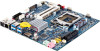
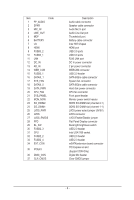
MSH87DI-SI Motherboard Layout 1 2 3 4 5 6 7 8 9 10 11 12 13 37 14 36 35 16 15 17 34 18 24 23 19 20 25 21 22 33 32 31 30 29 28 27 26 - 5 - - Gigabyte MSH87DI | Manual - Page 6
Flat Panel Display connector Back light brightness switch USB 2.0 header Intel LGA1155 socket USB 2.0 header USB 2.0 header mSATA/extension board connector PCI Express x4 slot (Support 25W Only) Digital Mic header Clear CMOS jumper - 6 - - Gigabyte MSH87DI | Manual - Page 7
, carefully read the user's manual and follow these procedures: • Prior to installation, do not remove or break motherboard S/N (Serial Number) sticker or you are uncertain about any installation steps or have a problem related to the use of the product, please consult a certified computer technician. - Gigabyte MSH87DI | Manual - Page 8
L3 cache varies with CPU ŠŠ Intel® H87 Controller Hub ŠŠ 2 x 1.5V DDR3 SO-DIMM slot ŠŠ Max. to 16GB (8GB x 2) ŠŠ Dual channel architecture ŠŠ Support for DDR3 1333/1600 MHz ŠŠ 1 x HDMI 1.4a out ŠŠ 1 x DP 1.2 (Thunderbolt port) ŠŠ 1 x LVDS slot (Max. Resolution: 1920x1080x60) ŠŠ Realtek ALC887 codec - Gigabyte MSH87DI | Manual - Page 9
Back Panel Connectors I/O Controller Hardware Monitor BIOS Form Factor ŠŠ 1 x DC-IN ŠŠ 1 x RJ-45 port ŠŠ 1 x HDMI port ŠŠ 1 x Thunderbolt port ŠŠ 4 x USB 3.0 ports ŠŠ 1 x Audio MIC In ŠŠ 1 x Audio Line Out ŠŠ iTE IT8773 chip ŠŠ CPU/System temperature detection ŠŠ CPU fan speed detection ŠŠ 1 x 64 - Gigabyte MSH87DI | Manual - Page 10
1-3 Installing the CPU and CPU Cooler Read the following guidelines before you begin to install the CPU: • Make sure that the motherboard supports the CPU. • Always turn off the computer and unplug the power cord from the power outlet before installing the CPU to prevent hardware damage. • Locate - Gigabyte MSH87DI | Manual - Page 11
B. Follow the steps below to correctly install the CPU into the motherboard CPU socket. Before installing the CPU, make sure to turn off the computer and unplug the power cord from the power outlet power plug to - Gigabyte MSH87DI | Manual - Page 12
that the Male and Female push pins are joined closely. (Refer to your CPU cooler installation manual for instructions on installing the cooler.) Step 5: After the installation, check the back of the motherboard. If the push pin is inserted as the picture above shows, the installation is complete - Gigabyte MSH87DI | Manual - Page 13
. If you are unable to insert the memory, switch the direction. 1-4-1 Dual Channel Memory Configuration This motherboard provides two DDR3 memory sockets and supports Dual Channel Technology. After the memory is installed, the BIOS will automatically detect the specifications and capacity of the - Gigabyte MSH87DI | Manual - Page 14
computer and unplug the power cord from the power outlet to prevent damage to the memory module. Be sure to install DDR3 DIMMs on this motherboard. Installation Step: Step 1. Align the memory with the DIMM module and insert the DIMM memory module into the DIMM slot. Please note that memory module - Gigabyte MSH87DI | Manual - Page 15
/video signals and is HDCP compliant. Connect the HDMI audio/video device to this port. The HDMI Technology can support a maximum resolution of 1920x1080p but the actual resolutions supported depend on the monitor being used. • When After installing the HDMI device, make sure the default device - Gigabyte MSH87DI | Manual - Page 16
is occurring • When removing the cable connected to a back panel connector, first remove the cable from your device and then remove it from the motherboard. • When removing the cable, pull it straight out from the connector. Do not rock it side to side to prevent an electrical short inside - Gigabyte MSH87DI | Manual - Page 17
devices. • After installing the device and before turning on the computer, make sure the device cable has been securely attached to the connector on the motherboard. Hardware Installation - 18 - - Gigabyte MSH87DI | Manual - Page 18
1) SYS_PANEL (Front Panel Header) Connect the power switch, reset switch, speaker, chassis intrusion switch/sensor and system status indicator on the chassis to this header according to the pin assignments below. Note the positive and negative pins before connecting the cables. 12 9 10 Pin No. 1 2 - Gigabyte MSH87DI | Manual - Page 19
(SATA 6Gb/s Connectors) The SATA connectors conform to SATA 6Gb/s standard and are compatible with SATA 3Gb/s standard. Each SATA connector supports a single SATA device. SATAIII_0 SATAIII_1 7 Pin No. Definition 1 GND 2 TXP 3 TXN 4 GND 1 5 RXN 6 RXP 7 GND Hardware Installation - 20 - Gigabyte MSH87DI | Manual - Page 20
5) FUSB2_3 (USB 2.0 Header) The headers conform to USB 2.0 specification. Each USB header can provide two USB ports via an optional USB bracket. For purchasing the optional USB bracket, please contact the local dealer. 2 10 1 9 Pin No. 1 2 3 4 5 6 7 8 9 10 Definition VCC VCC USBUSBUSB+ USB+ - Gigabyte MSH87DI | Manual - Page 21
8) FUSB3_1 (USB 3.0 Header) The headers conform to USB 3.0 specification. Each USB header can provide two USB ports via an optional USB bracket. For purchasing the optional USB bracket, please contact the local dealer. Pin No. Definition 1 Power 1011 2 IntA_P1_SSRX- 3 IntA_P1_SSRX+ 4 GND 5 - Gigabyte MSH87DI | Manual - Page 22
design. When connecting a fan cable, be sure to connect it in the correct orientation (the black connector wire is the ground wire). The motherboard supports CPU fan speed control, which requires the use of a CPU fan with fan speed control design. For optimum heat dissipation, it is recommended - Gigabyte MSH87DI | Manual - Page 23
) The front panel audio header supports Intel High Definition audio (HD) and AC'97 audio. You may connect your chassis front panel audio module to this header. Make sure the wire assignments of the module connector match the pin assignments of the motherboard header. Incorrect connection between the - Gigabyte MSH87DI | Manual - Page 24
15) FPD (Flat Panel Display Header) Flat Panel Display (FPD)is a high-speed interface connecting the output of a video controller in a laptop computer, computer monitor or LCD television set to the display panel. Most laptops, LCD computer monitors and LCD TVs use this interface internally. The - Gigabyte MSH87DI | Manual - Page 25
17) LVDS (LVDS Header) LVDS stands for Low-voltage differential signaling, which uses high-speed analog circuit techniques to provide multigigabit data transfers on copper interconnects and is a generic interface standard for high-speed data transmission. 1 40 Pin No. 1 2 3 4 5 6 7 8 9 10 11 12 - Gigabyte MSH87DI | Manual - Page 26
the jumper cap from the jumper. Failure to do so may cause damage to the motherboard. • After system restart, go to BIOS Setup to load factory defaults (select Restore Defaults) or manually configure the BIOS settings (refer to Chapter 2, "BIOS Setup," for BIOS configurations). - 27 - Hardware - Gigabyte MSH87DI | Manual - Page 27
20) LVDS_PWR (LVDS Power Select Jumper) 1 1-2 Close: Set to 3V. 1 2-3 Close: Set to 5V. (Default setting) 21) LVDS_EN/DIS (LVDS Enable/Disable Jumper) 1 1-2 Close: Enable LVDS funciton. (Default setting) 1 2-3 Close: Disable LVDS funciton. Hardware Installation - 28 - - Gigabyte MSH87DI | Manual - Page 28
22) BL_SW (Back Light Switch) The Back Light switch provides the function for screen back light adjustment. 1 2 Pin No. 1 2 Definition BL_DOWN BL_UP - 29 - Hardware Installation - Gigabyte MSH87DI | Manual - Page 29
features. When the power is turned off, the battery on the motherboard supplies the necessary power to the CMOS to keep the configuration values turned on. • BIOS flashing is potentially risky, if you do not encounter problems of using the current BIOS version, it is recommended that you don't flash - Gigabyte MSH87DI | Manual - Page 30
Main This setup page includes all the items in standard compatible BIOS Advanced This setup page includes all the items of AMI BIOS special enhanced features. (ex: Auto detect fan and temperature status, automatically configure hard disk parameters.) Chipset Northbridge and Southbridge - Gigabyte MSH87DI | Manual - Page 31
2-1 The Main Menu Once you enter the BIOS Setup program, the Main Menu (as shown below) appears on the screen. Use arrow keys to move among the items and press to accept or enter other sub-menu. Main Menu Help The on-screen description of a highlighted setup option is displayed on the bottom - Gigabyte MSH87DI | Manual - Page 32
BIOS Information Project Name Display name of the project. BIOS Version Display version number of the BIOS. BIOS Build Date and Time Displays the date and time when the BIOS setup utility was created. LAN MAC Address Displays the MAC address information. Memory Information Size Determines how much - Gigabyte MSH87DI | Manual - Page 33
2-2 Advanced Menu The Advanced menu display submenu options for configuring the function of various hardware components. Select a submenu item, then press Enter to access the related submenu screen. BIOS Setup - 34 - - Gigabyte MSH87DI | Manual - Page 34
CPU Type/Signature/Microcode Patch/CPU Speed/Processor Cores/ Intel HT Technology/Intel VT-x Technology/Intel SMX Technology Displays the technical specifications for the installed processor. 64-bit Display the supported infprmation of installed CPU. Cache Information L1 Data Cache / L1 Code - Gigabyte MSH87DI | Manual - Page 35
C3) report. Options available: Disabled/CPU C7/CPU C7s. Default setting is CPU C7s. (Note) This item is present only if you install a CPU that supports this feature. For more information about Intel CPUs' unique features, please visit Intel - Gigabyte MSH87DI | Manual - Page 36
be labeled on the outside device casing. Enter the appropriate option based on this information. Hot Plug (for Serial SATA Port 0/1) Enable/Disable Hot Plug support for Serial ATA Port 0/1. Options available: Enabled/Disabled. Default setting is Disabled. - 37 - BIOS Setup - Gigabyte MSH87DI | Manual - Page 37
Intel (R) Rapid Start Technology Intel (R) Rapid Start Technology Enable/Disable the Intel Rapid Start Technology (IRSTe) funciton. The . Default setting is 10 minutes. Active Page Threshold Support If enabled, the system will support RST with small partition. Option available: Enabled/Disabled. - Gigabyte MSH87DI | Manual - Page 38
2-2-4 H/W Monitor Press Enter to view the Hardware Monitor screen which displays a real-time record of the CPU/system temperature, and fan speed, The related system voltage and temperature items on this window are nonconfigurable. CPU/System FAN Fail Detect Enable CPU/System Fan Stop Warning - Gigabyte MSH87DI | Manual - Page 39
2-2-5 Intel(R) Smart Connect Technology Intel(R) Smart Connect Technology Enable/Disable Intel(R) Smart Connect Technology function. Option available: Enabled/Disabled. Default setting is Disabled. BIOS Setup - 40 - - Gigabyte MSH87DI | Manual - Page 40
Intel(R) Thunderbolt Intel(R) Thunderbolt Technology Thunderbolt Specification Version Display Thunderbolt Thunderbolt Devices Option available: Enabled/Disabled. Default setting is Enabled. AIC Support Option available: Enabled/Disabled. Default setting is Disabled. Thunderbolt PCIe Cache - Gigabyte MSH87DI | Manual - Page 41
Notify Support Option available: Enabled/Disabled. Default setting is Enabled. Thunderbolt Surprise-Removal Option available: / keys to increase or decrease the desired values. TBT Device ID resource Support Option available: Enabled/Disabled. Default setting is Disabled. BIOS Setup - 42 - - Gigabyte MSH87DI | Manual - Page 42
Menu Onboard Audio Device Enable/Disable onboard audio controller. Options available: Enabled/Disabled. Default setting is Enabled. DMIC Support Enable/Disable DMIC Support function . Options available: Enabled/Disabled. Default setting is Disabled. Restore AC Power Loss This option provides user - Gigabyte MSH87DI | Manual - Page 43
XHCI Mode Configure XHCI (USB2.0) Mode. Options available: Auto/Disabled. Default setting is Auto. Intel ME FW Update Enable/Disable Intel ME firmware update. Options available: Enabled/Disabled. Default setting is Disabled. Please note that when the ME is locked, you need to enable this item for ME - Gigabyte MSH87DI | Manual - Page 44
2-4 Boot Menu The Boot menu allows you to set the drive priority during system boot-up. BIOS setup will display an error message if the drive(s) specified is not bootable. Boot Configuration Boot Option Priorities Boot Option #1 Press Enter to configure the boot priority. CSM parameters Press Enter - Gigabyte MSH87DI | Manual - Page 45
when the Launch CSM is set to Enabled. • If the Launch CSM is set to Disabled, the following five items will not be able to support Legacy mode. Boot option filter Determines which devices system will boot to. Options available: UEFI and Legacy/Legacy only/UEFI only. Default setting is UEFI - Gigabyte MSH87DI | Manual - Page 46
Network stack Enable/Disable UEFI network stack. Options available: Enabled/DIsabled. Default setting is Disabled. - 47 - BIOS Setup - Gigabyte MSH87DI | Manual - Page 47
2-5 Security Menu The Security menu allows you to safeguard and protect the system from unauthorized use by setting up access passwords. There are two types of passwords that you can set: • Adminstrator Password Entering this password will allow the user to access and change all settings in the - Gigabyte MSH87DI | Manual - Page 48
Secure Boot Mode Define the Secure Boot Mode. Option available: Standard/Custom. Default setting is Standard. Key Management(Note) Press [Enter] for configuration of advanced items. (Note) Advanced items prompt when this item is set to Cutom. - 49 - BIOS Setup - Gigabyte MSH87DI | Manual - Page 49
2-5-1 Key Management Key Management This item appears only when the Secure Boot Mode is set to Custom. Default Key Provisioning Force the system to Setup Mode. This will clear all Secure Boot Variables such as Platform Key (PK), Key-exchange Key (KEK), Authorized Signature Database (db), and - Gigabyte MSH87DI | Manual - Page 50
Set new KEK Press [Enter] to configure a new KEK. Append Var to KEK Press [Enter] to load additional KEK from a storage devices for an additional db and dbx management. Authorized Signature Database (DB) Display the status of Authorized Signature Database. Delete DB Press [Enter] to delete the db - Gigabyte MSH87DI | Manual - Page 51
2-6 Exit Menu The Exit menu displays the various options to quit from the BIOS setup. Highlight any of the exit options then press Enter. Save Changes and Reset Saves changes made and close the BIOS setup and reset the system. Options available: Yes/No. Discard Changes and Reset Discards changes
-
 1
1 -
 2
2 -
 3
3 -
 4
4 -
 5
5 -
 6
6 -
 7
7 -
8
-
9
-
10
-
11
-
12
-
13
-
14
-
15
-
16
-
17
-
18
-
19
-
20
-
21
-
22
-
23
-
24
-
25
-
26
-
27
-
28
-
29
-
30
-
31
-
32
-
33
-
34
-
35
-
36
-
37
-
38
-
39
-
40
-
41
-
42
-
43
-
44
-
45
-
46
-
47
-
48
-
49
-
50
-
51
 |
 |

MSH87DI-SI
LGA1155 socket motherboard for Intel
®
Core
™
i3 / Core
™
i5
Core
™
i7 processors/ Intel
®
Pentium
®
series processors
User's Manual
Rev. 1001