Gigabyte P55-UD3L User Manual
Gigabyte P55-UD3L Manual
 |
View all Gigabyte P55-UD3L manuals
Add to My Manuals
Save this manual to your list of manuals |
Gigabyte P55-UD3L manual content summary:
- Gigabyte P55-UD3L | User Manual - Page 1
GA-P55-UD3L-TPM GA-P55-UD3L GA-P55-US3L LGA1156 socket motherboard for Intel® Core™ i7 processor family/ Intel® Core™ i5 processor family/Intel® Core™ i3 processor family User's Manual Rev. 2301 12ME-P55UD3L-2301R - Gigabyte P55-UD3L | User Manual - Page 2
Motherboard GA-P55-UD3L-TPM/GA-P55-UD3L/GA-P55-US3L May 20, 2010 Motherboard GA-P55-UD3L-TPM / GA-P55-UD3L /GA-P55-US3L May 20, 2010 - Gigabyte P55-UD3L | User Manual - Page 3
the product. For detailed product information, carefully read the User's Manual. For instructions on how to use GIGABYTE's unique features, read or download the information on/from the Support&Downloads\Motherboard\Technology Guide page on our website. For product-related information, check on our - Gigabyte P55-UD3L | User Manual - Page 4
GA-P55-UD3L-TPM/GA-P55-UD3L/GA-P55-US3L Motherboard Layout 7 GA-P55-UD3L-TPM/GA-P55-UD3L/GA-P55-US3L Motherboard Block Diagram...........8 Chapter 1 Hardware Installation 9 1-1 Installation Precautions 9 1-2 Product Specifications 10 1-3 Installing the CPU and CPU 2-5 Advanced BIOS Features 46 - Gigabyte P55-UD3L | User Manual - Page 5
Channel Audio 92 5-2-2 Configuring S/PDIF In/Out 95 5-2-3 Configuring Microphone Recording 97 5-2-4 Using the Sound Recorder 99 5-3 Troubleshooting 100 5-3-1 Frequently Asked Questions 100 5-3-2 Troubleshooting Procedure 101 5-4 Regulatory Statements 103 j Only for GA-P55-UD3L-TPM - Gigabyte P55-UD3L | User Manual - Page 6
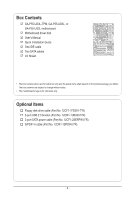
Box Contents GA-P55-UD3L-TPM, GA-P55-UD3L, or GA-P55-US3L motherboard Motherboard driver disk User's Manual Quick Installation Guide One without notice. • The motherboard image is for reference only. Optional Items Floppy disk drive cable (Part No. 12CF1-1FD001-7*R) 2-port USB 2.0 bracket (Part - Gigabyte P55-UD3L | User Manual - Page 7
GA-P55-UD3L-TPM/GA-P55-UD3L/GA-P55-US3L Motherboard Layout KB_USB ATX_12V GA-P55-UD3L-TPM/ GA-P55-UD3L / GA-P55-US3L PHASE LED LGA1156 PWR_FAN COAXIAL COMA LPT R_USB ATX USB_LAN AUDIO F_AUDIO SYS_FAN1 PCIEX1 (Note 1) BAT CPU_FAN DDR3_2 DDR3_1 DDR3_4 DDR3_3 Realtek RTL8111E CODEC - Gigabyte P55-UD3L | User Manual - Page 8
GA-P55-UD3L-TPM/GA-P55-UD3L/GA-P55-US3L Motherboard Block Diagram PCIe CLK (100 MHz) 1 PCI Express x16 LGA1156 CPU CPU CLK+/- ( Dual BIOS 6 SATA 3Gb/s 2 SATA 3Gb/s ATA-133/100/66/33 IDE Channel PCI Bus GIGABYTE SATA2 CODEC 12 USB Ports LPC Bus iTE IT8720 Floppy COM Port PS/2 KB/Mouse TPM j - Gigabyte P55-UD3L | User Manual - Page 9
's manual and follow these procedures: • Prior to installation, do not remove or break motherboard S/N wrist strap when handling electronic com- ponents such as a motherboard, CPU or memory. If you do not have an ESD wrist steps or have a problem related to the use of the product, please consult - Gigabyte P55-UD3L | User Manual - Page 10
1-2 Product Specifications CPU Support for an Intel® Core™ i7 series processor/Intel® Core™ i5 series processor /Intel® Core™ i3 series processor in the LGA1156 package (Go to GIGABYTE's website for the latest CPU support list.) L3 cache varies with CPU Chipset Intel® H55 Express Chipset - Gigabyte P55-UD3L | User Manual - Page 11
w 8 x USB 2.0/1.1 ports w 1 x RJ-45 port w 3 x audio jacks (Line In/Line Out/Microphone) I/O Controller w iTE IT8720 chip Hardware Monitor w w w w w w BIOS w w w w System voltage detection CPU/System temperature detection CPU/System - Gigabyte P55-UD3L | User Manual - Page 12
™ 2 Support for Smart TPM j Support for Smart 6™ Support for Auto Green Support for ON/OFF Charge Support for Q-Share Norton Internet Security (OEM version) Operating System w Support for Microsoft® Windows® 7/Vista/XP Form Factor w ATX Form Factor; 30.5cm x 19.0cm j Only for GA-P55-UD3L-TPM - Gigabyte P55-UD3L | User Manual - Page 13
before you begin to install the CPU: • Make sure that the motherboard supports the CPU. (Go to GIGABYTE's website for the latest CPU support list.) • Always turn off the computer and unplug the power cord from the power outlet before installing the CPU to prevent hardware damage. • Locate the - Gigabyte P55-UD3L | User Manual - Page 14
B. Follow the steps below to correctly install the CPU into the motherboard CPU socket. Before installing the CPU, make sure to turn off the computer and unplug the power cord from the power outlet to prevent damage to the CPU. Step 1: Gently press the CPU socket lever handle down and away from the - Gigabyte P55-UD3L | User Manual - Page 15
pin. Check that the Male and Female push pins are joined closely. (Refer to your CPU cooler installation manual for instructions on installing the cooler.) Step 5: After the installation, check the back of the motherboard. If the push pin is inserted as the picture above shows, the installation is - Gigabyte P55-UD3L | User Manual - Page 16
motherboard provides four DDR3 memory sockets and supports Dual Channel Technology. After the memory is installed, the BIOS will automatically detect the specifications or DDR3_3 sockets. DDR3_2 DDR3_1 DDR3_4 DDR3_3 Due to CPU limitations, read the following guidelines before installing the memory - Gigabyte P55-UD3L | User Manual - Page 17
to the memory module. DDR3 and DDR2 DIMMs are not compatible to each other or DDR DIMMs. Be sure to install DDR3 DIMMs on this motherboard. Notch DDR3 DIMM A DDR3 memory module has a notch, so it can only fit in one direction. Follow the steps below to correctly install your memory - Gigabyte P55-UD3L | User Manual - Page 18
an expansion card: • Make sure the motherboard supports the expansion card. Carefully read the manual that came with your expansion card. • Always If necessary, go to BIOS Setup to make any required BIOS changes for your expansion card(s). 7. Install the driver provided with the expansion card - Gigabyte P55-UD3L | User Manual - Page 19
1-6 Back Panel Connectors USB 2.0/1.1 Port The USB port supports the USB 2.0/1.1 specification. Use this port for USB devices such as a USB keyboard/mouse, USB printer, USB flash drive and etc. PS/2 Keyboard/Mouse Port Use this port to connect a PS/2 keyboard or mouse. Parallel Port Use the - Gigabyte P55-UD3L | User Manual - Page 20
to this jack. To configure 7.1-channel audio, you need connect with the port of HD Audio standard via front panel and enable the multi-channel audio feature through the audio driver. Refer to the instructions on setting up a 2/4/5.1/7.1-channel audio configuration in Chapter 5, "Configuring - Gigabyte P55-UD3L | User Manual - Page 21
devices. • After installing the device and before turning on the computer, make sure the device cable has been securely attached to the connector on the motherboard. - 21 - Hardware Installation - Gigabyte P55-UD3L | User Manual - Page 22
supply can supply enough stable power to all the components on the motherboard. Before connecting the power connector, first make sure the power supply is the correct orientation. The 12V power connector mainly supplies power to the CPU. If the 12V power connector is not connected, the computer will - Gigabyte P55-UD3L | User Manual - Page 23
to connect it in the correct orientation (the black connector wire is the ground wire). The motherboard supports CPU fan speed control, which requires the use of a CPU fan with fan speed control design. For optimum heat dissipation, it is recom- mended that a system fan be installed inside the - Gigabyte P55-UD3L | User Manual - Page 24
, read the instructions from the device manufacturers.) 39 1 40 2 8) SATA2_0/1/2/3/4/5 (SATA 3Gb/s Connectors, Controlled by H55 Chipset ) The SATA connectors conform to SATA 3Gb/s standard and are compatible with SATA 1.5Gb/s standard. Each SATA connector supports - Gigabyte P55-UD3L | User Manual - Page 25
supports a single SATA device. The GIGABYTE SATA2 controller supports RAID 0, RAID 1, and JBOD. Refer to Chapter 5, "Configuring SATA Hard Drive(s)," for instructions BATTERY) The battery provides power to keep the values (such as BIOS configurations, date, and time information) in the CMOS when the - Gigabyte P55-UD3L | User Manual - Page 26
beep will be heard if no problem is detected at system startup. If a problem is detected, the BIOS may issue beeps in different patterns to indicate the problem. Refer to Chapter 5, "Troubleshooting," for information about beep codes. • HD (Hard Drive Activity LED, Blue) Connects to the hard drive - Gigabyte P55-UD3L | User Manual - Page 27
NC • The front panel audio header supports HD audio by default. If your chassis provides an AC'97 front panel audio module, refer to the instructions on how to activate AC'97 functionality via the audio software in Chapter 5, "Configuring 2/4/5.1/7.1-Channel Audio." • Audio signals will be present - Gigabyte P55-UD3L | User Manual - Page 28
Definition 1 Power 1 2 SPDIFI 3 GND 15) SPDIF_O (S/PDIF Out Header) This header supports digital S/PDIF Out and connects a S/PDIF digital audio cable (provided by expansion cards) for digital audio output from your motherboard to certain expansion cards like graphics cards and sound cards. For - Gigabyte P55-UD3L | User Manual - Page 29
the jumper. Failure to do so may cause damage to the motherboard. • After system restart, go to BIOS Setup to load factory defaults (select Load Optimized Defaults) or manually configure the BIOS settings (refer to Chapter 2, "BIOS Setup," for BIOS configurations). - 29 - Hardware Installation - Gigabyte P55-UD3L | User Manual - Page 30
18) PHASE LED The number of lighted LEDs indicates the CPU loading. The higher the CPU loading, the more the number of lighted LEDs. To enable the Phase LED display function, please first enable Dynamic Energy Saver™ 2. Refer to Chapter 4, "Dynamic Energy Saver™ 2," for more details. Hardware - Gigabyte P55-UD3L | User Manual - Page 31
the GIGABYTE Q-Flash or @BIOS utility. • Q-Flash allows the user to quickly and easily upgrade or back up BIOS without entering the operating system. • @BIOS is a Windows-based utility that searches and downloads the latest version of BIOS from the Internet and updates the BIOS. For instructions on - Gigabyte P55-UD3L | User Manual - Page 32
v6.00PG, An Energy Star Ally Copyright (C) 1984-2009, Award Software, Inc. Motherboard Model BIOS Version P55-UD3L E6c . . . . : BIOS Setup : XpressRecovery2 : Boot Menu : Qflash 11/06/2009-P55-7A89TG0AC-00 Function Keys Function Keys Function Keys: : POST SCREEN Press - Gigabyte P55-UD3L | User Manual - Page 33
Save & Exit Setup Change CPU's Clock & Voltage F11: Save CMOS to BIOS F12: Load CMOS from BIOS BIOS Setup Program Function Keys Move • The BIOS Setup menus described in this chapter are for reference only and may differ by BIOS version. j Only for GA-P55-UD3L-TPM. - 33 - BIOS Setup - Gigabyte P55-UD3L | User Manual - Page 34
Abandon all changes and the previous settings remain in effect. Pressing to the confirmation message will exit BIOS Setup. (Pressing can also carry out this task.) Security Chip Configuration j Use this menu to configure the TPM function. j Only for GA-P55-UD3L-TPM. BIOS Setup - 34 - - Gigabyte P55-UD3L | User Manual - Page 35
BIOS Version BCLK CPU overclock/overvoltage settings you made is dependent on your overall system configurations. Incorrectly doing overclock/overvoltage may result in damage to CPU Control CPU Clock Drive PCI Express Clock Drive CPU you install a CPU that supports this feature. For - Gigabyte P55-UD3L | User Manual - Page 36
be reduced during system halt state to decrease power consumption. Auto lets the BIOS automatically configure this setting. (Default: Auto) (Note) This item is present only if you install a CPU that supports this feature. For more information about Intel CPUs' unique features, please visit Intel - Gigabyte P55-UD3L | User Manual - Page 37
is configurable only if the Base Clock(BCLK) Control option is enabled. Important: It is highly recommended that the CPU frequency be set in accordance with the CPU specifications. (Note) This item is present only if you install a CPU that supports this feature. For more information about Intel - Gigabyte P55-UD3L | User Manual - Page 38
BIOS manually set the PCIe clock frequency. The adjustable range is from 90 MHz to 150 MHz. Auto sets the PCIe clock frequency to standard 100 MHz. (Default: Auto) >>>>> Advanced Clock Control CPU , 900mV (default), 1000mV. CPU Clock Skew Allows you to set the CPU clock prior to the Chipset clock - Gigabyte P55-UD3L | User Manual - Page 39
Exit F1: General Help F7: Optimized Defaults Extreme Memory Profile (X.M.P.) (Note) Allows the BIOS to read the SPD data on XMP memory module(s) to enhance memory performance when enabled. This item appears only if you install a memory module that supports this feature. - 39 - BIOS Setup - Gigabyte P55-UD3L | User Manual - Page 40
Control x CAS Latency Time 7 x tRCD 7 x tRP 7 x tRAS 20 >>>>> Channel A Advanced Timing Control Channel A Misc Timing Control x B2B CAS Delay Standard Timing Control CAS Latency Channel A/B Advanced Timing Control tRC Options are: Auto CPU that supports this feature. For - Gigabyte P55-UD3L | User Manual - Page 41
(default), 1~255. tRTP Options are: Auto (default), 1~15. tFAW Options are: Auto (default), 1~63. Command Rate(CMD) Options are: Auto (default), 1~3. >>>>> Channel A/B Misc Timing Control B2B CAS Delay Options are: Auto (default), 1~31. Round Trip Latency Options are: Auto (default), 1~255. - 41 - Gigabyte P55-UD3L | User Manual - Page 42
****** Mother Board Voltage Control ****** Voltage Types Normal Current >>> CPU Load-Line Calibration [Auto] CPU Vcore 1.26875V [Auto] , keeping the CPU voltage more constant under light and heavy CPU load. Disabled sets the CPU voltage following Intel specifications. (Default: - Gigabyte P55-UD3L | User Manual - Page 43
Help F7: Optimized Defaults Isochronous Support Determines whether to enable specific streams within the CPU and Chipset. (Default: Press Enter] [Press Enter] Item Help Menu Level BIOS Version BCLK CPU Frequency Memory Frequency Total Memory Size E5c 133.27 MHz 3198 - Gigabyte P55-UD3L | User Manual - Page 44
of the IDE/SATA device on this channel. IDE Channel 0, 1 Master/Slave Configure your IDE/SATA devices by using one of the three methods below: BIOS Setup - 44 - - Gigabyte P55-UD3L | User Manual - Page 45
Lets the BIOS automatically detect IDE/SATA devices during the POST. (Default) • None If no IDE/SATA devices are used, set this item to None so the system will skip the detection of the device during the POST for faster system startup. • Manual Allows you to manually enter the - Gigabyte P55-UD3L | User Manual - Page 46
hard drive and to issue warnings when a third party hardware monitor utility is installed. (Default: Disabled) (Note) This item is present only if you install a CPU that supports this feature. For more information about Intel CPUs' unique features, please visit Intel's website - Gigabyte P55-UD3L | User Manual - Page 47
GIGABYTE Logo at system startup. Disabled displays normal POST message. (Default: Enabled) Backup BIOS Image to HDD Allows the system to copy the BIOS image file to the hard drive. If the system BIOS only if you install a CPU that supports this feature. For more information about Intel CPUs' unique features, - Gigabyte P55-UD3L | User Manual - Page 48
in the Intel H55 Chipset to AHCI mode. IDE Configures the SATA controller to IDE mode. (Default) AHCI Configures the SATA controller to AHCI mode. Advanced Host Controller Interface (AHCI) is an interface specification that allows the storage driver to enable advanced Serial ATA - Gigabyte P55-UD3L | User Manual - Page 49
audio card instead of using the onboard audio, corresponding LAN controller will be Defaults This motherboard incorporates cable is attached to the motherboard, the Status fields of Normally... If no cable problem is detected on the LAN Windows mode or when the LAN Boot ROM is activated. - 49 - Gigabyte P55-UD3L | User Manual - Page 50
SATA controller to AHCI mode. IDE Disables RAID for the SATA controller and configures the SATA controller to IDE mode. (Default) AHCI Configures the SATA controller to AHCI mode. Advanced Host Controller Interface (AHCI) is an interface specification that allows the storage driver to - Gigabyte P55-UD3L | User Manual - Page 51
On By Mouse Power On By Keyboard x KB Power ON Password AC Back Function ErP Support [S3(STR)] [Instant-Off] [Enabled] [Enabled] [Disabled] Everyday 0 : that supports wake-up function. (Default: Enabled) (Note) Supported on Windows 7/Vista operating system only. - 51 - BIOS Setup - Gigabyte P55-UD3L | User Manual - Page 52
the date and time as following: Date (of Month) Alarm: Turn on the system at a specific time on each day or on a specific day in a month. Time (hh: mm: ss) Alarm: Set the time at which the on by keyboard, and wake on LAN. (Note) Supported on Windows 7/Vista operating system only. BIOS Setup - 52 - - Gigabyte P55-UD3L | User Manual - Page 53
to the motherboard CI header. CPU fan speed control function. Enabled allows the CPU fan to run at different speed according to the CPU temperature. You can adjust the fan speed with EasyTune based on system requirements. If disabled, the CPU fan runs at full speed. (Default: Enabled) - 53 - BIOS - Gigabyte P55-UD3L | User Manual - Page 54
Mode Specifies how to control CPU fan speed. This item is configurable only if CPU Smart FAN Control is set to Enabled. Auto Lets the BIOS automatically detect the type of CPU fan installed and sets the optimal CPU fan control mode. (Default) Voltage Sets Voltage mode for a 3-pin CPU fan. PWM - Gigabyte P55-UD3L | User Manual - Page 55
safest and most stable BIOS settings for the motherboard. 2-10 Load BIOS default settings. The BIOS defaults settings help the system to operate in optimum state. Always load the Optimized defaults after updating the BIOS or after clearing the CMOS values. j Only for GA-P55-UD3L-TPM. - 55 - BIOS - Gigabyte P55-UD3L | User Manual - Page 56
view the BIOS settings but not to make changes. To clear the password, press on the password item and when requested for the password, press again. The message "PASSWORD DISABLED" will appear, indicating the password has been cancelled. j Only for GA-P55-UD3L-TPM. BIOS Setup - 56 - Gigabyte P55-UD3L | User Manual - Page 57
all Data F11: Save CMOS to BIOS F12: Load CMOS from BIOS Press on this item and press the key. This exits the BIOS Setup without saving the changes made in BIOS Setup to the CMOS. Press or to return to the BIOS Setup Main Menu. j Only for GA-P55-UD3L-TPM. - 57 - BIOS Setup - Gigabyte P55-UD3L | User Manual - Page 58
chip and initializes the Security Platform. Disabled Disables the security chip. (Default) Security Chip State Displays the current settings in the security chip. j Only for GA-P55-UD3L-TPM. BIOS Setup - 58 - - Gigabyte P55-UD3L | User Manual - Page 59
install new GIGABYTE utilities. Click Yes to automatically install the utilities. Or click No if you want to manually select the utilities to install on the Application Software page later. • For USB 2.0 driver support under the Windows XP operating system, please install the Windows XP Service Pack - Gigabyte P55-UD3L | User Manual - Page 60
applications that GIGABYTE develops and some free software. You can click the Install button on the right of an item to install it. 3-3 Technical Manuals This page provides GIGABYTE's application guides, content descriptions for this driver disk, and the motherboard manuals. Drivers Installation - Gigabyte P55-UD3L | User Manual - Page 61
3-4 Contact For the detailed contact information of the GIGABYTE Taiwan headquarter or worldwide branch offices, click the URL on this page to link to the GIGABYTE website. 3-5 System This page provides the basic system information. - 61 - Drivers Installation - Gigabyte P55-UD3L | User Manual - Page 62
Center To update the BIOS, drivers, or applications, click the Download Center button to link to the GIGABYTE website. The latest version of the BIOS, drivers, or applications will be displayed. 3-7 New Utilities This page provides a quick link to GIGABYTE's lately developed utilities for users - Gigabyte P55-UD3L | User Manual - Page 63
your system soon after the operating system and drivers are installed. • The amount of data and hard USB hard drives are not supported. • Hard drives in RAID/AHCI mode are not supported. Installation and Configuration: Turn on your system to boot from the Windows Vista setup disk. A. Installing Windows - Gigabyte P55-UD3L | User Manual - Page 64
note that if there is no enough unallocated space, Xpress Recovery2 cannot save the backup file. B. Accessing Xpress Recovery2 1. Boot from the motherboard driver disk to access Xpress Recovery2 for the first time. When you see the following message: Press any key to startup Xpress Recovery2, press - Gigabyte P55-UD3L | User Manual - Page 65
D. Using the Restore Function in Xpress Recovery2 Select RESTORE to restore the backup to your hard drive in case the system breaks down. The RESTORE option will not be present if no backup is created before. E. Removing the Backup Step 1: If you wish to remove the backup file, select REMOVE. Step - Gigabyte P55-UD3L | User Manual - Page 66
However, if the BIOS update file is saved to a hard drive in RAID/AHCI mode or a hard drive attached to an independent IDE/SATA controller, use the key during the POST to access Q-Flash. Award Modular BIOS v6.00PG, An Energy Star Ally Copyright (C) 1984-2009, Award Software, Inc. P55-UD3L E6c - Gigabyte P55-UD3L | User Manual - Page 67
option allows you to save the current BIOS file. • Q-Flash only supports USB flash drive or hard drives using FAT32/16/12 file system. • If the BIOS update file is saved to a hard drive in RAID/AHCI mode or a hard drive attached to an independent IDE/SATA controller, use the key during the - Gigabyte P55-UD3L | User Manual - Page 68
Defaults F11: Save CMOS to BIOS F12: Load CMOS from BIOS Press to load BIOS defaults Step 6: Select Save & Exit Setup and then press to save settings to CMOS and exit BIOS Setup. The procedure is complete after the system restarts. j Only for GA-P55-UD3L-TPM. Unique Features - 68 - - Gigabyte P55-UD3L | User Manual - Page 69
. If the BIOS update file for your motherboard is not present on the @BIOS server site, please manually download the BIOS update file from GIGABYTE's website and follow the instructions in "Update the BIOS without Using the Internet Update Function" below. 2. Update the BIOS without Using the - Gigabyte P55-UD3L | User Manual - Page 70
Available functions in EasyTune 6 may differ by motherboard model. Grayed-out area(s) indicates that the item is not configurable or the function is not supported. Incorrectly doing overclock/overvoltage may result in damage to the hardware components such as CPU, chipset, and memory and reduce the - Gigabyte P55-UD3L | User Manual - Page 71
Interface A. Meter Mode In Meter Mode, GIGABYTE Dynamic Energy Saver™ 2 shows how much Phase LED On/Off Switch (Default: On) 16 Live Utility Update (Check for the latest utility version) • The above data is for reference only. Actual performance may vary depending on motherboard model. • CPU - Gigabyte P55-UD3L | User Manual - Page 72
) 13 INFO/Help 14 Motherboard Phase LED On/Off Switch (Default: On) 15 Live Utility Update (Check for the latest CPU Enhanced Halt (C1E) and CPU EIST Function items in the BIOS Setup program are set to Enabled. (Note 2) 1: Smart FAN/CPU (default); 2: Smart FAN/CPU/VGA/HDD; 3: Smart FAN/CPU - Gigabyte P55-UD3L | User Manual - Page 73
for using Q-Share After installing Q-Share from the motherboard driver disk, go to Start>All Programs>GIGABYTE>Q-Share. exe to launch the Q-Share tool. shared data folder Changes the data folder to be shared (Note) Updates Q-Share online Displays the current Q-Share version Exits Q-Share ( - Gigabyte P55-UD3L | User Manual - Page 74
4-6 Smart 6™ GIGABYTE Smart 6™ (Note 1) is designed with user-friendliness in mind, and Instructions: Select the Enable check box below the BIOS QuickBoot or OS QuickBoot item and then click Save to save the settings. SMART QuickBoost SMART QuickBoost features quick and effortless CPU overclocking - Gigabyte P55-UD3L | User Manual - Page 75
specific backup on PATA and SATA hard drives (partitioned on NTFS file system) in Windows Vista. Instructions click the Copy button. The files/folders listed on the screen are read-only so you BIOS simultaneously, which can prevent loss of the data in case the system/hard drive fails. Instructions - Gigabyte P55-UD3L | User Manual - Page 76
were moved within the hard drive or copied to an external storage device (Note 5). Instructions: Select the Enable check box at the bottom of the ON/OFF Recorder or File the User Password in the system BIOS Setup program to prevent the system time being changed by other users. Unique Features - 76 - Gigabyte P55-UD3L | User Manual - Page 77
to the Bluetooth cell phone or when plugging in the USB flash drive that is configured as the Smart TPM user key. Selecting the Enable Backup to BIOS check box will store the encrypted TPM User Password in the system BIOS. j Only for GA-P55-UD3L-TPM. 3. Click OK to complete the settings. - 77 - Gigabyte P55-UD3L | User Manual - Page 78
your Bluetooth cell phone, click Refresh to let Auto Green re-detect the device.) Before creating a Bluetooth cell phone key, make sure your motherboard has a Bluetooth receiver and you have turned on the search and Bluetooth functions on your phone. Configuring the Bluetooth cell phone key: After - Gigabyte P55-UD3L | User Manual - Page 79
hard drive(s) in your computer. B. Configure SATA controller mode in BIOS Setup. C. Configure a RAID array in RAID BIOS. (Note 1) D. Make a floppy disk containing the SATA RAID/AHCI driver for Windows XP. (Note 2) E. Install the SATA RAID/AHCI driver and operating system. (Note 2) Before you begin - Gigabyte P55-UD3L | User Manual - Page 80
motherboard, the GSATA2_0 and GSATA2_1 ports are supported by the GIGABYTE SATA2 SATA controller. Then connect the power connector from your power supply to the hard drive. B. Configuring SATA controller mode in BIOS Setup Make sure to configure the SATA controller mode correctly in system BIOS - Gigabyte P55-UD3L | User Manual - Page 81
Utility" (Figure 2). Press + to enter the RAID setup utility. GIGABYTE Technology Corp. PCI Express to SATAII HOST Controller ROM v1.07.06 Copyright (C) 2005-2009 Gigabyte Technology Corp. (http://www.gigabyte.com) HDD0 : HDD1 : ST3120026AS ST3120026AS 120 GB 120 GB Non-RAID - Gigabyte P55-UD3L | User Manual - Page 82
characters in length for the created RAID drive to be identified by system BIOS or OS. [fg]-Move Cursor [DEL,BS]-Delete Character Figure 4 [ Stripe Select Disk 128 KB 240 GB Gigabyte Technology Corp. RAID Setup Utility v1.07.06 [ Hard Disk Drive List ] Model Name HDD0: ST3120026AS HDD1: - Gigabyte P55-UD3L | User Manual - Page 83
Disks: After a RAID mode is selected, RAID BIOS automatically assigns the two hard drives installed as the Size: GRAID 0-Stripe Select Disk 128 KB 240 GB Gigabyte Technology Corp. RAID Setup Utility v1.07.06 [ Hard Disk Drive List ] Model Name } HDD0: ST3120026AS } HDD1: ST3120026AS - Gigabyte P55-UD3L | User Manual - Page 84
Main Menu block to move the selection bar to the RAID Disk Drive List block. Select the array and press . A small window displaying the array information will appear in the center of the screen (Figure 9). Gigabyte Technology Corp. RAID Setup Utility v1.07.06 [ Main Menu ] Create RAID Disk - Gigabyte P55-UD3L | User Manual - Page 85
the RAID BIOS utility, List ] Save to Disk & Exit (Y/N) ? Y Model Name RAID Level Capacity Status RDD0: GRAID 0-Stripe 240 GB Normal Members(HDDx) 01 [fgTAB]-Switch Window [hi]-Select ITEM Figure 10 [ENTER]-Action [ESC]-Exit Now, you may proceed to create the SATA RAID/AHCI driver - Gigabyte P55-UD3L | User Manual - Page 86
Vista, you also can copy the SATA controller driver from the motherboard driver disk to a USB flash drive. See the instructions below about how to copy the driver in MS-DOS and Windows mode. In MS-DOS mode: Prepare a startup disk that has CD-ROM support and a blank formatted floppy disk. Steps - Gigabyte P55-UD3L | User Manual - Page 87
device support disk provided by an adapter manufacturer. Select the SCSI Adapter you want from the following list, or press ESC to return to the previous screen. (Windows XP/2003) RAID/AHCI Driver for GIGABYTE GBB36X Controller (Windows 2000) RAID Driver for GIGABYTE GBB363 Controller (Windows - Gigabyte P55-UD3L | User Manual - Page 88
drive that contains the SATA RAID/ AHCI driver (Method B), then specify the location of the driver (Figure 4). Note: For users using a SATA opti- cal drive, be sure to copy the driver files from the motherboard driver disk to a USB flash drive before install- ing Windows Vista (go to the BootDrv - Gigabyte P55-UD3L | User Manual - Page 89
Step 3: When a screen as shown in Figure 5 appears, select GIGABYTE GBB36X Controller and click Next. Figure 5 Step 4: After the driver is loaded, select the RAID/AHCI drive(s) where you want to install the operating system and then click Next to continue the OS installation (Figure 6). Figure 6 - - Gigabyte P55-UD3L | User Manual - Page 90
Disk Drive List ] Model Name RDD0: GRAID RAID Level 1-Mirror Capacity 120 GB Status Degraded Members(HDDx) 0? [fgTAB]-Switch Window [hi]- array will display as Normal. Gigabyte Technology Corp. RAID Setup Utility v1.07.06 [ Main Menu ] [ Hard Disk Drive List ] Create RAID Disk Drive - Gigabyte P55-UD3L | User Manual - Page 91
Make sure the GIGABYTE SATA2 SATA controller driver has been installed from the motherboard driver disk. Launch the GIGABYTE RAID CONFIGURER from All Programs in the Start menu. Step 1: In the GIGABYTE RAID CONFIGURER screen, right-click on the array to be rebuilt in the RAID LIST block. Select - Gigabyte P55-UD3L | User Manual - Page 92
over the Internet, and etc. all at the same time. A. Configuring Speakers (The following instructions use Windows Vista as the example operating system.) Step 1: After installing the audio driver, the HD Audio Manager icon will appear in the notification area. Double-click the icon to access the HD - Gigabyte P55-UD3L | User Manual - Page 93
7.1-Channel Speakers: er configurations. Step 2: Connect an audio device to an audio jack. The The current connected device is dialog box appears screen, click the Speaker Configuration tab. In the Speaker Configuration list, select Stereo, Quadraphonic, 5.1 Speaker, or 7.1 Speaker according to - Gigabyte P55-UD3L | User Manual - Page 94
the Connector Settings dialog box, select the Disable front panel jack detection check box. Click OK to complete. D. Muting the Back Panel Audio (For HD Audio Only) Click Device advanced settings on the top right corner on the Speaker Configuration tab to open the Device advanced settings dialog box - Gigabyte P55-UD3L | User Manual - Page 95
allows you to input digital audio signals to the computer for audio processing. S/PDIF In Cable Optical S/PDIF In Coaxial S/PDIF In 1. Installing the S/PDIF In Cable: Step 1: First, attach the connector at the end of the cable to the SPDIF_I header on your motherboard. Step 2: Secure the metal - Gigabyte P55-UD3L | User Manual - Page 96
quality. 1. Connecting a S/PDIF Out Cable: S/PDIF Coaxial Cable Connect a S/PDIF coaxial cable to an external decoder for transmitting the S/PDIF digital audio signals. 2. Configuring S/PDIF Out: On the Digital Output(RCA) screen , (Note) click the Default Format tab and then select the sample rate - Gigabyte P55-UD3L | User Manual - Page 97
5-2-3 Configuring Microphone Recording Step 1: After installing the audio driver, the HD Audio Manager icon will appear in the notification area. Double-click the icon to access the HD Audio Manager. Step 2: Connect your microphone to the Mic in jack (pink) on the back panel or the Mic in jack (pink - Gigabyte P55-UD3L | User Manual - Page 98
, click Start, point to All Programs, point to Accessories, and then click Sound Recorder to begin the sound recording. * Enabling Stereo Mix If the HD Audio Manager does not display the recording device you wish to use, refer to the steps below. The following steps explain how to enable Stereo Mix - Gigabyte P55-UD3L | User Manual - Page 99
the Start Recording button . 3. To stop recording audio, click the Stop Recording button . Be sure to save the recorded audio file upon completion. B. Playing the Recorded Sound You can play your recording in a digital media player program that supports your audio file format. - 99 - Appendix - Gigabyte P55-UD3L | User Manual - Page 100
the motherboard driver disk or download the audio driver from GIGABYTE's website to install. For more details, go to the Support&Downloads\Motherboards\FAQ page on our website and search for "onboard HD audio driver." Q: What do the beeps emitted during the POST mean? A: The following Award BIOS - Gigabyte P55-UD3L | User Manual - Page 101
Procedure If you encounter any troubles during system startup, follow the troubleshooting procedure below to solve the problem. START Turn off the power. Remove all peripherals, connecting cables, and power cord etc. Make sure the motherboard does not short-circuit with the chassis or - Gigabyte P55-UD3L | User Manual - Page 102
"Save & Exit Setup" to save changes and exit BIOS Setup. The problem is verified and solved. Turn off the computer and connect problem, contact the place of purchase or local dealer for help. Or go to the Support&Downloads\Technical Service Zone page to submit your question. Our customer service - Gigabyte P55-UD3L | User Manual - Page 103
GIGABYTE. Our Commitment to Preserving the Environment In addition to high-efficiency performance, all GIGABYTE motherboards office, your household waste disposal service or where you purchased the Customer Care number listed in your product's user's manual and we will be glad to help you - Gigabyte P55-UD3L | User Manual - Page 104
Finally, we suggest that you practice other environmentally friendly actions by understanding and using the energy-saving features of this product (where applicable), recycling the inner and outer packaging (including shipping containers) this product was delivered in, and by disposing of or - Gigabyte P55-UD3L | User Manual - Page 105
- 105 - Appendix - Gigabyte P55-UD3L | User Manual - Page 106
Appendix - 106 - - Gigabyte P55-UD3L | User Manual - Page 107
- 107 - Appendix - Gigabyte P55-UD3L | User Manual - Page 108
Appendix - 108 - - Gigabyte P55-UD3L | User Manual - Page 109
- 109 - Appendix - Gigabyte P55-UD3L | User Manual - Page 110
Appendix - 110 - - Gigabyte P55-UD3L | User Manual - Page 111
hispano) FAX: +1-626-854-9339 Correo: [email protected] Tech. Support: http://rma.gigabyte.us Web address: http://latam.giga-byte.com • Giga-Byte SINGAPORE PTE. LTD. - Singapore WEB address : http://www.gigabyte.sg • Thailand WEB address : http://th.giga-byte.com • Vietnam WEB address : http - Gigabyte P55-UD3L | User Manual - Page 112
.com.ro • Serbia WEB address : http://www.gigabyte.co.rs • Kazakhstan WEB address : http://www.gigabyte.kz You may go to the GIGABYTE website, select your language in the language list on the top right corner of the website. • GIGABYTE Global Service System To submit a technical or non-technical
-
 1
1 -
 2
2 -
 3
3 -
 4
4 -
 5
5 -
 6
6 -
 7
7 -
8
-
9
-
10
-
11
-
12
-
13
-
14
-
15
-
16
-
17
-
18
-
19
-
20
-
21
-
22
-
23
-
24
-
25
-
26
-
27
-
28
-
29
-
30
-
31
-
32
-
33
-
34
-
35
-
36
-
37
-
38
-
39
-
40
-
41
-
42
-
43
-
44
-
45
-
46
-
47
-
48
-
49
-
50
-
51
-
52
-
53
-
54
-
55
-
56
-
57
-
58
-
59
-
60
-
61
-
62
-
63
-
64
-
65
-
66
-
67
-
68
-
69
-
70
-
71
-
72
-
73
-
74
-
75
-
76
-
77
-
78
-
79
-
80
-
81
-
82
-
83
-
84
-
85
-
86
-
87
-
88
-
89
-
90
-
91
-
92
-
93
-
94
-
95
-
96
-
97
-
98
-
99
-
100
-
101
-
102
-
103
-
104
-
105
-
106
-
107
-
108
-
109
-
110
-
111
-
112
 |
 |

GA-P55-UD3L-TPM
GA-P55-UD3L
GA-P55-US3L
LGA1156 socket motherboard for Intel
®
Core
™
i7 processor family/
Intel
®
Core
™
i5 processor family/Intel
®
Core
™
i3 processor family
User's Manual
Rev. 2301
12ME-P55UD3L-2301R