Gigabyte X58A-UD7 User Manual
Gigabyte X58A-UD7 Manual
 |
View all Gigabyte X58A-UD7 manuals
Add to My Manuals
Save this manual to your list of manuals |
Gigabyte X58A-UD7 manual content summary:
- Gigabyte X58A-UD7 | User Manual - Page 1
GA-X58A-UD7 LGA1366 socket motherboard for Intel® Core™ i7 processor family User's Manual Rev. 2001 12ME-X58AUD7-2001R - Gigabyte X58A-UD7 | User Manual - Page 2
Motherboard GA-X58A-UD7 Jun. 7, 2010 Motherboard GA-X58A-UD7 Jun. 7, 2010 - Gigabyte X58A-UD7 | User Manual - Page 3
set-up of the product, read the Quick Installation Guide included with the product. For detailed product information, carefully read the User's Manual. For instructions on how to use GIGABYTE's unique features, read or download the information on/from the Support&Downloads\Motherboard\Technology - Gigabyte X58A-UD7 | User Manual - Page 4
Optional Items...6 GA-X58A-UD7 Motherboard Layout 7 GA-X58A-UD7 Motherboard Block Diagram CMOS Features 51 2-5 Advanced BIOS Features 53 2-6 Integrated Peripherals 55 2-7 Power Management Setup 59 2-8 PC Health Status 61 2-9 Load Fail-Safe Defaults 63 2-10 Load Optimized Defaults 63 2-11 Set - Gigabyte X58A-UD7 | User Manual - Page 5
67 3-1 Installing Chipset Drivers 67 3-2 Application Software 68 3-3 Technical Manuals 68 3-4 Contact...69 3-5 System...69 3-6 Download Center 70 3-7 New Utilities...70 Chapter 4 Unique Features 71 4-1 Xpress Recovery2 71 4-2 BIOS Update Utilities 74 4-2-1 Updating the BIOS with the Q-Flash - Gigabyte X58A-UD7 | User Manual - Page 6
Box Contents GA-X58A-UD7 motherboard Motherboard driver disk User's Manual Quick Installation Guide One IDE cable Four SATA cables One SATA bracket I/O Shield One Hybrid Silent-Pipe module kit One waterblock One 2-Way SLI bridge connector One 3-Way SLI bridge connector • The box contents above are - Gigabyte X58A-UD7 | User Manual - Page 7
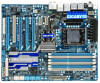
GA-X58A-UD7 Motherboard Layout KB_MS R_SPDIF ATX_12V_2X CMOS_SW USB_1394_ESATA_2 USB_1394_ESATA_1 CPU_FAN CPU Voltage L1/2/3 CPU TEMP L1/2 LGA1366 RST_SW PHASE LED FREQ. LED PW_SW DDR Voltage LED PWR_FAN GA-X58A-UD7 USB_LAN ATX USB30_LAN JMicron JMB362 F_AUDIO NB TEMP L1/2 AUDIO NEC - Gigabyte X58A-UD7 | User Manual - Page 8
GA-X58A-UD7 Motherboard Block Diagram 2 PCI Express x16 4 PCI Express x8 PCIe CLK (100 MHz) or LGA1366 CPU CPU CLK+/- (133 MHz) DDR3 2200/1333/1066/800 MHz Dual/3 Channel Memory 133/100/66/33 IDE Channel GIGABYTE SATA2 PCI Bus T.I. TSB43AB23 CODEC 2 USB 3.0/2.0 Dual BIOS 6 SATA 3Gb/s 12 USB - Gigabyte X58A-UD7 | User Manual - Page 9
manual and follow these procedures: • Prior to installation, do not remove or break motherboard motherboard, CPU or memory. motherboard, make sure the power supply has been turned off. • Before turning on the power, make sure the power supply voltage has been set problem related to the use of - Gigabyte X58A-UD7 | User Manual - Page 10
in the LGA1366 package (Go to GIGABYTE's website for the latest CPU support list.) L3 cache varies with CPU QPI 4.8GT/s, 6.4GT/s Chipset North Bridge: Intel® X58 Express Chipset South Bridge: Intel® ICH10R Memory 6 x 1.5V DDR3 DIMM sockets supporting up to 24 GB of system - Gigabyte X58A-UD7 | User Manual - Page 11
Out connector 1 x clearing CMOS button 2 x IEEE 1394a ports 4 x USB 2.0/1.1 ports 2 x USB 3.0/2.0 ports 2 x eSATA/USB Combo connectors 2 x RJ-45 ports 6 x audio jacks (Center/Subwoofer Speaker Out/Rear Speaker Out/ Side Speaker Out/Line In/Line Out/Microphone) I/O Controller w iTE IT8720 chip - Gigabyte X58A-UD7 | User Manual - Page 12
fan speed control (Note 4) 2 x 16 Mbit flash Use of licensed AWARD BIOS Support for DualBIOS™ PnP 1.0a, DMI 2.0, SM BIOS 2.4, ACPI 1.0b Support for @BIOS Support for Q-Flash Support for Xpress BIOS Rescue Support for Download Center Support for Xpress Install Support for Xpress Recovery2 Support - Gigabyte X58A-UD7 | User Manual - Page 13
peripherals. If you wish to set the frequency beyond the standard specifications, please do so according to your hardware specifications including the CPU, graphics card, memory, hard drive, etc. 1-3-1 Installing the CPU A. Locate the alignment keys on the motherboard CPU socket and the notches on - Gigabyte X58A-UD7 | User Manual - Page 14
B. Follow the steps below to correctly install the CPU into the motherboard CPU socket. Before installing the CPU, make sure to turn off the computer and unplug the power cord from the power outlet to prevent damage - Gigabyte X58A-UD7 | User Manual - Page 15
CPU cooler installation manual for instructions on installing the cooler.) Step 5: After the installation, check the back of the motherboard. If the the power connector of the CPU cooler to the CPU fan header (CPU_FAN) on the motherboard. Use extreme care when removing the CPU cooler because the - Gigabyte X58A-UD7 | User Manual - Page 16
front audio module from your chassis to the F_AUDIO connector on the motherboard, be sure to connect it before installing the Hybrid Silent-Pipe module If you want to set up a water cooling system, be sure to replace the North Bridge heatsink fins with the waterblock before installing the Hybrid - Gigabyte X58A-UD7 | User Manual - Page 17
guidelines before you begin to install the memory: • Make sure that the motherboard supports the memory. It is recommended that memory of the same capacity, brand, speed, and chips be used. (Go to GIGABYTE's website for the latest supported memory speeds and momery moudles.) • Always turn off - Gigabyte X58A-UD7 | User Manual - Page 18
unplug the power cord from the power outlet to prevent damage to the memory module. DDR3 and DDR2 DIMMs are not compatible to each other or DDR DIMMs. Be sure to install DDR3 DIMMs on this motherboard. Notch DDR3 DIMM A DDR3 memory module has a notch, so it can only fit in one direction. Follow - Gigabyte X58A-UD7 | User Manual - Page 19
an expansion card: • Make sure the motherboard supports the expansion card. Carefully read the manual that came with your expansion card. • Always If necessary, go to BIOS Setup to make any required BIOS changes for your expansion card(s). 7. Install the driver provided with the expansion card - Gigabyte X58A-UD7 | User Manual - Page 20
supports Windows Vista and Windows 7 operating systems only - A CrossFireX/SLI-supported motherboard with two/three PCI Express x16 slots and correct driver installing the graphics card driver in the operating system, go to the NVIDIA Control Panel. Browse to the Set SLI and PhysX configuration - Gigabyte X58A-UD7 | User Manual - Page 21
secure the SATA bracket to the chassis back panel with a screw. Step 2: Connect the SATA cable from the bracket to the SATA port on your motherboard. Step 3: Connect the power cable from the bracket to the power supply. Step 4: Plug one end of the SATA signal cable into the external SATA - Gigabyte X58A-UD7 | User Manual - Page 22
connector. Clearing CMOS Button Press the clearing CMOS switch to clear CMOS values. IEEE 1394a Port The IEEE 1394 port supports the connector, first remove the cable from your device and then remove it from the motherboard. • When removing the cable, pull it straight out from the connector. Do - Gigabyte X58A-UD7 | User Manual - Page 23
USB 3.0/2.0 Port The USB 3.0 port supports the USB 3.0 specification and is compatible to the USB 2.0/1.1 specification. Use this port to the default Mic in jack ( ). Refer to the instructions on setting up a 2/4/5.1/7.1-channel audio configuration in Chapter 5, "Configuring 2/4/5.1/7.1-Channel - Gigabyte X58A-UD7 | User Manual - Page 24
Overvoltage LEDs This motherboard contains 4 sets of overvoltage LEDs which indicate the overvoltage level of the CPU, memory, North Bridge, and (High, red) Overclock LEDs The onboard CPU overclock LEDs indicate on which level the CPU is overclocked. The higher the overclock level, the more - Gigabyte X58A-UD7 | User Manual - Page 25
Quick Switches This motherboard has 2 quick buttons: power button and reset button. The power button and reset button allow users to quickly turn on/off or reset the computer - Gigabyte X58A-UD7 | User Manual - Page 26
DDR PHASE LED The number of lighted LEDs indicates the memory loading. The higher the memory loading, the more the number of lighted LEDs. Hardware Installation - 26 - - Gigabyte X58A-UD7 | User Manual - Page 27
devices. • After installing the device and before turning on the computer, make sure the device cable has been securely attached to the connector on the motherboard. - 27 - Hardware Installation - Gigabyte X58A-UD7 | User Manual - Page 28
2x12 Main Power Connector) With the use of the power connector, the power supply can supply enough stable power to all the components on the motherboard. Before connecting the power connector, first make sure the power supply is turned off and all devices are properly installed. The power connector - Gigabyte X58A-UD7 | User Manual - Page 29
orientation (the black connector wire is the ground wire). The motherboard supports CPU fan speed control, which requires the use of a CPU fan with fan speed control design. For optimum heat dissipation, it is recommended that a system fan be installed inside the chassis. 1 CPU_FAN CPU_FAN: Pin No - Gigabyte X58A-UD7 | User Manual - Page 30
a floppy disk drive. The types of floppy disk drives supported are: 360 KB, 720 KB, 1.2 MB, 1.44 2 8) IDE (IDE Connector) The IDE connector supports up to two IDE devices such as hard drives and you wish to connect two IDE devices, remember to set the jumpers and the cabling according to the role - Gigabyte X58A-UD7 | User Manual - Page 31
to SATA 3Gb/s standard and are compatible with SATA 1.5Gb/s standard. Each SATA connector supports a single SATA device. The GIGABYTE SATA2 controller supports RAID 0, RAID 1, and JBOD. Refer to Chapter 5, "Configuring SATA Hard Drive(s)," for instructions on configuring a RAID array. GSATA2_9 - Gigabyte X58A-UD7 | User Manual - Page 32
compatible with SATA 3Gb/s and SATA 1.5Gb/s standards. Each SATA connector supports a single SATA device. The Marvell 9128 supports RAID 0 and RAID 1. Refer to Chapter 5, "Configuring SATA Hard Drive(s)," for instructions such as BIOS configurations, date, and time information) in the CMOS when the - Gigabyte X58A-UD7 | User Manual - Page 33
a beep code. One single short beep will be heard if no problem is detected at system startup. If a problem is detected, the BIOS may issue beeps in different patterns to indicate the problem. Refer to Chapter 5, "Troubleshooting," for information about beep codes. • HD (Hard Drive Activity LED, Blue - Gigabyte X58A-UD7 | User Manual - Page 34
pin assignments of the motherboard header. Incorrect connection between the module connector and the motherboard header will make the device front panel audio header supports HD audio by default. If your chassis provides an AC'97 front panel audio module, refer to the instructions on how to activate - Gigabyte X58A-UD7 | User Manual - Page 35
This header supports digital S/PDIF Out and connects a S/PDIF digital audio cable (provided by expansion cards) for digital audio output from your motherboard to certain digital audio cable, carefully read the manual for your expansion card. 1 Pin No. Definition 1 SPDIFO 2 GND - - Gigabyte X58A-UD7 | User Manual - Page 36
DY+ 7 GND 8 GND 9 No Pin 10 NC When the system is in S4/S5 mode, only the USB ports routed to the F_USB1 header can support the ON/OFF Charge function. • Do not plug the IEEE 1394 bracket (2x5-pin) cable into the USB header. • Prior to installing the USB bracket - Gigabyte X58A-UD7 | User Manual - Page 37
do not encounter problems using the current version of BIOS, it is recommended that you not flash the BIOS. To flash the BIOS, do it with caution. Inadequate BIOS flashing may result in system malfunction. • BIOS will emit a beep code during the POST. Refer to Chapter 5, "Troubleshooting," for the - Gigabyte X58A-UD7 | User Manual - Page 38
v6.00PG, An Energy Star Ally Copyright (C) 1984-2010, Award Software, Inc. Motherboard Model BIOS Version X58A-UD7 Fa1 . . . . : BIOS Setup : XpressRecovery2 : Boot Menu : Qflash 04/23/2010-X58-ICH10-7A89QG0OC-00 Function Keys Function Keys Function Keys: : POST SCREEN - Gigabyte X58A-UD7 | User Manual - Page 39
Sample BIOS Version: Fa1) CMOS Setup Utility-Copyright (C) 1984-2010 Award Software MB Intelligent Tweaker(M.I.T.) Standard CMOS Features Advanced BIOS Features Integrated Peripherals Power Management Setup PC Health Status Load Fail-Safe Defaults Load Optimized Defaults Set Supervisor - Gigabyte X58A-UD7 | User Manual - Page 40
this menu to configure the clock, frequency and voltages of your CPU, memory, etc. Standard CMOS Features Use this menu to configure the system time and date, hard drive types, floppy disk drive types, and the type of errors that stop the system boot, etc. Advanced BIOS Features Use this menu to - Gigabyte X58A-UD7 | User Manual - Page 41
} Advanced Frequency Settings } Advanced Memory Settings } Advanced Voltage Settings } Miscellaneous Settings [Press Enter] [Press Enter] [Press Enter] [Press Enter] [Press Enter] Item Help Menu Level BIOS Version BCLK CPU Frequency Memory Frequency Total Memory - Gigabyte X58A-UD7 | User Manual - Page 42
operating CPU frequency. Advanced CPU Core Features CMOS Setup Utility-Copyright (C) 1984-2010 Award Software Advanced CPU Core Features Intel(R) Turbo Boost Tech. (Note) CPU Cores Enabled (Note) CPU Multi-Threading (Note) CPU Enhanced Halt (C1E) (Note) C3/C6/C7 State Support (Note - Gigabyte X58A-UD7 | User Manual - Page 43
. Note: If your system fails to boot after overclocking, please wait for 20 seconds to allow for automated system reboot, or clear the CMOS values to reset the board to default values. (Default: Disabled) BCLK Frequency(Mhz) Allows you to manually set the CPU base clock. The adjustable range is from - Gigabyte X58A-UD7 | User Manual - Page 44
(Mhz) and System Memory Multiplier settings. PCI Express Frequency(Mhz) Allows you to manually set the PCIe clock frequency. The adjustable range is from 90 MHz to 150 MHz. Auto sets the PCIe clock frequency to standard 100 MHz. (Default: Auto) >>>>> Advanced Clock Control CPU Clock Drive Allows - Gigabyte X58A-UD7 | User Manual - Page 45
Advanced Memory Settings CMOS Setup Utility-Copyright (C) 1984-2010 Award Software Advanced Memory Settings Extreme Memory Profile (X.M.P.) (Note) System Memory Multiplier (SPD) Memory Frequency (Mhz) 1066 Performance Enhance DRAM Timing Selectable (SPD) Profile DDR Voltage Profile - Gigabyte X58A-UD7 | User Manual - Page 46
Settings CMOS Setup Utility-Copyright (C) 1984-2010 Award Software Channel A Timing Settings >>>>> Channel A Standard Timing Control x CAS Latency Time 8 x tRCD 8 x tRP 8 x tRAS 20 >>>>> Channel A Advanced Timing Control Options are: Auto (default), 1~15. BIOS Setup - 46 - - Gigabyte X58A-UD7 | User Manual - Page 47
A/B Misc Timing Control B2B CAS Delay Options are: Auto (default), 1~31. Round Trip Latency Options are: Auto (default), 1~255. >>>>> Channel A/B/C Turnaround Settings CMOS Setup Utility-Copyright are: Auto (default), 1~2. ESC: Exit F1: General Help F7: Optimized Defaults - 47 - BIOS Setup - Gigabyte X58A-UD7 | User Manual - Page 48
F1: General Help F7: Optimized Defaults CMOS Setup Utility-Copyright (C) 1984-2010 Award Software Advanced Voltage Control Ch-C Data VRef. Ch-A Address CPU load. Standard Disables Load-Line Calibration and sets VDroop following Intel specifications. (De- fault) BIOS Setup - 48 - - Gigabyte X58A-UD7 | User Manual - Page 49
CPU Vcore The default is Auto. Dynamic Vcore(DVID) This option is configurable only when CPU Vcore is set to Normal. The default is Auto. QPI/Vtt Voltage The default is Auto. CPU PLL The default Auto. Ch-B Address VRef. The default is Auto. Ch-C Address VRef. The default is Auto. - 49 - BIOS Setup - Gigabyte X58A-UD7 | User Manual - Page 50
} Advanced Frequency Settings } Advanced Memory Settings } Advanced Voltage Settings } Miscellaneous Settings [Press Enter] [Press Enter] [Press Enter] [Press Enter] [Press Enter] Item Help Menu Level BIOS Version BCLK CPU Frequency Memory Frequency Total Memory - Gigabyte X58A-UD7 | User Manual - Page 51
Item Help Menu Level Base Memory Extended Memory Total Memory 640K 1022M 1024M Move Enter: Select F5: Previous Values +/-/PU/PD: Value F10: Save F6: Fail-Safe Defaults ESC: Exit F1: General Help F7: Optimized Defaults Date (mm:dd:yy) Sets the system date. The date format - Gigabyte X58A-UD7 | User Manual - Page 52
boot will not stop for a keyboard or a floppy disk drive error but it will stop for all other errors. Memory These fields are read-only and are determined by the BIOS POST. Base Memory Also called conventional memory. Typically, 640 KB will be reserved for the MS-DOS operating - Gigabyte X58A-UD7 | User Manual - Page 53
BIOS Features CMOS Setup Utility-Copyright (C) 1984-2010 Award Software Advanced BIOS Features } Hard Disk Boot Priority Quick Boot First Boot Device Second Boot Device Third Boot Device Password Check HDD S.M.A.R.T. Capability Limit CPUID Max. to 3 (Note) No-Execute Memory - Gigabyte X58A-UD7 | User Manual - Page 54
For HDD (Secs) Allows you to set a delay time for the BIOS to initialize the hard drive as the GIGABYTE Logo at system startup. Disabled displays normal POST message. (Default: Enabled) Backup BIOS Image to HDD Allows the system to copy the BIOS image file to the hard drive. If the system BIOS - Gigabyte X58A-UD7 | User Manual - Page 55
Bridge) Enables or disables the X.H.D function for the SATA controllers integrated in the Intel ICH10R Chipset. When set to Enabled, the ICH SATA Control Mode item below will be set to RAID(XHD) automatically. For details on using the GIGABYTE X.H.D utility, refer to Chaper 4, "eXtreme Hard Drive - Gigabyte X58A-UD7 | User Manual - Page 56
RAID(XHD) Enables RAID for the SATA controllers. AHCI Configures the SATA controllers to AHCI mode. Advanced Host Controller Interface (AHCI) is an interface specification that allows the storage driver to enable advanced Serial ATA features such as Native Command Queuing and hot plug. - Gigabyte X58A-UD7 | User Manual - Page 57
Function) CMOS Setup LAN cable is attached to the motherboard, the Status fields of all four is activated. When a Cable Problem Occurs... If a cable problem occurs on a specified pair Controller (NEC USB Controller) Enables or disables the NEC USB controller. (Default: Enabled) - 57 - BIOS Setup - Gigabyte X58A-UD7 | User Manual - Page 58
driver to enable advanced Serial ATA features such as Native Command Queuing and hot plug. SATA3 Firmware Selection Determines whether to automatically update the firmware of the Marvell 9128 chip. Onchip Keeps the original firmware version. (Default) Auto Lets the BIOS automatically - Gigabyte X58A-UD7 | User Manual - Page 59
CMOS Setup Utility-Copyright (C) 1984-2010 Award Software Power Management Setup ACPI Suspend Type Soft-Off by PWR-BTTN PME Event Wake Up Power On by Ring Resume by Alarm x Date (of Month) Alarm x Time (hh:mm:ss) Alarm HPET Support Back Function ErP Support [S3(STR to RAM) - Gigabyte X58A-UD7 | User Manual - Page 60
entering the password to clear the password settings. AC Back Function Determines set to Enabled, the following four functions will become unavailable: PME event wake up, power on by mouse, power on by keyboard, and wake on LAN. (Note) Supported on Windows 7/Vista operating system only. BIOS - Gigabyte X58A-UD7 | User Manual - Page 61
detection device attached to the motherboard CI header. If the system chassis cover is removed, this field will show "Yes", otherwise it will show "No". To clear the chassis intrusion status record, set Reset Case Open Status to Enabled, save the settings to the CMOS, and then restart your system - Gigabyte X58A-UD7 | User Manual - Page 62
how to control CPU fan speed. This item is configurable only if CPU Smart FAN Control is set to Enabled. Auto Lets the BIOS automatically detect the type of CPU fan installed and sets the optimal CPU fan control mode. (Default) Voltage Sets Voltage mode for a 3-pin CPU fan. PWM Sets PWM mode - Gigabyte X58A-UD7 | User Manual - Page 63
and most stable BIOS settings for the motherboard. 2-10 Load Optimized Defaults CMOS Setup Utility-Copyright (C) 1984-2010 Award Software MB Intelligent Tweaker(M.I.T.) Load Fail-Safe Defaults Standard CMOS Features Load Optimized Defaults Advanced BIOS Features Set Supervisor Password - Gigabyte X58A-UD7 | User Manual - Page 64
Award Software MB Intelligent Tweaker(M.I.T.) Standard CMOS Features Advanced BIOS Features Integrated Peripherals Power Management SetupEnter Password: PC Health Status Load Fail-Safe Defaults Load Optimized Defaults Set Supervisor Password Set User Password Save & Exit Setup Exit - Gigabyte X58A-UD7 | User Manual - Page 65
Award Software MB Intelligent Tweaker(M.I.T.) Load Fail-Safe Defaults Standard CMOS Features Advanced BIOS Features Load Optimized Defaults Save to CMOS and EXITSe(Yt S/Nup)?erYvisor Password Integrated Peripherals Set User Password Power Management Setup Save & Exit Setup PC - Gigabyte X58A-UD7 | User Manual - Page 66
BIOS Setup - 66 - - Gigabyte X58A-UD7 | User Manual - Page 67
install new GIGABYTE utilities. Click Yes to automatically install the utilities. Or click No if you want to manually select the utilities to install on the Application Software page later. • For USB 2.0 driver support under the Windows XP operating system, please install the Windows XP Service Pack - Gigabyte X58A-UD7 | User Manual - Page 68
applications that GIGABYTE develops and some free software. You can click the Install button on the right of an item to install it. 3-3 Technical Manuals This page provides GIGABYTE's application guides, content descriptions for this driver disk, and the motherboard manuals. Drivers Installation - Gigabyte X58A-UD7 | User Manual - Page 69
3-4 Contact For the detailed contact information of the GIGABYTE Taiwan headquarter or worldwide branch offices, click the URL on this page to link to the GIGABYTE website. 3-5 System This page provides the basic system information. - 69 - Drivers Installation - Gigabyte X58A-UD7 | User Manual - Page 70
Center To update the BIOS, drivers, or applications, click the Download Center button to link to the GIGABYTE website. The latest version of the BIOS, drivers, or applications will be displayed. 3-7 New Utilities This page provides a quick link to GIGABYTE's lately developed utilities for users - Gigabyte X58A-UD7 | User Manual - Page 71
and perform restoration of it. Supporting NTFS, FAT32, and FAT16 sure to leave enough unallocated space in advanced (10 GB or more is recommended soon after the operating system and drivers are installed. • The amount of data At least 512 MB of system memory • VESA compatible graphics card • Windows XP - Gigabyte X58A-UD7 | User Manual - Page 72
note that if there is no enough unallocated space, Xpress Recovery2 cannot save the backup file. B. Accessing Xpress Recovery2 1. Boot from the motherboard driver disk to access Xpress Recovery2 for the first time. When you see the following message: Press any key to startup Xpress Recovery2, press - Gigabyte X58A-UD7 | User Manual - Page 73
D. Using the Restore Function in Xpress Recovery2 Select RESTORE to restore the backup to your hard drive in case the system breaks down. The RESTORE option will not be present if no backup is created before. E. Removing the Backup Step 1: If you wish to remove the backup file, select REMOVE. Step - Gigabyte X58A-UD7 | User Manual - Page 74
file from the nearest @BIOS server 4-2-1 Updating the BIOS with the Q-Flash Utility A. Before You Begin 1. From GIGABYTE's website, download the latest compressed BIOS update file that matches your motherboard model. 2. Extract the file and save the new BIOS file (e.g. X58AUD7.F1) to your floppy - Gigabyte X58A-UD7 | User Manual - Page 75
option allows you to save the current BIOS file. • Q-Flash only supports USB flash drive or hard drives using FAT32/16/12 file system. • If the BIOS update file is saved to a hard drive in RAID/AHCI mode or a hard drive attached to an independent IDE/SATA controller, use the key during the - Gigabyte X58A-UD7 | User Manual - Page 76
devices after a BIOS update, so we recommend that you reload BIOS defaults. CMOS Setup Utility-Copyright (C) 1984-2010 Award Software MB Intelligent Tweaker(M.I.T.) Load Fail-Safe Defaults Standard CMOS Features Load Optimized Defaults Advanced BIOS Features Set Supervisor Password - Gigabyte X58A-UD7 | User Manual - Page 77
. If the BIOS update file for your motherboard is not present on the @BIOS server site, please manually download the BIOS update file from GIGABYTE's website and follow the instructions in "Update the BIOS without Using the Internet Update Function" below. 2. Update the BIOS without Using the - Gigabyte X58A-UD7 | User Manual - Page 78
and motherboard. The Memory tab provides information on the installed memory module(s). You can select memory module on a specific slot to see its information. The Tuner tab allows you to change system clock settings and voltages Quick Boost mode provides you with 3 levels of CPU frequency - Gigabyte X58A-UD7 | User Manual - Page 79
two sets and switch between them) (Default: Off) 13 Close (Application will enter Stealth Mode) 14 Minimize (Application will continue to run in taskbar) 15 INFO/Help 16 Motherboard Phase LED On/Off Switch (Default: On) 17 Live Utility Update (Check for the latest utility version) • The - Gigabyte X58A-UD7 | User Manual - Page 80
to run in taskbar) 14 INFO/Help 15 Motherboard Phase LED On/Off Switch (Default: On) 16 Live Utility Update (Check for the latest utility version) C. Stealth Mode In Stealth Mode, the system continues to work with the user-defined power saving settings, even after the system is restarted. Re - Gigabyte X58A-UD7 | User Manual - Page 81
motherboard driver disk, go to Start>All Programs>GIGABYTE>Q-Share.exe to launch the Q-Share tool. Find the Q-Share icon in your taskbar and right-click on this icon to configure the data sharing settings be shared (Note) Updates Q-Share online Displays the current Q-Share version Exits Q-Share ( - Gigabyte X58A-UD7 | User Manual - Page 82
4-6 Smart 6™ GIGABYTE Smart 6™ (Note 1) is designed with user-friendliness in mind, and Instructions: Select the Enable check box below the BIOS QuickBoot or OS QuickBoot item and then click Save to save the settings. SMART QuickBoost SMART QuickBoost features quick and effortless CPU overclocking - Gigabyte X58A-UD7 | User Manual - Page 83
the recorded data in the main and backup BIOS simultaneously, which can prevent loss of the data in case the system/hard drive fails. Instructions: Enter the Smart 6™ password to launch the SMART DualBIOS utility. In the main screen, you can set up records of personal passwords and important dates - Gigabyte X58A-UD7 | User Manual - Page 84
Instructions (Note 5): Click the lock icon on the bottom left corner and enter the Smart 6™ password. Set The changed data refers to the data that has been modified, deleted, or newly added since the last backup. The . You can set the User Password in the system BIOS Setup program to prevent the system time - Gigabyte X58A-UD7 | User Manual - Page 85
on the Auto Green main menu and click Save to save the settings. Button Standby Suspend Disable Description Enters Power on Suspend mode Enters Suspend to RAM mode Disables this function The Bluetooth dongle included in the motherboard package(Note 2) allows you to wake up the system from - Gigabyte X58A-UD7 | User Manual - Page 86
1: Configure the system BIOS Enter the system BIOS Setup program, set eXtreme Hard Drive (X.H.D) under the Integrated Peripherals menu to Enabled to enable RAID for the Intel SATA controllers. Step 2: Install the RAID driver and operating system The X.H.D utility supports Windows 7/Vista/XP. Before - Gigabyte X58A-UD7 | User Manual - Page 87
supports the IEEE 802.3ad LACP standard. Please refer to your network switch or router device manual for further details. Select Realtek Ethernet Diagnostic Utility and click Install. Step 1: Insert the motherboard driver for the Team, e.g. Teaming, and set up the Teaming mode based on your hub - Gigabyte X58A-UD7 | User Manual - Page 88
Unique Features - 88 - - Gigabyte X58A-UD7 | User Manual - Page 89
create RAID, you may prepare only one hard drive. • An empty formatted floppy disk. • Windows Vista/XP setup disk. • Motherboard driver disk. 5-1-1 Configuring Intel ICH10R SATA Controllers A. Installing SATA hard drive(s) in your computer Attach one end of the SATA signal cable to the rear of the - Gigabyte X58A-UD7 | User Manual - Page 90
Defaults Figure 1 Step 2: Save changes and exit BIOS Setup. The BIOS Setup menus described in this section may differ from the exact settings for your motherboard. The actual BIOS Setup menu options you will see shall depend on the motherboard you have and the BIOS version. Appendix - 90 - - Gigabyte X58A-UD7 | User Manual - Page 91
C. Configuring a RAID array in RAID BIOS Enter the RAID BIOS setup utility to configure a RAID array. Skip this step and proceed with the installation of Windows operating system for a non-RAID configuration. Step 1: After the POST memory test begins and before the operating system boot begins, - Gigabyte X58A-UD7 | User Manual - Page 92
and press . Then, select a RAID level (Figure 4). RAID levels supported include RAID 0, RAID 1, Recovery, RAID 10, and RAID 5 (the will be automatically assigned to the array. Set the stripe block size (Figure 5) if necessary. The stripe block size can be set from 4 KB to 128 KB. Once - Gigabyte X58A-UD7 | User Manual - Page 93
Size 111.7GB 111.7GB Type/Status(Vol ID) Member Disk(0) Member Disk(0) [hi]-Select [ESC]-Exit Figure 7 [ENTER]-Select Menu To exit the RAID BIOS utility, press or select 5. Exit in MAIN MENU. Now, you can proceed to create the SATA RAID/AHCI - Gigabyte X58A-UD7 | User Manual - Page 94
Recovery Volume Options Intel Rapid Recover Technology provides data protection by allowing users to easily restore data and system operation using a designated recovery drive. With the Rapid Recovery Technology, which employs RAID 1 functionality, users can copy the data from the master drive to - Gigabyte X58A-UD7 | User Manual - Page 95
select Continuous or On Request (Figure 11). When set to Continuous, changes made to the data on users to update data from the master drive to the recovery drive manually using the option: On Request: volume is updated manually Continuous: volume is updated automatically [hi]-Change [TAB]-Next - Gigabyte X58A-UD7 | User Manual - Page 96
Delete RAID Volume To delete a RAID array, select Delete RAID Volume in MAIN MENU and press . In the DELETE VOLUME MENU section, use the up or down arrow key to select the array to be deleted and press . When prompted to confirm your selection (Figure 12), press to confirm or - Gigabyte X58A-UD7 | User Manual - Page 97
different SATA Controllers for RAID. Controller Connectors JMicron eSATA ports JMB362 GIGABYTE GSATA2_8/9 SATA2 BIOS Settings Set eSATA Controller to Enabled Set eSATA Ctrl Mode to RAID Set GSATA 8_9/IDE Controller to Enabled Set GSATA 8_9/IDE Ctrl Mode to RAID/IDE CMOS Setup Utility - Gigabyte X58A-UD7 | User Manual - Page 98
. After the POST memory test begins and before the operating system boot begins, look for a message which says "Press to enter RAID Setup Utility" (Figure 2). Press + to enter the RAID setup utility. GIGABYTE Technology Corp. PCI Express to SATAII HOST Controller ROM v1.07.06 - Gigabyte X58A-UD7 | User Manual - Page 99
. Then the Create New RAID screen appears (Figure 4). Gigabyte Technology Corp. RAID Setup Utility v1.07.06 [ Create created RAID drive to be identified by system BIOS or OS. [fg]-Move Cursor [DEL,BS block displays all the items that need to be set for creating an array (Figure 5). Steps: 1. - Gigabyte X58A-UD7 | User Manual - Page 100
After a RAID mode is selected, RAID BIOS automatically assigns the two hard drives installed as the RAID drives. 4. Set Block Size (RAID 0 only): Under confirm your selection (Figure 7), press to confirm or to abort. Gigabyte Technology Corp. RAID Setup Utility v1.07.06 [ Create New RAID ] - Gigabyte X58A-UD7 | User Manual - Page 101
Drive List block. Select the array and press . A small window displaying the array information will appear in the center of the screen (Figure 9). Gigabyte Technology Corp. RAID Setup Utility v1.07.06 [ Main Menu ] Create RAID Disk Drive Delete RAID Disk Drive Revert HDD to Non-RAID Solve - Gigabyte X58A-UD7 | User Manual - Page 102
in the main screen to save your settings before exiting the RAID BIOS utility, then press (Figure 10). SATA RAID/AHCI driver diskette and the installation of the SATA RAID/ AHCI driver and operating system. Save And Exit Setup Exit Without Saving Gigabyte Technology Corp. RAID Setup Utility v1. - Gigabyte X58A-UD7 | User Manual - Page 103
Figure 1 ESC: Exit F1: General Help F7: Optimized Defaults The BIOS Setup menus described in this section may differ from the exact settings for your motherboard. The actual BIOS Setup menu options you will see shall depend on the motherboard you have and the BIOS version. - 103 - Appendix - Gigabyte X58A-UD7 | User Manual - Page 104
WDC WD800JD-22L Information Vendor ID : Device ID : Revision ID : BIOS Version : Firmware Version : PCIe Speed rate : Configure SATA as : 1B4B 91A3 B1 1.0.0.1006 2.1.0.1314 2.56Gbps IDE Mode Help Marvell RAID on chip controller. ENTER: Operation F10: Exit/Save ESC: Return Figure 2 Under - Gigabyte X58A-UD7 | User Manual - Page 105
WDC WD800JD-22L RAID Level : Max Size (MB) : Stripe Size : Gigabyte Rounding : Quick Init : VD Name settings above, move to Next and press to begin creating the array. When prompted to confirm whether to create this array, press to confirm or to cancel (Figure 5). Marvell BIOS - Gigabyte X58A-UD7 | User Manual - Page 106
Device ID : Revision ID : BIOS Version : Firmware Version : PCIe Speed rate : Configure SATA as : 1B4B 91A3 B1 1.0.0.1006 2.1.0.1314 2.56Gbps IDE Mode Help Marvell RAID on chip controller. ENTER: Operation F10: Exit/Save ESC: Return Figure 6 7. Save the Settings and Exit. After you complete - Gigabyte X58A-UD7 | User Manual - Page 107
Vendor ID : Device ID : Revision ID : BIOS Version : Firmware Version : PCIe Speed rate : Configure SATA as : set up an array or view the current array status in the operating system. To install the utility, insert the motherboard driver disk, then go to Application Software\Install GIGABYTE - Gigabyte X58A-UD7 | User Manual - Page 108
Vista, you also can copy the SATA controller driver from the motherboard driver disk to a USB flash drive. See the instructions below about how to copy the driver in MS-DOS and Windows mode. In MS-DOS mode: Prepare a startup disk that has CD-ROM support and a blank formatted floppy disk. Steps - Gigabyte X58A-UD7 | User Manual - Page 109
the motherboard driver disk. 2: From your optical drive folder, double click the Menu.exe file in the BootDrv folder (Figure 4). A Command Prompt window will open similar to that in Figure 5. 3: Insert the blank formatted disk. Depending on the operating system to be installed, select the controller - Gigabyte X58A-UD7 | User Manual - Page 110
and Operating System With the SATA RAID/AHCI driver diskette and correct BIOS settings, you are ready to install Windows Vista/ Series SATA RAID Controller and press . Windows Setup You have chosen to configure a SCSI Adapter for use with Windows, using a device support disk provided by - Gigabyte X58A-UD7 | User Manual - Page 111
menu similar to Figure 3 below will appear. Select RAID/AHCI Driver for GIGABYTE GBB36X Controller (x32) and press . Windows Setup You have chosen to configure a SCSI Adapter for use with Windows, using a device support disk provided by an adapter manufacturer. Select the SCSI Adapter - Gigabyte X58A-UD7 | User Manual - Page 112
load the SATA AHCI driver first when installing Windows Vista onto the RAID drives attached to the Marvell 9128 controller. For the Intel ICH10R USB flash drive). Then use Method B to load the driver. Method A: Insert the motherboard driver disk into your system and browse to the following directory - Gigabyte X58A-UD7 | User Manual - Page 113
Step 3: When a screen as shown in Figure 7 appears, select Intel(R) ICH8R/ICH9R/ICH10R/DO/5 Series/3400 Series SATA RAID Controller and click Next. Figure 7 Step 4: After the driver is loaded, select the RAID/AHCI drive(s) where you want to install the operating system and then click Next to - Gigabyte X58A-UD7 | User Manual - Page 114
(go to the BootDrv folder and save the whole GSATA folder to the USB flash drive). Then use Method B to load the driver. Method A: Insert the motherboard driver disk into your system and browse to the following directory: \BootDrv\GSATA\32Bit For Windows Vista 64-bit, browse to the 64Bit folder - Gigabyte X58A-UD7 | User Manual - Page 115
Step 3: When a screen as shown in Figure 11 appears, select GIGABYTE GBB36X Controller and click Next. Figure 11 Step 4: After the driver is loaded, select the RAID/AHCI drive(s) where you want to install the operating system and then click Next to continue the OS installation (Figure - Gigabyte X58A-UD7 | User Manual - Page 116
area, which will show that a RAID volume is being rebuilt). If you do not enable automatic rebuild on this stage, you have to manually rebuild the array in the operating system (see the next page for more details). Intel(R) Rapid Storage Technology - option ROM - 9.5.0.1037 Copyright(C) 2003 - Gigabyte X58A-UD7 | User Manual - Page 117
• Performing the Rebuild in the Operating System While in the operating system, make sure the chipset driver has been installed from the motherboard driver disk. Then launch the Intel Rapid Storage Technology utility from All Programs in the Start menu. Step 1: Go to the Manage menu and click - Gigabyte X58A-UD7 | User Manual - Page 118
State (for Recovery Volume only) When two hard drives are set to Recovery Volume in Update on Request mode, you can restore the master drive data to the recovery drive in the operating system. Follow the on-screen instructions to complete and exit the RAID Configuration Utility. Intel(R) Rapid - Gigabyte X58A-UD7 | User Manual - Page 119
RAID rebuilding process. The rebuilding progress is displayed at the bottom of the screen. When done, the status of the array will display as Normal. Gigabyte Technology Corp. RAID Setup Utility v1.07.06 [ Main Menu ] Create RAID Disk Drive Delete RAID Disk Drive Revert HDD to Non-RAID Solve - Gigabyte X58A-UD7 | User Manual - Page 120
in the operating system Make sure the JMicron JMB362/GIGABYTE SATA2 SATA controller driver has been installed from the motherboard driver disk. Launch the GIGABYTE RAID CONFIGURER from All Programs in the Start menu. Step 1: In the GIGABYTE RAID CONFIGURER screen, right-click on the array to - Gigabyte X58A-UD7 | User Manual - Page 121
the selection bar to the array to be rebuilt (for example, VD 0: New_VD) and press and then select Rebuild. Press again. Marvell BIOS Setup (c) 2009 Marvell Technology Group Ltd. Topology HBA 0 : Marvell 0 Virtual Disks VD 0: New_VD PD 8: WDC WD8[0D0JeDle-t2e]2L Free Physical Disks - Gigabyte X58A-UD7 | User Manual - Page 122
% Number of PDs : 2 Numbers : 08 Help Virtual Disk: A set of disk blocks presented to an operating environment as a range of consecutively To resume the stopped rebuild process, enter the GSATA RAID Configuration menu in BIOS Setup again. Move the selection bar to the array to be rebuilt (for - Gigabyte X58A-UD7 | User Manual - Page 123
audio driver. For manually configure the jack for microphone functionality. • Audio signals will be present on both of the front and back panel audio connections simultaneously. If you want to mute the back panel audio (only supported when using an HD front panel audio module), refer to instructions - Gigabyte X58A-UD7 | User Manual - Page 124
box. Click OK to complete. D. Muting the Back Panel Audio (For HD Audio Only) Click Device advanced settings on the top right corner on the Speaker Configuration tab to open the Device advanced settings dialog box. Select the Mute the rear output device, when a front headphone plugged in check box - Gigabyte X58A-UD7 | User Manual - Page 125
S/PDIF In 1. Installing the S/PDIF In Cable: Step 1: First, attach the connector at the end of the cable to the SPDIF_I header on your motherboard. Step 2: Secure the metal bracket to the chassis back panel with a screw. 2. Configuring S/PDIF In: On the Digital Input screen, click the Default - Gigabyte X58A-UD7 | User Manual - Page 126
Format tab and then select the sample rate and bit depth. Click OK to complete. (Note) Enter the Digital Output(Optical) screen to configure further settings if you use the S/PDIF Out connector(s) on the back panel for digital audio output or enter the Digital Output screen if you use the - Gigabyte X58A-UD7 | User Manual - Page 127
channel audio, creating a virtual surround sound environment . (Note) Install the Dolby GUI Software driver from the motherboard driver disk. Click the Start icon Programs, Dolby Control Center to access the utility. (The following illustration demonstrates a 7.1-speaker configuration as an example - Gigabyte X58A-UD7 | User Manual - Page 128
Configuring Microphone Recording Step 1: After installing the audio driver, the HD Audio Manager icon will appear in during the recording process, do not mute the playback volume. It is recommended that you set the volumes at a middle level. If you want to change the current sound input default - Gigabyte X58A-UD7 | User Manual - Page 129
playback volume for the microphone, click the Microphone Boost icon on the right of the Recording Volume slider and set the Microphone Boost level. Step 5: After completing the settings above, click Start, point to All Programs, point to Accessories, and then click Sound Recorder to begin the sound - Gigabyte X58A-UD7 | User Manual - Page 130
When the Stereo Mix item appears, right-click on this item and select Enable. Then set it as the default device. Step 4: Now you can access the HD Audio Manager the Recorded Sound You can play your recording in a digital media player program that supports your audio file format. Appendix - 130 - - Gigabyte X58A-UD7 | User Manual - Page 131
5-3 Troubleshooting 5-3-1 Frequently Asked Questions To read more FAQs for your motherboard, please go to the Support&Downloads\Motherboard\FAQ page on GIGABYTE's website. Q: In the BIOS Setup program, why are some BIOS options missing? A: Some advanced options are hidden in the BIOS Setup program - Gigabyte X58A-UD7 | User Manual - Page 132
Procedure If you encounter any troubles during system startup, follow the troubleshooting procedure below to solve the problem. START Turn off the power. Remove all peripherals, connecting cables, and power cord etc. Make sure the motherboard does not short-circuit with the chassis or - Gigabyte X58A-UD7 | User Manual - Page 133
"Save & Exit Setup" to save changes and exit BIOS Setup. The problem is verified and solved. Turn off the computer and connect problem, contact the place of purchase or local dealer for help. Or go to the Support&Downloads\Technical Service Zone page to submit your question. Our customer service - Gigabyte X58A-UD7 | User Manual - Page 134
to copy BIOS back to E000 & F000 shadow RAM Expand the Xgroup codes locating in physical address 1000:0 DualBIOS init (optional) Initial Superio_Early_Init switch 1. Blank out screen 2. Clear CMOS error flag 1. Clear 8042 interface 2. Initialize 8042 self-test 1. Test special keyboard controller for - Gigabyte X58A-UD7 | User Manual - Page 135
memory address 2. Initialize the APIC for Pentium class CPU 3. Program early chipset according to CMOS setup Example: onboard IDE controller 4. Measure CPU speed Invoke video BIOS USB Keyboard & Mouse Test all memory (clear all extended memory to 0) Clear password according to H/W jumper (optional - Gigabyte X58A-UD7 | User Manual - Page 136
floppy controller 2. Set up floppy related fields in 40:hardware Detect & install all IDE devices: HDD, LS120, ZIP, CDROM... Detect serial ports & parallel ports Detect & install co-processor Init HDD write protect 1. Switch back to text mode if full screen logo is supported - If errors occur - Gigabyte X58A-UD7 | User Manual - Page 137
final initialization 5. Power management final initialization 6. Clear screen & display summary table 7. Boot BIOS support (popup menu) Update keyboard LED & typematic rate 1. Build MP table 2. Initialize power-saving (optional) 3. Set CMOS century to 20h or 19h 4. Load CMOS time into DOS timer tick - Gigabyte X58A-UD7 | User Manual - Page 138
errors or omissions in this text. Also note that the information in this document is subject to change without notice and should not be construed as a commitment by GIGABYTE. Our Commitment to Preserving the Environment In addition to high-efficiency performance, all GIGABYTE motherboards service or - Gigabyte X58A-UD7 | User Manual - Page 139
Finally, we suggest that you practice other environmentally friendly actions by understanding and using the energy-saving features of this product (where applicable), recycling the inner and outer packaging (including shipping containers) this product was delivered in, and by disposing of or - Gigabyte X58A-UD7 | User Manual - Page 140
Appendix - 140 - - Gigabyte X58A-UD7 | User Manual - Page 141
- 141 - Appendix - Gigabyte X58A-UD7 | User Manual - Page 142
Appendix - 142 - - Gigabyte X58A-UD7 | User Manual - Page 143
231, Taiwan TEL: +886-2-8912-4000 FAX: +886-2-8912-4003 Tech. and Non-Tech. Support (Sales/Marketing) : http://ggts.gigabyte.com.tw WEB address (English): http://www.gigabyte.com.tw WEB address (Chinese): http://www.gigabyte.tw • G.B.T. INC. - U.S.A. TEL: +1-626-854-9338 FAX: +1-626-854-9339 Tech - Gigabyte X58A-UD7 | User Manual - Page 144
, select your language in the language list on the top right corner of the website. • GIGABYTE Global Service System To submit a technical or non-technical (Sales/Marketing) question, please link to: http://ggts.gigabyte.com.tw Then select your language to enter the system. Appendix - 144 -
-
 1
1 -
 2
2 -
 3
3 -
 4
4 -
 5
5 -
 6
6 -
 7
7 -
8
-
9
-
10
-
11
-
12
-
13
-
14
-
15
-
16
-
17
-
18
-
19
-
20
-
21
-
22
-
23
-
24
-
25
-
26
-
27
-
28
-
29
-
30
-
31
-
32
-
33
-
34
-
35
-
36
-
37
-
38
-
39
-
40
-
41
-
42
-
43
-
44
-
45
-
46
-
47
-
48
-
49
-
50
-
51
-
52
-
53
-
54
-
55
-
56
-
57
-
58
-
59
-
60
-
61
-
62
-
63
-
64
-
65
-
66
-
67
-
68
-
69
-
70
-
71
-
72
-
73
-
74
-
75
-
76
-
77
-
78
-
79
-
80
-
81
-
82
-
83
-
84
-
85
-
86
-
87
-
88
-
89
-
90
-
91
-
92
-
93
-
94
-
95
-
96
-
97
-
98
-
99
-
100
-
101
-
102
-
103
-
104
-
105
-
106
-
107
-
108
-
109
-
110
-
111
-
112
-
113
-
114
-
115
-
116
-
117
-
118
-
119
-
120
-
121
-
122
-
123
-
124
-
125
-
126
-
127
-
128
-
129
-
130
-
131
-
132
-
133
-
134
-
135
-
136
-
137
-
138
-
139
-
140
-
141
-
142
-
143
-
144
 |
 |

GA-X58A-UD7
LGA1366 socket motherboard for Intel
®
Core
™
i7 processor family
User's Manual
Rev. 2001
12ME-X58AUD7-2001R