Haier 2HUM18HB03 User Manual
Haier 2HUM18HB03 Manual
 |
View all Haier 2HUM18HB03 manuals
Add to My Manuals
Save this manual to your list of manuals |
Haier 2HUM18HB03 manual content summary:
- Haier 2HUM18HB03 | User Manual - Page 1
Manual of Room Air Conditioner Preparation ƽ Place, robust not causing vibration, where the body can be supported sufficiently. ƽ Place, not affected by heat or steam generated in of indoor and outdoor units The models adopt HFC free refrigerant R410A Attention must be paid to the rising up of - Haier 2HUM18HB03 | User Manual - Page 2
under piping pipe Heat insulation material Lid for left piping Drain hose Piping Pipe supporting plate Fix with adhesive tape ƽ Indoor/outdoor electric cable and drain hose must be bound with refrigerant piping by protecting tape. [ Other direction piping ] ƽ Cut away, with a nipper, the lid - Haier 2HUM18HB03 | User Manual - Page 3
must be replaced by the manufacturer or its service agent or a similar qualified person. refrigerant is needed, according to 20 g/m. But the charge of refrigerant must be conducted by professional air conditioner engineer. Before adding additional refrigerant, perform air purging from the refrigerant - Haier 2HUM18HB03 | User Manual - Page 4
cap Service port cap Valve rod cap CAUTION ƽ Each indoor unit musts to be vacuumed , according to the above steps. ƽ If the refrigerant of the air conditioner leaks, it is necessary to discharge all the refrigerant. Vacuumize first, then charge the liquid refrigerant into air conditioner according - Haier 2HUM18HB03 | User Manual - Page 5
Manual de instalación de aparato de aire acondicionado Preparación Herramientas necesarias para realizar la instalación en el que puedan conectarse los tubos a la unidad exterior. Asegúrese de que el aire frío pueda distribuirse uniformemente por la sala. Coloque la unidad interior cerca de una toma - Haier 2HUM18HB03 | User Manual - Page 6
Accesorios Control remoto (1) Batería seca R-03 (2) Manguera de drenaje (1) Acolchado (4) Placa de montaje(1) Tapón de plástico (4) Tornillo Ø4X25 (4) Codo de drenaje (1) Placa de soporte del tubo (1). Selección de tubo Tubo de líquido (Ø) Tubo de gas (Ø) 6,35mm (1/4") 9,52mm (3/8") NOTA: El - Haier 2HUM18HB03 | User Manual - Page 7
20 g/m. No obstante, la carga de refrigerante deberá ser realizada por un ingeniero profesional en aire acondicionado. Antes de añadir refrigerante adicional, realice una purga de aire desde los tubos refrigerantes y la unidad interior utilizando una bomba de vacío y cargue después el refrigerante - Haier 2HUM18HB03 | User Manual - Page 8
otros medios de refrigeración (excepto el especificado, R410A) o aire en el sistema de circulación del refrigerante. Si ocurriese, se la prueba ■ Explique al cliente cómo utilizar el aparato utilizando el manual de instrucciones. Compruebe los siguientes puntos de prueba Escriba una marca en - Haier 2HUM18HB03 | User Manual - Page 9
i terremoti ed i forti venti. Se la vibrazione può avere influenza sulla casa, fissare l'unità usando un pannello antivibrazione. Leggere questo manuale prima dell'installazione Spiegare all'utente in modo esauriente il funzionamento e l'uso del condizionatore in base alle istruzioni di questo - Haier 2HUM18HB03 | User Manual - Page 10
Telecomando (1) Batteria a secco R-03 (2) Parti accessorie Tubo di scarico (1) Cuscino (4) Piastra di montaggio (1) Giunto a gomito dello scarico (1) Coperchio di plastica (4) Viti Ø4X25 (4) Piastra di supporto tubature (1) Selezione dei tubi Tubo per liquidi (Ø) Tubo per gas (Ø) 6.35mm - Haier 2HUM18HB03 | User Manual - Page 11
Unità interna A Unità esterna A Unità esterna B Unità interna B ALIMENTAZIONE Cavo d'alimentazione: ≥3G*2.5mm2 Unità interna A Unità esterna A Unità interna B Unità esterna B ALIMENTAZIONE Unità da esterno Installazione dell'unità esterna Installare attenendosi allo schema per l' - Haier 2HUM18HB03 | User Manual - Page 12
■ Controllo dell'installazione e collaudo Spiegare accuratamente al cliente come funziona e come si usa il condizionatore in base alle istruzioni del manuale d'uso. Elenco di controllo per il collaudo □ Mettere il segno √ nelle caselle □ Perdita di gas sui collegamenti dei tubi? □ Isolamento - Haier 2HUM18HB03 | User Manual - Page 13
ée à l'unité extérieure. L'emplacement doit permettre de répartir l'air froid dans toute la pièce. L'emplacement doit disposer d'une prise l'unité doit être installée sur un mur, un toit ou la toiture, fixez un support avec des clous ou des fils en tenant compte des séismes et vents forts. Si des - Haier 2HUM18HB03 | User Manual - Page 14
érieures Couvercle pour tuyauterie de droite Couvercle de dessous Couvercle pour tuyauterie de gauche Matériau d'isolation thermique Tuyau de vidange Tuyauterie Plaque de support de tuyau Fixez avec du ruban adhésif Le câble des unités intérieures/extérieures et le tuyau de vidange doivent être - Haier 2HUM18HB03 | User Manual - Page 15
20 g/m. Toutefois, la charge de réfrigérant doit être exécuté par un professionnel de la climatisation Avant d'ajouter du réfrigérant, purgez l'air des tuyaux de réfrigération et de l'unité intérieure avec pompe à vide. Chargez ensuite le réfrigérant supplémentaire. AVERTISSEMENT Unité int - Haier 2HUM18HB03 | User Manual - Page 16
frigérant du climatiseur fuit, il faut vidanger tout le réfrigérant. Mettez d'abord sous vide, puis chargez le réfrigérant liquide dans le climatiseur d'air jusqu'à la quantité indiquée sur la plaque signalétique. Ne laissez pas les autres moyens de réfrigération, sauf pour celui spécifié (R410A) ou
-
 1
1 -
 2
2 -
 3
3 -
 4
4 -
 5
5 -
 6
6 -
 7
7 -
8
-
9
-
10
-
11
-
12
-
13
-
14
-
15
-
16
 |
 |
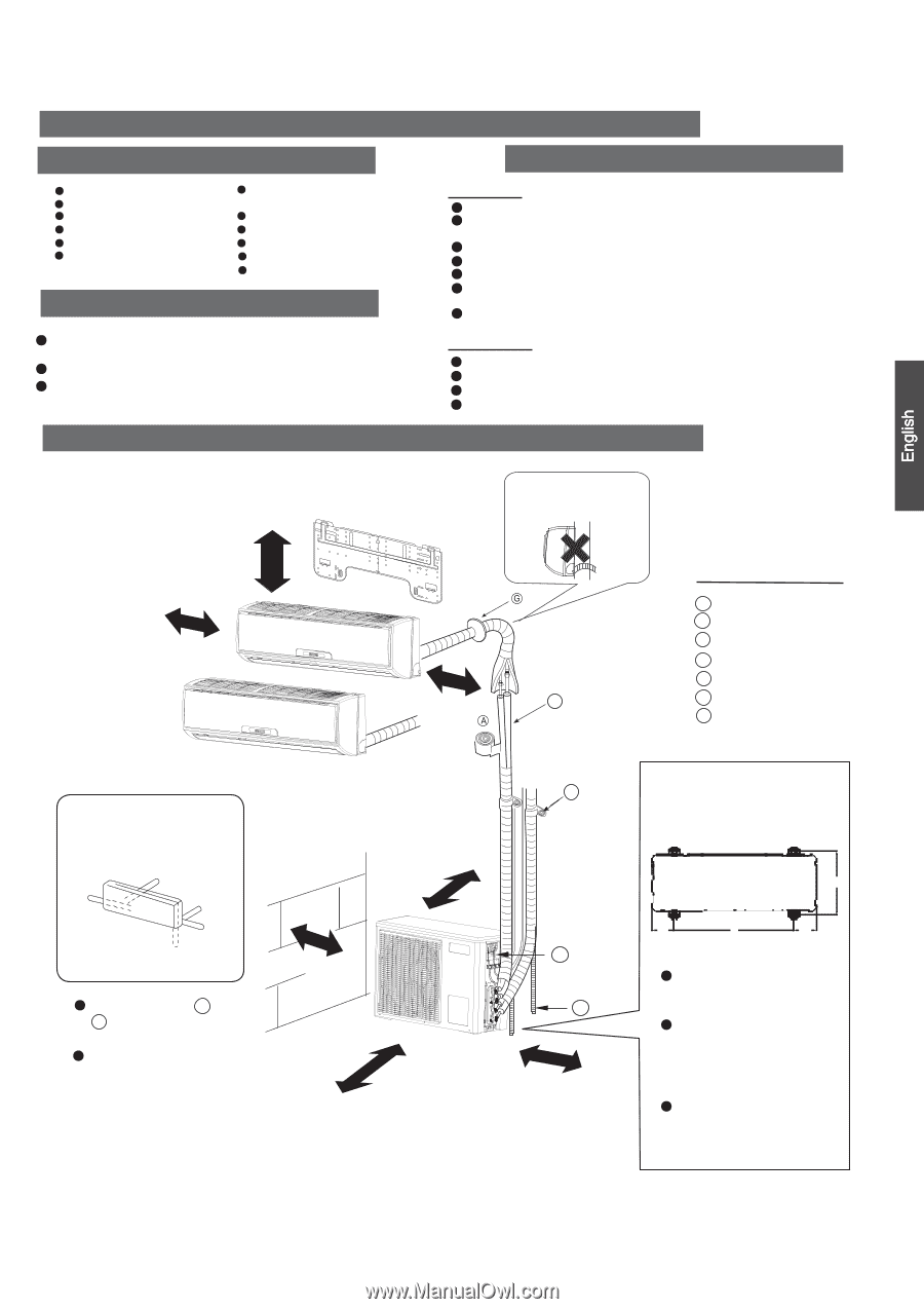
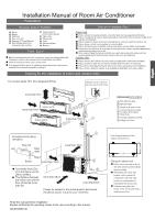
Drawing for the installation of indoor and outdoor units
Necessary Tools for Installation
Driver
Torque wrench
(17mm,22mm,26mm)
Nipper
Reamer
Hacksaw
Pipe cutter
Gas leakage detector or
soap-and-water solution
Hole core drill
Flaring tool
Spanner(17,19 and 26mm)
Knife
Measuring tape
Indoor Unit
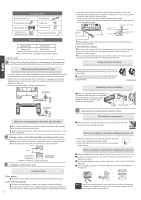
Place, robust not causing vibration, where the body can be supported sufficiently.
Place, not affected by heat or steam generated in the vicinity, where inlet and outlet of the
unit are not disturbed.
Place, possible to drain easily, where piping can be connected with the outdoor unit.
Place, where cold air can be spread in a room entirely.
Place, nearby a power receptacle, with enough space around. (Refer to drawings).
Place where the distance of more than lm from televisions, radios, wireless apparatuses
and fluorescent lamps can be left.
In the case of fixing the remote controller on a wall, place where the indoor unit can
receive signals when the fluorescent lamps in the room are lightened.
Outdoor Unit
Place, which is less affected by rain or direct sunlight and is sufficiently ventilated.
Place, possible to bear the unit, where vibration and noise are not increased.
Place, where discharged wind and noise do not cause a nuisance to the neighbors.
Place, where a distance marked
±
is available as illustrated in the above figure.
Before inserting power plug into receptacle, check the voltage without fail.
The power source is the same as the corresponding name plate.
Install an exclusive branch circuit of the power.
A receptacle shall be set up in a distance where the power cable can be
reached.Do not extend the cable by cutting it.
Selection of Installation Place
Power
Source
Preparation
Read this manual before installation
Explain sufficiently the operating means to the user according to this manual
NO.00105
31140
Installation Manual of Room Air Conditioner
F
C
Optional parts for piping
Non-adhesive tape
Adhesive tape
Saddle (L.S) with screws
Connecting electric cable
for indoor and outdoor
Drain hose
Heating insulating material
Piping hole cover
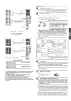
Floor fixing dimensions of the
outdoor unit (Unit:mm)
Fixing of outdoor unit
Fix the unit to concrete or block
with bolts (10mm) and nuts firmly
and horizontally.
When fitting the unit to wall
surface, roof or rooftop, fix
a supporter surely with nails
or wires in consideration of
earthquake and strong wind.
If vibration may affect the
house, fix the unit by attaching a
vibration-proof mat.
The marks from
to
in the figure are the
parts numbers.
The distance between
the indoor unit and the
floor should be more
than 2m.
The models adopt HFC free refrigerant R410A
more than10cm
more than 5cm
more than 10cm
more than 10cm
more than15cm
more than 60cm
A
G
106.5
106.5
566
317
A
F
C
E
D
G
B
Arrangement of piping
directions
Rear left
Left
Rear
right
Right
Below
Please be subject to the actual product purchased ,
the above picture is just for your reference.
Attention must be paid to
the rising up of drain hose
Indoor unit A
Indoor unit B
E
D
more than 10cm