Haier HC36D1VAR User Manual
Haier HC36D1VAR Manual
 |
View all Haier HC36D1VAR manuals
Add to My Manuals
Save this manual to your list of manuals |
Haier HC36D1VAR manual content summary:
- Haier HC36D1VAR | User Manual - Page 1
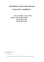
Installation & Operation Manual Central Air Conditioner 10 to 13 SEER 1.5 to 5 Tons Models: HC18-60A1VAR/S HC18-60C1VAR HC18-60D1VAR No.0010572324 K The information contained in this booklet is subject to change without notice. - Haier HC36D1VAR | User Manual - Page 2
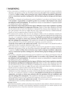
the introduction and disposal of refrigerants in this unit. Failure to air conditioner and may also endanger life and property. The manufacturer disclaims any responsibility for such loss or injury resulting from the use of such unauthorized components, accessories or devices. Attach the service - Haier HC36D1VAR | User Manual - Page 3
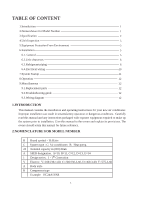
6 6.3.Refrigerant piping 6 6.4.Electrical wiring 10 7.System Startup 11 8.Operation 12 9.Miscellaneous 12 9.1.Replacement parts 12 9.2.Troubleshooting guide 12 9.3.Wiring diagram 12 1.INTRODUCTION This manual contains the installation and operating instructions for your new air conditioner - Haier HC36D1VAR | User Manual - Page 4
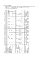
3.SPECIFICATION The dimensions for the condensing unit are illustrated in Figure 1. Physical and electrical specifications are provided in Table 1 for 10 SEER systems respectively. Table 1: Model:HC18-60A1VAR/S 2 MODEL: HC18A1VAR HC24A1VAR HC30A1VAR HC36A1VAS HC42A1VAR HC48A1VAR HC60A1VAR Unit - Haier HC36D1VAR | User Manual - Page 5
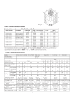
Figure 1 Outdoor Unit With This Indoor Air handler Model Number Air Handler Compressor Cooling Capacity (Btu/h) SEER 60C1VAR MODEL: Unit Supply Voltage Normal Voltage Range HC18C1VAR HC24C1VAR HC30C1VAR HC36C1VAR 208/230-1-60 197 - 253 HC42C1VAR HC48C1VAR HC60C1VAR Bristol Compressor - Haier HC36D1VAR | User Manual - Page 6
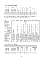
Number HC18C1VAR HC24C1VAR HC30C1VAR HC36C1VAR HC42C1VAR HC48C1VAR HC60C1VAR With This Indoor Air handler Air Handler Compressor Cooling Model Number HC18D1VAR HC24D1VAR HC30D1VAR HC36D1VAR HC42D1VAR HC48D1VAR HC60D1VAR With This Indoor Air handler Air Handler Compressor Cooling Capacity (Btu - Haier HC36D1VAR | User Manual - Page 7
. 5.EQUIPMENT PROTECTION FROM ENVIRONMENT The metal parts of the unit may be subject to an area where contaminants are likely to be a problem, special attention should be given to the equipment location Structural strength of supporting members. Clearances and provision for servicing. Power supply - Haier HC36D1VAR | User Manual - Page 8
sure the building construction can support the weight and that proper roof. The condensing unit contains moving parts and can vibrate. Therefore, sound air enters from three sides. Air discharges upward from the top of the unit. Refrigerant tube and electrical connections are made from the service - Haier HC36D1VAR | User Manual - Page 9
or bends, to avoid capacity loss and increased operating costs. Refrigerant lines must be adequately supported. If metal strapping is used to secure the tubing, do on the piping and to prevent heat gain caused by surrounding air. Generally 3/8" wall thickness of Armflex or equivalent is satisfactory - Haier HC36D1VAR | User Manual - Page 10
the liquid line to remove pressure. ! CAUTION - Condensing units are charged with refrigerant. Condensing unit liquid and suction valves are closed to contain the charge within the indoor liquid pipe orifice. Instructions on the field tubing connections and valve opening procedure are as follow: 8 - Haier HC36D1VAR | User Manual - Page 11
from entering the system. 2.Make sure that both refrigerant stop valves at the outdoor unit are closed. 3. 4.Remove the cap and Schrader valve core from the service port to protect the valve seals. 5.Wrap a removed prior to charging the system. Air in a system causes high condensing pressure - Haier HC36D1VAR | User Manual - Page 12
service gage manifold to the valve service ports, being sure to evacuate lines. 3.Startup the system (Refer to the Section 7 - "System Startup"). Run system at least 10 minutes to allo System Superheat Ambient Return Air this appliance at the electrical service entrance. manual this instruction). - Haier HC36D1VAR | User Manual - Page 13
run in cooling mode. 5.Check to see if compressor and outdoor fan are running correctly? 6.Check the refrigerant charge (see Instructions under "Charging the System"). 7.Replace service port caps. Service port cores are for system access only and will leak if not tightly capped. 8.Check unit for - Haier HC36D1VAR | User Manual - Page 14
automatic open overload device or blow a fuse. Poor electrical service can cause nuisance tripping in overloads or blow fuses. The Parts Contact your local distributor for a complete parts list. 9.2. Troubleshooting Guide Refer to the troubleshooting guide (Table 10) included in this manual - Haier HC36D1VAR | User Manual - Page 15
load Insufficient Cooling Improper airflow Check - should be 400CFM/Ton Incorrect refrigerant charge Charge correctly per instruction. Air, non-condensibles or moisture in system Recover refrigerant, evacuate & recharge, add filter drier Incorrect voltage At compressor terminals, voltage - Haier HC36D1VAR | User Manual - Page 16
HC18-60A1VAR/S HC18-60C1VAR HC18-60D1VAR Air Conditioner Wi ri ng Diagram 5 YL 6C S R RD BK RD OFM 6 M BR R S BR BK PU L1 BK L2 WH GND 208 power connect ions di rect ly to elect ric h eater kit pow er terminals. Consult heat er ki t inst allation instructions for complete det ails. 14 - Haier HC36D1VAR | User Manual - Page 17
Made in P.R.C.
-
 1
1 -
 2
2 -
 3
3 -
 4
4 -
 5
5 -
 6
6 -
 7
7 -
8
-
9
-
10
-
11
-
12
-
13
-
14
-
15
-
16
-
17
 |
 |

No.0010572324
K
10 to 13 SEER
1.5 to 5 Tons
Models: HC18-60A1VAR/S
HC18-60C1VAR
HC18-60D1VAR
Installation & Operation Manual
Central Air Conditioner
The information contained in this booklet is subject to change without notice.