Haier HSU-09LEK13 User Manual
Haier HSU-09LEK13 Manual
 |
View all Haier HSU-09LEK13 manuals
Add to My Manuals
Save this manual to your list of manuals |
Haier HSU-09LEK13 manual content summary:
- Haier HSU-09LEK13 | User Manual - Page 1
to the user according to this manual. Necessary Tools for Installation 1.Driver or soap-and-water solution 11.Measuring tape 12.Reamer Drawing for the installation of indoor 1 8 Cover 1 9 Cushion 4 10 1 Pipe supporting plate 11 Connecting cable 1 Arrangement of piping directions Rear - Haier HSU-09LEK13 | User Manual - Page 2
HSU-12LEK13 HSU-07LEK03 HSU-07HEK03 HSU-09LEK03 HSU-12LEK03 HSU-09HEK03 HSU-12HEK03 Fixing of outdoor unit Fix the unit to concrete or block with bolts( 10mm) and nuts firmly and horizontally. When fitting the unit to wall surface, roof or rooftop, fix a supporter 12 6.35mm(1/4") 12.7mm(1/2") 2 - Haier HSU-09LEK13 | User Manual - Page 3
Indoor unit Indoor unit 1.Fitting of the Mounting Plate and Positioning of the wall Hole When the mounting plate is first fixed 1.Carry out, based on the neighboring pillars or lintels, a proper leveling for the plate to be fixed against the wall, then temporarily fasten the plate with one steel - Haier HSU-09LEK13 | User Manual - Page 4
Indoor unit 1. Insert the drain hose into the dent of heat insulation materials of indoor unit. 2. Insert the indoor/outdoor electric cable from backside of indoor unit, and pull it out on the front side, then connect them. 3. Coat the flaring seal face with refrigerant oil and connect pipes. Cover - Haier HSU-09LEK13 | User Manual - Page 5
by the manufacturer or its service agent or a similar qualified HSU-07LEK03 HSU-09LEK03 HSU-12LEK03 HSU-09LEK13 HSU-12LEK13 connecting wiring: -mod 07-12: 3G1.0mm Power cable: -mod 07-12: 3G1.0mm Indoor unit Outdoor unit HSU-07HEK03 HSU-09HEK03 HSU-12HEK03 connecting wiring: -mod 07-12 - Haier HSU-09LEK13 | User Manual - Page 6
centering may damage the threads and cause a leakage of gas. Pipe Diameter ( ) Fastening torque Liquid side 6.35mm(1/4") Gas side 9.52mm(3/8") Gas side 12.7mm(1/2") 18N.m 42N.m 50N.m Be careful that matters, such as wastes of sands, etc. shall not enter the pipe. 3.Connection Use the same - Haier HSU-09LEK13 | User Manual - Page 7
Additional amount No need 40g 100g 2-way valve 6.35mm(1/4") 6.35mm(1/4") 3-way valve 9.52mm(3/8") 12.70mm(1/2") HSU-07LEK03 HSU-09LEK03 HSU-12LEK03 HSU-09LEK13 HSU-12LEK13 HSU-07HEK03 HSU-09HEK03 HSU-12HEK03 Indoor unit A Outdoor unit B A B Indoor unit Outdoor unit Max.Elevation: B=5m Max - Haier HSU-09LEK13 | User Manual - Page 8
Liquid side Gas side Gas side Pipe diameter( 6.35mm(1/4") 9.52mm(3/8") 12.7mm(1/2") ) Size A(mm) 0.8~1.5 1.0~1.8 1.2~2.0 Correct Incorrect Lean Damage Please kindly explain to our customers how to operate through the instruction manual. Check Items for Test Run Put check mark in boxes Gas
-
 1
1 -
 2
2 -
 3
3 -
 4
4 -
 5
5 -
 6
6 -
 7
7 -
8
 |
 |

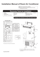
Installation Manual of Room Air Conditioner
No.0010518787
Read this manual before installation
1.Driver
2.Hacksaw
3.Hole core drill
4.Spanner(17,19 and 26mm)
5.Torque wrench(17mm,22mm,26mm)
6.Pipe cutter
7.Flaring tool
8.Knife
9.Nipper
12.Reamer
10.Gas leakage detector or
soap-and-water solution
11.Measuring tape
Explain sufficiently the operating means to the user
according to this manual.
A
B
C
D
E
F
G
Optional parts for piping
Mark
Parts name
Non-adhesive tape
Adhesive tape
Saddle(L.S) with screws
Connecting electric cable
for indoor and outdoor
Drain hose
Heating insulating material
Piping hole cover
Arrangement of piping directions
Rear left
Rear
right
Left
Below
Right
The marks from
to
in the figure are the parts numbers.
The distance between the indoor unit and the floor should be
more than 2m.
A
G
Attention must be paid to
the rising up of drain hose
m
c
5
n
a
h
t
e
r
o
m
m
c
0
1
n
a
h
t
e
r
o
m
m
c
0
1
n
a
h
t
e
r
o
m
A
C
No.
Accessory parts
Remote controller
R-03 dry battery
Mounting plate
Drain hose
Steel nail, cement
Screw
Plastic cap
Drain-elbow
Cover
Cushion
1
1
2
3
4
5
6
7
8
9
10
2
1
1
6
4
1
1
4
1
Number
of
articles
Accessory parts
4X50
4X25
Pipe supporting plate
11
Connecting cable
1
m
c
0
1
n
a
h
t
e
r
o
m
m
c
0
6
n
a
h
t
e
r
o
m
m
c
5
1
n
a
h
t
e
r
o
m
m
c
0
1
n
a
h
t
e
r
o
m
D
E
Note:Cooling only units don't have Drain-elbow
Drawing for the installation of indoor and outdoor units
Necessary Tools for Installation