Harman Kardon CP 15 Quick Start Guide
Harman Kardon CP 15 Manual
 |
View all Harman Kardon CP 15 manuals
Add to My Manuals
Save this manual to your list of manuals |
Harman Kardon CP 15 manual content summary:
- Harman Kardon CP 15 | Quick Start Guide - Page 1
you for purchasing a Harman Kardon CP 15 Home Theater System. This Quick-Start Guide will help you with a basic system installation. For detailed information on any step in this Guide, please refer to the pages referenced in the Owner's Manual for the AVR 135 that is part of this system. We strongly - Harman Kardon CP 15 | Quick Start Guide - Page 2
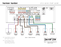
® CP 15 QUICK-START GUIDE 135 (100W, 1A MAX) (50W, 0.5A MAX) LINE IN/SUB/LFE SUBWOOFER + _ FRONT RIGHT SPEAKER Step 2. Connect the speakers to the receiver: red (+) on speaker to colored (+) on receiver and black (-) to black (-). (See page 12.) Step 3. Connect the Subwoofer Pre-Out jack to the - Harman Kardon CP 15 | Quick Start Guide - Page 3
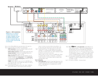
ON (see pages 13, 14-15). Step 6. Connect other source devices 5 on the back of this Guide. Plug all sources into an AC each video source device used in your system. Remember to switch the TV to subwoofer). Hold the remote steady until the process is completed (see page 2 of the RCP 2 owner's manual - Harman Kardon CP 15 | Quick Start Guide - Page 4
Optical Coax 135 A Harman International Company 250 Crossways Park Drive, Woodbury, New York 11797 www but connections may be made to best fit your system requirements. The Video 3 inputs are on the front whether digital audio is available for all channels. It may be necessary to make BOTH
-
 1
1 -
 2
2 -
 3
3 -
 4
4
 |
 |

Thank you for purchasing a Harman Kardon CP 15 Home Theater System.
This Quick-Start Guide will help you with a basic system installation. For detailed
information on any step in this Guide, please refer to the pages referenced in
the Owner’s Manual for the AVR 135 that is part of this system. We strongly
recommend that you read all three Owner’s Manuals for complete details on
how to install, configure and operate the AVR 135, DVD 22 and HKTS 8, as
well as for the important safety information they contain. You should also read
the Owner’s Manual for the included RCP 2 system remote.
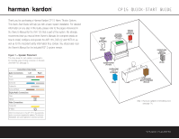
Figure 1 – Speaker Placement
The colors shown for each speaker correspond to
the matching output terminal connection on the back
of the AVR 135 (see page 7).
FRONT
LEFT
SPEAKER
(White)
SURROUND
BACK SPEAKER
(Brown)
CENTER
SPEAKER
(Green)
SUBWOOFER
(Purple)
SURROUND
LEFT
SPEAKER
(Blue)
FRONT
RIGHT
SPEAKER
(Red)
SURROUND
RIGHT
SPEAKER
(Gray)
Step 1. Place your speakers in the listening room
(see page 14).
SPEAKER PLACEMENT
CP15 QUICK-START GUIDE
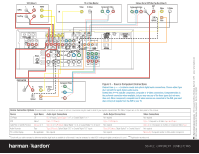
Connections Color Guide
Audio Connections
Left
Right
Front
Center
Surround
Subwoofer
Surround Back
Digital Audio Connections
Coax
Optical
Video Connections
Composite
S-Video
Match the colored jacks on the AVR 135 to the appropriate
jacks on your source equipment or speakers. The colors are
standardized, but not all equipment or connectors use them.
®