Harman Kardon TA12 Owners Manual
Harman Kardon TA12 Manual
 |
View all Harman Kardon TA12 manuals
Add to My Manuals
Save this manual to your list of manuals |
Harman Kardon TA12 manual content summary:
- Harman Kardon TA12 | Owners Manual - Page 1
SERVICE INSTRUCTIONS IMPORTANT It is essential you read this instruction book carefully before setting up your Harman-Kardon high Harman-Kardon first. We will suggest a warranty station in your area and give you the proper procedure and authorization for shipping. INSTALLATION Your Solo II receiver - Harman Kardon TA12 | Owners Manual - Page 2
section under Electrical Connections. ELECTRICAL CONNECTIONS AM Antenna: The Harman-Kardon ferrite loopstick built into the Solo II comprises all the quality. It is sometimes advisable to ground the phonograph chassis to the receiver in order to reduce hum and other unwanted noise. Attach a wire - Harman Kardon TA12 | Owners Manual - Page 3
) FM broadcasting, by its very nature, eliminates almost all natural and man-made static. However, the characteristics of FM which makes this possible also causes problems in tuning. The Solo II incorporates a special electronic circuit known as Automatic Frequency Control that overcomes these - Harman Kardon TA12 | Owners Manual - Page 4
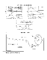
MC 300KC FM FM ANT. AC-VTVM TEST 90 MC OSC, RF, MAXIMUM 60 CPS TERMINAL OR SCOPE POINT MIXER COILS OUTPUT FM ALIGNMENT PROCEDURE HARMAN - KARDON, INC. - Harman Kardon TA12 | Owners Manual - Page 5
AMPLIFIER CHARACTERISTICS +12 +8 MAX. BASS BOOST MAX. TREBLE BOOST 18 IS 12 / . / 9 I e .16. ,....... • . FLAT RESPONSE Lu -4 8 -12 20 MAX. BASS CUT MAX TREBLE CUT 50 100 200 500 1000 2000 5000 10K 20K FREQUENCY IN CYCLES PER SECOND TONE CONTROL AND FREQUENCY RESPONSE - Harman Kardon TA12 | Owners Manual - Page 6
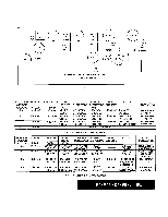
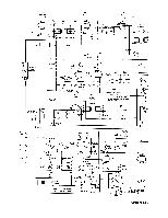
Vla ECC85 Inv C3 47 C4 C5 N750 .68 106 68 CI ^470 GL781543 COILS (2 ) VI b ECC 85 ICOV 6 R2 3.3M C6 I 106 T2 GT781993 v• 1: 1 5 - -T V2 6BA6 609 O ev T3 GT781994 LI .24uh E L2 3.3uh C24 2.2 C7 - 1019 R3 151( 10K 47 N5600 FM ANTENNA TERMINAL T C26 101( R20 226 C23 470 - Harman Kardon TA12 | Owners Manual - Page 7
270-1W 610% R61 1K V13 EL84 R62 220 7 312V GRN YEL RED/BLK 8LK T2 FTI712364 ER1712324 SPEAKER SELECTOR SWITCH harman kardon 1I7VAC 60CPS AC INTERLOCK RESISTANCE CHART TUBE 2 3 4 5 6 7 8 V1 ECC85 21K 0 68 0 0 35K 3.3M 0 0 V2 6BA6AFMM 3.OM 3.OM 0 0 0 0 0 EL5K 8.51( 0 0 25K 25K - Harman Kardon TA12 | Owners Manual - Page 8
V6 ECC85 V1 ECCB5 T2 V2 6BA6 T3 OSC INJECTION TEST POINT FEEDBACK V3 6AU6 These photographs show the printed circuit boards used in the Harman-Kardon Solo II and indicate to some degree the corn-, plexity of design and painstak-' ing care required in the plan- ning of such a unit. FM - Harman Kardon TA12 | Owners Manual - Page 9
many hours of listening enjoyment. Our Customer Service Department is maintained to answer your correspondence about High Fidelity and to make recommendation of appropriate companion accessories. Please feel free to write without obligation. harman kardon 520 MAIN STREET 8 WESTBURY. L. I.. N. Y. - Harman Kardon TA12 | Owners Manual - Page 10
harman kardon external antenna. Distortion: Less than 1% harmonic on FM. Less than 1% harmonic for up to 80% mod. on AM Mechanical Disassembly makes board easily available for service. Dimensions: 13-1/2 in. deep, , W/White Line Knob, Tuning Instruction Pamphlet Mounting Template Schematic . .
-
 1
1 -
 2
2 -
 3
3 -
 4
4 -
 5
5 -
 6
6 -
 7
7 -
8
-
9
-
10
 |
 |

harman
kardon
Model
TA
-12
11
HIGH
FIDELITY
TUNER
-AMPLIFIER
OPERATION
AND
SERVICE
INSTRUCTIONS
IMPORTANT
It
is
essential
you
read
this
instruction
book
care-
fully
before
setting
up
your
Harman-Kardon
high
fi
delity
system.
You
have
invested
in
a
fi
ne
instrument
into
which
many
excellent
engineering
developments
have
been
incorporated.
Each
is
important
for
the
proper
operation
of
your
system.
This
book
has
been
written
in
simple
nontechnical
language
and
if
you
will
take
the
time
to
read
it
fi
rst
before
doing
anything
else
you
will
fi
nd
it
simple
to
obtain
optimum
performance
from
your
new
Solo
II.
We
especially
call
your
attention
to
the
paragraph
describing
the
proper
adjustment
of
the
Hum
Bucking
Control.
This
control
should
be
adjusted
prior
to
per-
manent
installation
of
the
instrument.
UNPACKING
After
unpacking
the
Solo
II,
inspect
it
carefully
for
signs
of
damage
in
transit.
Your
unit
was
subjected
to
many
inspections
and
tests
prior
to
packing.
If
damage
is
visible,
notify
your
dealer
immediately.
If
the
unit
was
shipped
to
you,
notify
the
transportation
company
at
once.
...
the
folds
of
the
packing
material
before
discarding
it.
Your
package
should
contain:
1
Solo
II,
Model
TA
-12.
1
Instruction
Booklet.
1
Antenna
Wire.
(FM)
1
Warranty
Card.
1
Template
and
Cabinet
Installation
Instructions.
It
is
strongly
urged
that
the
warranty
card
be
com-
pleted
and
mailed
without
delay,
to
protect
your
rights
under
the
warranty.
If
you
shotild
require
repair
ser-
vice
or
information
on
the
use
of
the
Solo
II,
we
will
be
able
to
identify
your
unit
immediately,
and
respond
quickly,
NOTE:
To
expedite
iervice,
when
necessary,
please
contact
Harman-Kardon
fi
rst.
We
will
suggest
a
warranty
station
in
your
area
and
give
you
the
proper
procedure
and
authorization
for
shipping.
INSTALLATION
Your
Solo
II
receiver
may
be
installed
on
an
open
shelf,
table,
bookcase
or
high
fi
delity
equipment
cabinet.
For
cabinet
mounting,
refer
to
the
template
supplied
with
this
instruction
book.
Ventilation:
All
electrical
equipment
generates
heat
which
must
be
allowed
to
escape.
Although
the
Solo
II
is
well
Check
the
contents
of
the
carton
carefully.
Inspect