Hayward E-Command 4 Model: ALL MODELS Installation - Page 11
Low Voltage Wiring - communication error
 |
View all Hayward E-Command 4 manuals
Add to My Manuals
Save this manual to your list of manuals |
Page 11 highlights
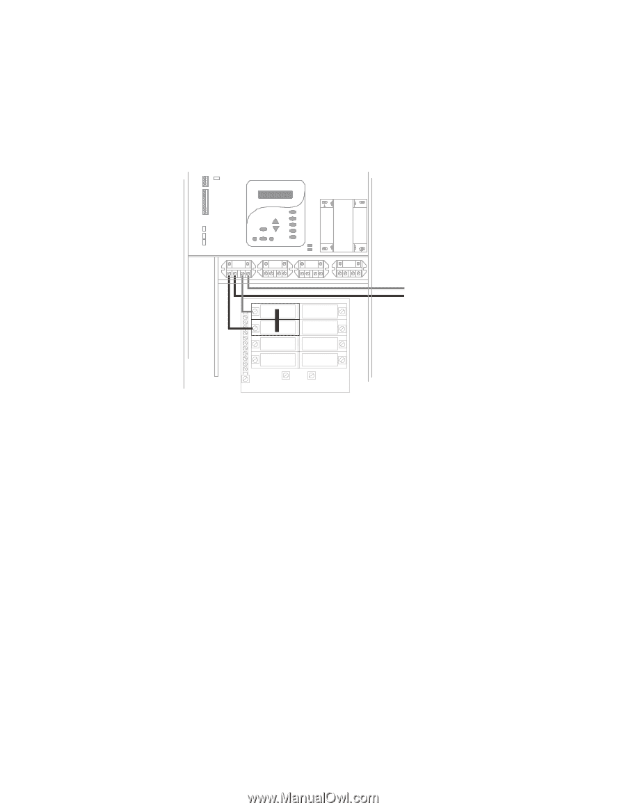
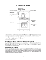
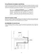
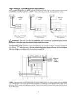
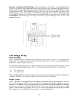
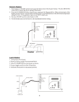
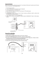
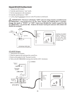
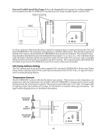
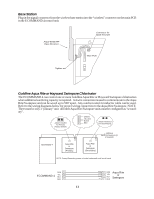
Hayward Variable Speed Filter Pump: Proper installation of the Hayward TriStar Variable Speed Control (VSC) includes high voltage input wiring, communication wiring, and menu configuration/settings. Refer to the following diagram for proper input wiring to the VSC. Wiring from the 220V breaker must connect through the ECOMMAND 4's Filter relay. The Filter relay is used to supply input power to the VSC pump control. The relay will be on when the filter pump output is on. When the filter pump output is off, the relay will be off. Note that when the filter pump relay is off (power off to the VSC), the ECOMMAND 4 will not display errors or diagnostics for the pump. The filter pump relay must be on for diagnostic function. 220 VAC input power to VSC Low Voltage Wiring Valve Actuators The ECOMMAND 4 can control up to three automatic valve actuators. Two of the valve outputs are dedicated to the pool/spa suction (Valve2) and return (Valve1) valves. Valve3 is for general purpose use (solar, water feature, in-floor cleaner, etc.). For installations with solar heating, Goldline offers the AQ-SOL-KIT-xx solar kit that contains a valve, actuator, and extra temperature sensor. The "xx" indicates the valve type from the 3 choices below: -1P 1.5" Positive Seal -2P 2" Positive Seal The ECOMMAND 4 is compatible with standard valve actuators manufactured by Hayward, Pentair/ Compool, and Jandy. See diagram on page 5 for the location of valve connectors. Heater Control The ECOMMAND 4 provides a set of low voltage dry contacts that can be connected to most gas heaters or heat pumps with 24V control circuits. Refer to the diagram on the following page for a generic connection. The manuals supplied with most heaters also include specific wiring instructions for connecting the heater to an external control (usually identified as "2-wire" remote control). For millivolt or line voltage heaters, contact Goldline Tech support, 908-355-7995. Refer to the diagrams and the information on the following pages for more details on the connection to several popular heaters. 8
-
 1
1 -
2
-
3
-
4
-
5
-
 6
6 -
 7
7 -
 8
8 -
 9
9 -
 10
10 -
 11
11 -
 12
12 -
 13
13 -
 14
14 -
 15
15 -
 16
16 -
17
-
18
-
19
-
20
-
21
-
22
-
23
-
24
-
25
-
26
-
27
-
28
-
29
-
30
-
31
-
32
 |
 |