Hayward E-Command 4 Model: ALL MODELS Installation - Page 13
Hayward Heaters, Pentair/Purex/MiniMax - board
 |
View all Hayward E-Command 4 manuals
Add to My Manuals
Save this manual to your list of manuals |
Page 13 highlights
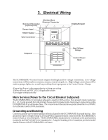
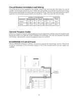
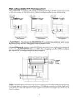
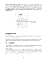
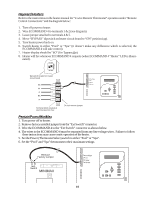
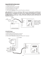
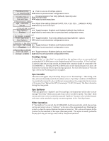
Hayward Heaters Refer to the instructions in the heater manual for "2-wire Remote Thermostat" operation under "Remote Control Connections" and the diagram below: 1. Turn off power to heater. 2. Wire ECOMMAND 4 to terminals 1 & 2 (see diagram). 3. Leave jumper attached to terminals 4 & 5. 4. Move "BYPASS" dipswitch on heater circuit board to "ON" position (up). 5. Turn heater power back on. 6. Switch heater to either "Pool" or "Spa" (it doesn't make any difference which is selected, the ECOMMAND 4 will take control). 7. Heater display should be "bO" (for "bypass On). 8. Heater will fire whenever ECOMMAND 4 requests (when ECOMMAND 4 "Heater" LED is illumi- nated). ºC ON ºF OFF Dipswitch located on heater circuit board PK W R BK R Pool/Spa Air Solar Heater Terminal block located at electrical junction box Do not remove jumper Pentair/Purex/MiniMax 1. Turn power off to heater. 2. Remove factory installed jumper from the "Ext Switch" connector. 3. Wire the ECOMMAND 4 to the "Ext Switch" connector as shown below. 4. The wires to the ECOMMAND 4 must be separated from any line voltage wires. Failure to follow these instructions may cause erratic operation of the heater. 5. Set the Power (Thermostat Select) switch to either "Pool" or "Spa". 6. Set the "Pool" and "Spa" thermostats to their maximum settings. Remove Factory Jumper Ext. Switch MINIMAX Pool/Spa Air Solar Heater 10
-
 1
1 -
2
-
3
-
4
-
5
-
6
-
7
-
 8
8 -
 9
9 -
 10
10 -
 11
11 -
 12
12 -
 13
13 -
 14
14 -
 15
15 -
 16
16 -
 17
17 -
 18
18 -
19
-
20
-
21
-
22
-
23
-
24
-
25
-
26
-
27
-
28
-
29
-
30
-
31
-
32
 |
 |