Hayward E-Command 4 Model: ALL MODELS Installation - Page 16
Base Station, Goldline Aqua Rite or Hayward Swimpure Chlorinator
 |
View all Hayward E-Command 4 manuals
Add to My Manuals
Save this manual to your list of manuals |
Page 16 highlights
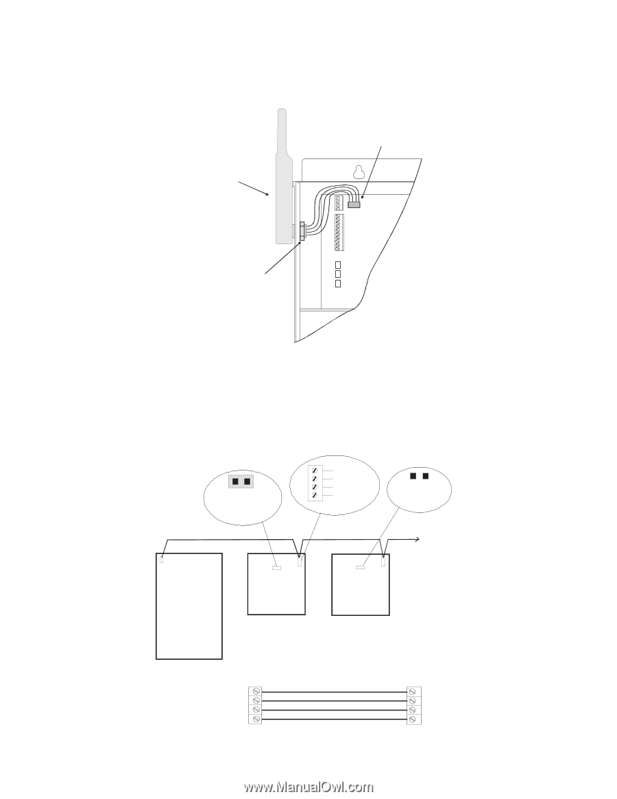
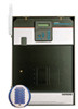
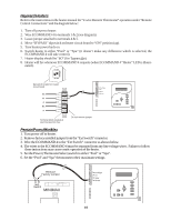
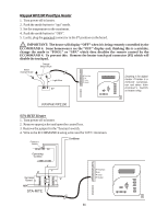
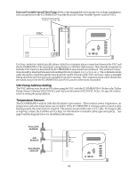
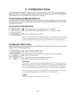
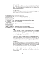
Base Station Plug in the pigtail connector from the wireless base station into the "wireless" connector on the main PCB in the ECOMMAND 4 control unit. AQL2-BASE-RF Base Receiver Connector for Base Receiver Main PCB Tighten nut Goldline Aqua Rite or Hayward Swimpure Chlorinator The ECOMMAND 4 can control one or more Goldline Aqua Rite or Hayward Swimpure chlorinators when additional sanitizing capacity is required. A 4 wire connection is used to communicate to the Aqua Rite/Swimpure and can be wired up to 500' apart. Any outdoor rated 4 conductor cable can be used. Refer to the wiring diagrams below for proper wiring connection to the Aqua Rite/Swimpure. NOTE: There must be only 1 "primary" unit. All other Aqua Rite/Swimpure units must be configured as "secondary". Jumper Installed For Primary (Factory Default) 4 GREEN 3 YELLOW 2 BLACK 1 RED Jumper Removed For Secondary(s) Additional Aqua Rite/Swimpure(s) (if required) Ecommand 4 Aqua Rite or Swimpure (Primary) Aqua Rite or Swimpure (Secondary) NOTE: Primary/Secondary jumper is located underneath small circuit board. ECOMMAND 4 GRN 4 YEL 3 BLK 2 RED 1 13 green 4 GRN Aqua Rite yellow 3 YEL or black red 2 BLK Swimpure 1 RED
-
 1
1 -
2
-
3
-
4
-
5
-
6
-
7
-
8
-
9
-
10
-
 11
11 -
 12
12 -
 13
13 -
 14
14 -
 15
15 -
 16
16 -
 17
17 -
 18
18 -
 19
19 -
 20
20 -
 21
21 -
22
-
23
-
24
-
25
-
26
-
27
-
28
-
29
-
30
-
31
-
32
 |
 |