Hayward Micro Star-Clear C2001540LS Micro Star Clear Filters
Hayward Micro Star-Clear Manual
 |
View all Hayward Micro Star-Clear manuals
Add to My Manuals
Save this manual to your list of manuals |
Hayward Micro Star-Clear manual content summary:
- Hayward Micro Star-Clear | C2001540LS Micro Star Clear Filters - Page 1
OWNER'S GUIDE IS2001540LS-99 MODEL C2001540LS SERIES Your Micro Star-Clear cartridge filter has an output rating of 1400 gallons (5299 L) per hour. The filter and pump are combined on a molded mounting base and are manufactured from durable, corrosion-proof materials. The system is designed for - Hayward Micro Star-Clear | C2001540LS Micro Star Clear Filters - Page 2
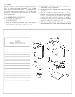
and clean. Or, replace with clean, spare cartridge. (See Cleaning Cartridge) PARTS Model C2001540LS REF. NO PART NO. DESCRIPTION 1 CX120AA Filter Head 2 CX120D O-Ring 3 CX200RE Cartridge Element 20 sq. ft. 4 CX120B Filter Body Housing 5 ECX1321A Air Relief Valve with O-Ring 6 SPX1485C - Hayward Micro Star-Clear | C2001540LS Micro Star Clear Filters - Page 3
. Reinstall cartridge in filter tank. Tighten cover only a few turns when storing. SERVICE & REPAIRS Consult your local and authorized Hayward dealer or service center. No returns may be made directly to the factory without the expressed written authorization of Hayward Pool Products, Inc. ALGAE - Hayward Micro Star-Clear | C2001540LS Micro Star Clear Filters - Page 4
Rev. 4/99 A © 1999 Hayward Printed in U.S.A.
-
 1
1 -
 2
2 -
 3
3 -
 4
4
 |
 |
IS2001540LS-99
OWNER’S GUIDE
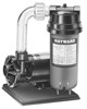
Your Micro Star-Clear cartridge filter has an output rating of 1400 gallons (5299 L) per hour.
The filter and pump are combined on a molded mounting base and are manufactured from
durable, corrosion-proof materials. The system is designed for installation below the pool
water line.
The Micro Star-Clear filter system utilizes a reusable single element, reinforced polyester
filter cartridge to provide a high degree of water clarity with absolute minimum care.
Removal of the cartridge for routine cleaning is fast and easy to do.
The SP1540 series Power-Flo LX
pump is a non-corrosive centrifugal pump with pressure,
flow and operation designed for swimming pool service and may be operated on an inter-
mittent or continuous basis.
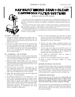
SYSTEM
LOCATION
Though the system is designed for outdoor use, it is
advisable to protect electrical components from the
weather. Select a well-drained area, one that will not
flood when it rains.
Position the system below the swimming pool water
line and as close to the pool as possible. Set the
mounting platform level. Allow a minimum clearance
for cartridge removal. Be sure the pipe connections,
drain, etc., are accessible for convenient operation
and cartridge removal.
TO
ASSEMBLE
THE
SYSTEM
Place pump and motor on mounting base. Align holes
in motor base with holes in mounting base and secure
with two screws and washers provided.
Securely thread sweep elbow, with 3-4 wraps of
Teflon pipe tape, into outlet of pump. Position so that
large thread end points back toward the motor, at an
angle, toward corner of base.
Thread the ball end of union, with union nut, into
filter connection marked “IN.”
Use Teflon tape (3-4
wraps on thread) and screw in as far as possible hand
tight, then one additional turn with a wrench.
Adjust ball and socket and join by hand tightening
union nut.
Do not overtighten.
All plumbing connections on the system are 1-1/2”
N.P.T.
When making connections, use plastic male-
end adapters and flexible hose. Apply
three turns of
Teflon tape or plastic pipe sealant to the male
threads. Screw the fitting into the thread hand tight;
then using a wrench, tighten one more full turn.
Additional tightening is unnecessary and could
result in damage to components.
NOTE: For extra convenience, you may wish to install
valves on the inlet and discharge of the system to
prevent back flow of water when removing cartridge.
See dealer for further information.
Connect the pool suction plumbing between the
skimmer pool outlet, and the pump. Connect the pool
return (inlet) plumbing.
A drain plug is furnished with each filter and is all
that is needed for complete filter draining. A manual
air vent valve is furnished to aid in bleeding off
unwanted air when starting the filter.
All electrical connections must be made in
accordance with local codes.
Check for joint leaks before operating the system.
Refer to pump instruction booklet for pump
information.
BEFORE STARTING THE FILTER
Superchlorinate the pool water by adding unstabilized
granular or liquid chlorine. Stabilized forms of chlorine
are recommended for normal daily use after the initial
clean up of the water.
Follow chemical manufacturer’s
recommendations for superchlorination and daily use.
STARTING THE FILTER
Open manual air vent valve a few turns.
CAUTION: All
suction and discharge valves must be open when
starting the system. Failure to do so could cause
severe personal injury and/or property damage.
Prime and start the pump following the manufacturer’s
instructions. Air trapped in the system will automatically
vent to the pool and out vent valve.
Close vent valve as
soon as air is vented.
1.
2.
1.
2.
3.
4.
5.
6.
7.
8.
9.
10.
MODEL C2001540LS SERIES