HealthRider 230 English Manual
HealthRider 230 Manual
 |
View all HealthRider 230 manuals
Add to My Manuals
Save this manual to your list of manuals |
HealthRider 230 manual content summary:
- HealthRider 230 | English Manual - Page 1
hot line will provide immediate assistance, free of charge to you. CUSTOMER HOT LINE: 1-800-999-3756 Mon.ÐFri., 6 a.m.Ð6 p.m. MST CAUTION Read all precautions and instructions in this manual before using this equipment. Save this - HealthRider 230 | English Manual - Page 2
20 Weight Resistance Chart 22 Trouble-shooting and Maintenance 23 Ordering informed of all precautions. 2. Read all instructions in this manual and in the accompanying literature before using the persons with pre-existing health problems. Read all instructions before using. ICON assumes no - HealthRider 230 | English Manual - Page 3
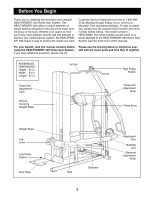
improve your cardiovascular system, the HEALTHRIDER¨ 230 makes it easy to achieve the results you want. Customer Service Department toll-free at 1- HEALTHRIDER¨ 230 Home Gym System (see the front cover of this manual). For your benefit, read this manual carefully before using the HEALTHRIDER¨ 230 - HealthRider 230 | English Manual - Page 4
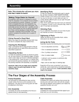
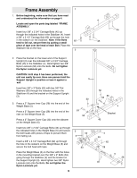
have included a PART IDENTIFICATION CHART located in the center of this manual. Place the chart on the floor or work table and use Parts Tighten all parts as you assemble them, unless instructed to do otherwise. Lining Up the Tools Assembly requires the support your body while you are exercising. 4 - HealthRider 230 | English Manual - Page 5
Do not tighten the Nylon Locknuts yet. CAUTION: Until step 3 has been performed, the unit can easily tip over. Have one person hold the Support Upright in position or lean it against a wall. Insert two 3/8Ó x 3Ó Bolts (53) with two 3/8Ó Flat Washers (55) through the indicated holes in the Stabilizer - HealthRider 230 | English Manual - Page 6
4. Place the bracket on the lower end of the Main 4 Upright (1) over the indicated 3/8Ó x 2 3/4Ó Carriage Bolts (45) in the Stabilizer (4). Hand tighten two 3/8Ó Nylon Locknuts (50) onto the Bolts. Do not tighten the Nylon Locknuts yet. Insert two 3/8Ó x 3Ó Bolts (53) with two 3/8Ó Flat - HealthRider 230 | English Manual - Page 7
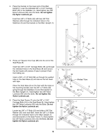
55 8. Slide a 3/8Ó Flat Washer (55) onto a 3/8Ó x 4 3/4Ó Bolt (46) and push the Bolt through the Top Frame (9). Push the Bolt into the hole in the Support Upright (3) until the tip of the Bolt is visible inside the Upright. Slide the 1/2Ó x 1 13/16Ó Bushing (84) down into the Upright and push - HealthRider 230 | English Manual - Page 8
each Weight (21). Make sure the large pin groove is pointed downward, as shown. Slide all of the included Weights (21) onto the two Weight Guides (15). Make sure the Weights are oriented correctly. The adjustment holes must be turned towards the center of the unit, as shown. For packaging purposes - HealthRider 230 | English Manual - Page 9
Arm Assembly 13 13. Press Arm AssemblyÑLocate and open the parts bag labeled ÒARM ASSEMBLY.Ó 8 58 Press a 2Ó Square Inner Cap (28) into the open end of each press arm on the Press Frame (8). Press a 1Ó Round Inner Cap (58) into each of the indicated holes on the press arms. Locate the Press - HealthRider 230 | English Manual - Page 10
17. Leg Lever Assembly. Attach a Bumper (40) to the 17 Seat Frame (7) with a #8 x 1Ó Screw (78). 7 Press a 2Ó Square Inner Cap (28) into the indicated end of the Leg Lever (41). Lubricate a 3/8Ó x 3Ó Bolt (53). Attach the Leg Lever (41) to the Seat Frame (7) with the 3/8Ó x 3Ó Bolt and a 3/8Ó - HealthRider 230 | English Manual - Page 11
91 21. Route the Low Cable (72) through the indicated slot in the Support Upright (3) from above. Locate the Small Pulley Frame (22) and remove both of as shown. Route the Low Cable (72) through the indicated slot in the Support Upright (3) from below. 21 Route Cable Through Slot From Above 72 3 - HealthRider 230 | English Manual - Page 12
24. Thread the bolt at the end of the Low Cable (72) a 24 couple of turns into the Weight Tube (17). 72 Bolt 17 25. Identify the High Cable (73). It is approximately 340Ó long and it has a ball on one end and a loop on the other. Route the end of the High Cable (73) with the loop through the - HealthRider 230 | English Manual - Page 13
28. Wrap the High Cable (73) around a 3 1/2Ó Pulley (24) 28 in the direction shown and route it back down through the bracket on the Main Upright (1). Attach the 3 1/2Ó Pulley (24) inside the bracket on the Main Upright (1) with the 3/8Ó x 3Ó Bolt (53) that was 73 inserted in step 26. Secure the - HealthRider 230 | English Manual - Page 14
32. Wrap the High Cable (73) around a 3 1/2Ó Pulley (24) 32 50 in the direction shown. Attach the 3 1/2Ó Pulley (24) to the lower half of the Small Pulley Frame (22) with a 3/8Ó x 2Ó Bolt (54) and 24 a 3/8Ó Nylon Locknut (50). 73 22 54 33. Wrap the High Cable (73) around a 3 1/2Ó Pulley (24) - HealthRider 230 | English Manual - Page 15
36. Route the High Cable (73) through the slot in the leg 36 of the Seat Frame (7). 7 41 Attach the closed loop at the end of the High Cable (73) to the Leg Lever (41) with a 3/8Ó x 2 3/4Ó Bolt 47 (47), two 3/8Ó Flat Washers (55) and a 3/8Ó Nylon Locknut (50). Note: Do not overtighten the - HealthRider 230 | English Manual - Page 16
40. Important: Follow all three Cables from end to 40 end and make sure they rest in the grooves of all Pulleys and that both the Cables and the Pulleys move smoothly. Attach the bolt at the end of the Low Cable (72), the 1/2Ó Plain Nut (68), the 1 1/2Ó Flat Washer (48) and the Adjustment Tube - HealthRider 230 | English Manual - Page 17
44. Press two 3/4Ó Round Inner Caps (43) into each Pad Tube (42). Insert one Pad Tube (42) into the Seat Frame (7). Slide a Foam Roller (30) onto each end of the Pad Tube. Insert the other Pad Tube (42) into the Leg Lever (41). Slide a Foam Roller (30) onto each end of the Pad Tube. 44 30 43 30 - HealthRider 230 | English Manual - Page 18
remaining parts will be explained in ADJUSTMENT, beginning on page 20 of this manual. Before using the home gym system, pull each cable a few times to If one of the cables does not move smoothly, find and correct the problem. IMPORTANT: If the cables are not properly installed, they may be damaged - HealthRider 230 | English Manual - Page 19
Cable Diagram The Cable Diagrams below show the proper routing of the Butterfly Cable (92), the High Cable (73) and the Low Cable (72). The numbers show the correct route for each Cable. Make sure the Cables are routed correctly, that the Pulleys move smoothly and that the Cable Traps do not touch - HealthRider 230 | English Manual - Page 20
Adjustment The instructions below describe how each part of the home gym system can be adjusted. Refer to the exercise guide accompanying this manual to see how the home gym system should be set up for each exercise. IMPORTANT: When attaching the lat bar or ab strap, make sure - HealthRider 230 | English Manual - Page 21
Adjusting the Press Arms Pull out on the Press Frame Knob (11) on the Press Frame (8) and pivot the press arms up or down to the 14 8 desired position. Release the Press Frame Knob and let it snap into one of the adjustment holes in the cam on the Press Arm Adjustment Frame (14). Cam Note: - HealthRider 230 | English Manual - Page 22
The actual resistance at each station may vary due to differences in individual weight plates as well as friction between the cables, pulleys, and weight guides. This chart shows the resistance for the five extra weight plates included with the Weight Expansion Set (see No. 16-20 below). The set is - HealthRider 230 | English Manual - Page 23
Trouble-shooting and Maintenance Inspect Weight (21), counting from the top. See ÒChanging the Weight SettingÓ on page 20 for instructions on moving the Weight Pin. Loosen the 1/2Ó Plain Nut (68) securing the bolt at the end back cover of this manual. Adjustment Holes 54 25 72 Bolt 68 17 21 23 - HealthRider 230 | English Manual - Page 24
3/4Ó Retainer Ring (31) 3/4" Round Inner Cap (43) 1Ó Retainer Ring (32) 1" Round Inner Cap (58) 5/8Ó x 1/2Ó Bushing (85) 5/8Ó x 1Ó Bushing (86) 5/8Ó x 1 1/4Ó Bushing (91) 1" Round Cover Cap (81) 3/4Ó Dome Cap (82) 1/2Ó x 3/8Ó Bushing (83) 1/2Ó x 3/4Ó Bushing (76) 1Ó x 1 1/2" Inner Cap (96) - HealthRider 230 | English Manual - Page 25
Part Identification Chart - Model No. HRSY23080 1 1/2" Flat Washer (48) 3/8" Flat Washer (55) 1/4" Flat Washer (71) 5/16" Nylon Locknut (64) 1/2" Plain Nut (68) 1/4" Nylon Jamnut (94) 3/8" Nylon Jamnut (63) 3/8" Nylon Locknut (50) #8 x 1Ó Screw (78) 1/4" x 3/4" Bolt (49) 1/4" x 1 1/2" Bolt - HealthRider 230 | English Manual - Page 26
3/8" x 6 1/2" Bolt (65) 3/8" x 1 3/4" Bolt (57) 3/8" x 2" Bolt (54) 3/8" x 2 3/4" Bolt (47) 3/8" x 2 3/4" Carriage Bolt (45) 3/8" x 3" Bolt (53) 3/8" x 3 1/2" Bolt (56) 3/8" x 3 1/2" Carriage Bolt (62) 3/8" x 3 3/4" Bolt (59) 3/8" x 4 3/4" Bolt (46) - HealthRider 230 | English Manual - Page 27
Leg Lever Bushing 5/8Ó x 1 1/4Ó Bushing Butterfly Cable Weight Support Plate 1/4Ó Nylon Jamnut 1/4Ó x 1 1/2Ó Bolt 1Ó x 1 1/2Ó Inner Cap 1 1/2Ó x 2Ó Inner Cap 1 1/4Ó Inner Cap Ankle Strap Allen Wrench Right Backrest Frame UserÕs Manual Exercise Guide Decal Sheet Note: Ò#Ó indicates a non-illustrated - HealthRider 230 | English Manual - Page 28
24 54 50 24 50 54 24 57 77 50 24 53 55 59 9 50 55 86 70 81 44 32 34 8 25 50 23 28 54 25 24 55 50 55 50 47 50 82 88 55 82 84 31 27 92 26 88 31 88 64 50 55 83 64 87 83 88 55 97 55 86 50 88 24 73 28 66 1 88 82 31 97 10 81 55 24 85 55 55 46 32 44 28 47 85 - HealthRider 230 | English Manual - Page 29
The NAME of the product (HEALTHRIDER¨ 230 Home Gym System). 3. The SERIAL NUMBER of the product (see the front cover of this manual). 4. The KEY NUMBER and or abnormal usage or repairs not provided by an ICON authorized service center, products used for commercial or rental purposes, or products
-
 1
1 -
 2
2 -
 3
3 -
 4
4 -
 5
5 -
 6
6 -
 7
7 -
8
-
9
-
10
-
11
-
12
-
13
-
14
-
15
-
16
-
17
-
18
-
19
-
20
-
21
-
22
-
23
-
24
-
25
-
26
-
27
-
28
-
29
 |
 |
¤
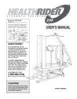
USER°S MANUAL
Model No. HRSY23080
Serial No.
The serial number is found in the
location shown below. Write the
serial number in the space above.
CAUTION
Read all precautions and instruc-
tions in this manual before using
this equipment. Save this manu-
al for future reference.
Serial
Number
Decal
PATENT PENDING
QUESTIONS?
As a manufacturer, we are
committed to providing complete
customer satisfaction. If you
have questions, or if there are
missing or damaged parts, we
will guarantee complete satisfac-
tion through direct assistance
from our factory.
TO AVOID UNNECESSARY
DELAYS, PLEASE CALL DIRECT
TO OUR TOLL-FREE CUSTOMER
HOT LINE. The trained techni-
cians on our customer hot line
will provide immediate assis-
tance, free of charge to you.
CUSTOMER HOT LINE:
1-800-999-3756
Mon.—Fri., 6 a.m.—6 p.m. MST