HealthRider Aire Strider E60 Elliptical English Manual - Page 6
Patch Screw 76 as shown. Tighten the Patch Screw
 |
View all HealthRider Aire Strider E60 Elliptical manuals
Add to My Manuals
Save this manual to your list of manuals |
Page 6 highlights
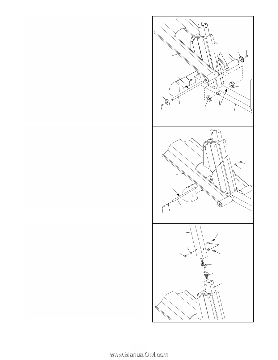
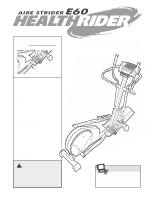
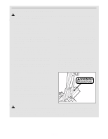
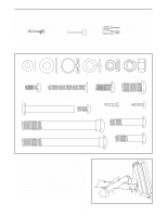
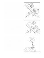
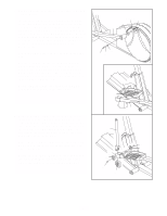
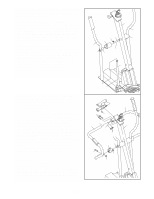
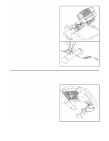
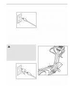
2. Identify the Pivot Axle (14), which is the longest axle. Slide a Ramp Cover (48) onto an M6 x 16mm Patch Screw (76) as shown. Tighten the Patch Screw into one end of the Pivot Axle. Apply a small amount of the included grease to the Pivot Axle. Have a second person hold the two Ramp Spacers (99) against the sides of the Frame (1) so they cover the indicated tubes on the Frame. Align the round tubes on the Ramp (3) with the Ramp Spacers; make sure that the Ramp is turned as shown in drawing 3 below. Insert the Pivot Axle (14) into the Ramp, the Ramp Spacers, and the Frame. If necessary, tap the Pivot Axle with a rubber mallet to insert it. Slide the other Ramp Cover (48) onto an M6 x 16mm Patch Screw (76) as shown. Tighten the Patch Screw into the open end of the Pivot Axle (14). 3. Slide an M6 Washer (64) onto an M6 x 16mm Patch Screw (76). Tighten the Patch Screw into one end of the Incline Axle (13). Apply a small amount of grease to the Incline Axle. Raise the Ramp (3). Insert the Incline Axle (13) into the welded tube under one side of the Ramp, through the motor screw, and then into the welded tube under the other side of the Ramp. As you insert the Incline Axle through the motor screw, make sure that the motor screw does not turn. Slide an M6 Washer (64) onto an M6 x 16mm Patch Screw (76). Tighten the Patch Screw into the open end of the Incline Axle (13). 4. Have another person hold the Upright (2) in the position shown. Make sure that the Upright is turned as shown in drawing 7 on page 8. Connect the Upper Wire Harness (95) to the Lower Wire Harness (42). Carefully pull the upper end of the Upper Wire Harness to remove the slack from the Wire Harnesses. Slide the Upright (2) onto the Frame (1). Be careful to avoid disconnecting or pinching the Wire Harnesses. Attach the Upright with three M10 x 25mm Button Screws (114) and three M10 Split Washers (57). 2 3 Grease 48 14 76 3 3 Grease 13 76 64 4 2 57 114 Tubes 48 76 99 99 Tubes 1 Motor Screw 76 64 114 57 114 95 42 1 6
-
 1
1 -
 2
2 -
 3
3 -
 4
4 -
 5
5 -
 6
6 -
 7
7 -
 8
8 -
 9
9 -
 10
10 -
 11
11 -
 12
12 -
13
-
14
-
15
-
16
-
17
-
18
-
19
-
20
-
21
-
22
-
23
-
24
-
25
-
26
-
27
-
28
 |
 |