HP 1050c Service Manual - Page 232
Left and Right Rear Covers
 |
View all HP 1050c manuals
Add to My Manuals
Save this manual to your list of manuals |
Page 232 highlights
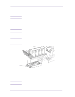
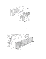
Removal and Installation Left and Right Rear Covers Refer to Figure 22. WARNING NOTE Removal Switch off the printer and remove the power cord. Working from the rear of the Printer. 1. Remove the T-10 Screw (Item 1) that attaches the left hand rear cover (Item 2) to the Printer. 2. Release the left hand rear cover (Item 2) from the retaining clip (item 3) that attaches the ferrite (item 4) to the rear cover. 3. Remove the T-10 Screw (Item 5) that attaches the right hand rear cover (Item 6) to the Printer. 4. Release the right hand rear cover (Item 6) from the retaining clip. 3 4 6 5 2 1 Figure 22: Left and Right Rear Covers 8-24 HP DesignJets 1050C and 1055CM Printers Service Manual
-
 1
1 -
2
-
3
-
4
-
5
-
6
-
7
-
8
-
9
-
10
-
11
-
12
-
13
-
14
-
15
-
16
-
17
-
18
-
19
-
20
-
21
-
22
-
23
-
24
-
25
-
26
-
27
-
28
-
29
-
30
-
31
-
32
-
33
-
34
-
35
-
36
-
37
-
38
-
39
-
40
-
41
-
42
-
43
-
44
-
45
-
46
-
47
-
48
-
49
-
50
-
51
-
52
-
53
-
54
-
55
-
56
-
57
-
58
-
59
-
60
-
61
-
62
-
63
-
64
-
65
-
66
-
67
-
68
-
69
-
70
-
71
-
72
-
73
-
74
-
75
-
76
-
77
-
78
-
79
-
80
-
81
-
82
-
83
-
84
-
85
-
86
-
87
-
88
-
89
-
90
-
91
-
92
-
93
-
94
-
95
-
96
-
97
-
98
-
99
-
100
-
101
-
102
-
103
-
104
-
105
-
106
-
107
-
108
-
109
-
110
-
111
-
112
-
113
-
114
-
115
-
116
-
117
-
118
-
119
-
120
-
121
-
122
-
123
-
124
-
125
-
126
-
127
-
128
-
129
-
130
-
131
-
132
-
133
-
134
-
135
-
136
-
137
-
138
-
139
-
140
-
141
-
142
-
143
-
144
-
145
-
146
-
147
-
148
-
149
-
150
-
151
-
152
-
153
-
154
-
155
-
156
-
157
-
158
-
159
-
160
-
161
-
162
-
163
-
164
-
165
-
166
-
167
-
168
-
169
-
170
-
171
-
172
-
173
-
174
-
175
-
176
-
177
-
178
-
179
-
180
-
181
-
182
-
183
-
184
-
185
-
186
-
187
-
188
-
189
-
190
-
191
-
192
-
193
-
194
-
195
-
196
-
197
-
198
-
199
-
200
-
201
-
202
-
203
-
204
-
205
-
206
-
207
-
208
-
209
-
210
-
211
-
212
-
213
-
214
-
215
-
216
-
217
-
218
-
219
-
220
-
221
-
222
-
223
-
224
-
225
-
226
-
 227
227 -
 228
228 -
 229
229 -
 230
230 -
 231
231 -
 232
232 -
 233
233 -
 234
234 -
 235
235 -
 236
236 -
 237
237 -
238
-
239
-
240
-
241
-
242
-
243
-
244
-
245
-
246
-
247
-
248
-
249
-
250
-
251
-
252
-
253
-
254
-
255
-
256
-
257
-
258
-
259
-
260
-
261
-
262
-
263
-
264
-
265
-
266
-
267
-
268
-
269
-
270
-
271
-
272
-
273
-
274
-
275
-
276
-
277
-
278
-
279
-
280
-
281
-
282
-
283
-
284
-
285
-
286
-
287
-
288
-
289
-
290
-
291
-
292
-
293
-
294
-
295
-
296
-
297
-
298
-
299
-
300
-
301
-
302
-
303
-
304
-
305
-
306
-
307
-
308
-
309
-
310
-
311
-
312
-
313
-
314
-
315
-
316
-
317
-
318
-
319
-
320
-
321
-
322
 |
 |
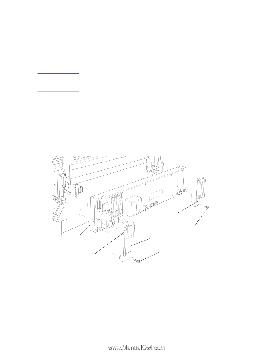
Removal and Installation
8-24
HP DesignJets 1050C and 1055CM Printers Service Manual
Left and Right Rear Covers
Refer to Figure 22.
Removal
WARNING
Switch off the printer and remove the power cord.
NOTE
Working from the rear of the Printer.
1.
Remove the T-10 Screw (Item 1) that attaches the left hand rear
cover (Item 2) to the Printer.
2.
Release the left hand rear cover (Item 2) from the retaining clip
(item 3) that attaches the ferrite (item 4) to the rear cover.
3.
Remove the T-10 Screw (Item 5) that attaches the right hand rear
cover (Item 6) to the Printer.
4.
Release the right hand rear cover (Item 6) from the retaining clip.
Figure 22: Left and Right Rear Covers
6
5
1
2
3
4