HP 2000sa HP StorageWorks 2000 Modular Smart Array racking instructions (49415
HP 2000sa Manual
 |
View all HP 2000sa manuals
Add to My Manuals
Save this manual to your list of manuals |
HP 2000sa manual content summary:
- HP 2000sa | HP StorageWorks 2000 Modular Smart Array racking instructions (49415 - Page 1
HP StorageWorks 2000 Modular Smart Array racking instructions Audience assumptions This document is for the person who installs, administers, and troubleshoots servers and storage systems. HP assumes that you are qualified in the servicing and installation of computer equipment and are trained in - HP 2000sa | HP StorageWorks 2000 Modular Smart Array racking instructions (49415 - Page 2
CAUTION: Lifting and positioning a disk array enclosure requires two people. HP StorageWorks MSA2000 series of user guides • The HP website: http://www.hp.com • Your nearest HP authorized reseller (locations and telephone numbers of these resellers are given on the HP website) • HP technical support
-
 1
1 -
 2
2
 |
 |
HP StorageWorks
2000 Modular Smart Array
racking instructions
© Copyright 2009 Hewlett-Packard Development Company, L.P.
First edition: January 2009
The information in this document is subject to change without notice.
Printed in China
www.hp.com
494159-002
Audience assumptions
This document is for the person who installs, administers, and
troubleshoots servers and storage systems. HP assumes that you are
qualified in the servicing and installation of computer equipment and are
trained in recognizing hazards in products and hazardous energy levels.
Rack planning and resources
The HP StorageWorks 2000 Modular Smart Array (MSA2000) supports
the HP 10000 series of racks. For information about setting up the rack,
including the appropriate warnings and cautions, see the documentation
that came with the rack. Updated rack information can be downloaded
from the HP website
h
t
tp://w
w
w
.hp
.co
m/pr
odu
c
ts/r
ac
ks
.
NOTE:
Other racks might also be suitable, but have not been tested.
Site requirements
Detailed site requirements are provided at the end of this document and
in the user guide. Before installing, verify that the installation site meets
the system requirements for:
•
space and airflow
•
temperature
•
power and grounding
Contents
Quantity
Description
2
Rear rail brackets
2
Front rail brackets
2
Side brackets
10
Cage nuts
6
Hanger pins*
4
8-32 x 3/16 Phillips flat-head screws
3
6-32 x 1/4 Phillips pan-head screws
6
8-32 x 3/8 Phillips flat-head screws
8
10-32 x 3/4 Phillips truss-head screws
2
10-32 x 5/8 Phillips flat-head screws
* Hanger pins may be preinstalled on the front and rear rail brackets.
Rack installation
HP recommends installing all enclosures at the bottom of the rack. To
optimize cabling access, avoid interleaving the enclosure and server
products.
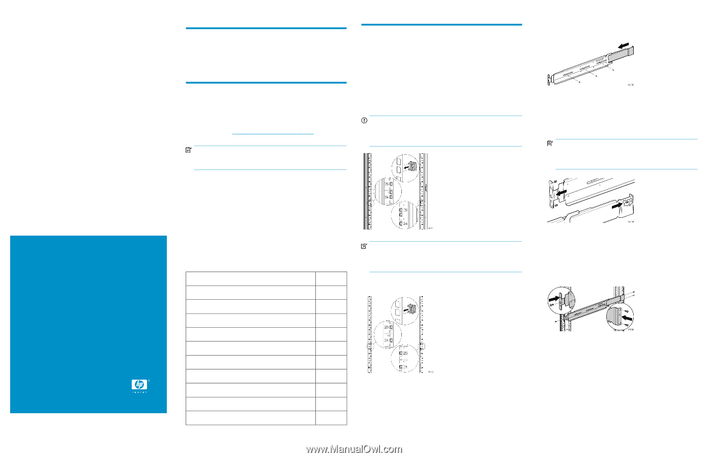
Step 1: Install cage nuts
Front
IMPORTANT:
The placement of the middle cage nut is different on the right
and left side on the front of the rack.
NOTE:
The markings shown are provided for illustration purposes only;
your device may be installed in a different location.
Rear
Step 2: Assemble rails
1.
Slide the rear rails into the front rails.
2.
Align the first, third, and fifth holes in the rear rail bracket with the
slots of the front bracket. Loosely install three 8-32 x 3/8 Phillips
flat-head screws in each rail set. They will be tightened after rails
are installed.
3.
Install two hanger pins into the front and one into the rear of each
rail set.
NOTE:
If the hanger pins are pre-installed in the rail sets, move
ahead to
Step 3: Install rails on the rack
.
Step 3: Install rails on the rack
1.
Use the hanger pins to hang the rails on the rack. The rails are
labeled
Left
and
Right
to indicate their position in the rack when
viewed from the front.
•
Front — Align the middle screw hole with the middle cage nut.
•
Rear — Align the two screw holes with the cage nuts.
2.
Secure the front of each rail to the rack with one 10-32 x 5/8 Phillips
flat-head screw (middle hole).
3.
Secure the rear of each rail to the rack with two 10-32 x 3/4 Phillips
truss-head screws.
4.
Tighten the screws holding the front and rear rail brackets together.
Step 4: Prepare enclosure
Attach one side bracket to each side of the enclosure as shown, using
8-32 x 3/16 Phillips flat-head screws.