HP 2000z-100 HP 2000 Notebook PC - Maintenance and Service Guide
HP 2000z-100 Manual
 |
View all HP 2000z-100 manuals
Add to My Manuals
Save this manual to your list of manuals |
HP 2000z-100 manual content summary:
- HP 2000z-100 | HP 2000 Notebook PC - Maintenance and Service Guide - Page 1
HP 2000 Notebook PC Maintenance and Service Guide - HP 2000z-100 | HP 2000 Notebook PC - Maintenance and Service Guide - Page 2
to change without notice. The only warranties for HP products and services are set forth in the express warranty statements accompanying such products and services. Nothing herein should be construed as constituting an additional warranty. HP shall not be liable for technical or editorial errors - HP 2000z-100 | HP 2000 Notebook PC - Maintenance and Service Guide - Page 3
Safety warning notice WARNING! To reduce the possibility of heat-related injuries or of overheating the device, do not place the device directly on your lap or obstruct the device air vents. Use the device only on a hard, flat surface. Do not allow another hard surface, such as an adjoining optional - HP 2000z-100 | HP 2000 Notebook PC - Maintenance and Service Guide - Page 4
iv Safety warning notice - HP 2000z-100 | HP 2000 Notebook PC - Maintenance and Service Guide - Page 5
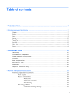
Display ...7 Button ...8 Keys ...9 Lights ...10 TouchPad ...11 Left side ...12 Right side ...13 Bottom ...14 3 Illustrated parts catalog ...15 Service tag ...15 Computer major components ...17 Display assembly subcomponents ...22 Cable Kit ...23 Mass storage devices ...24 Miscellaneous parts ...25 - HP 2000z-100 | HP 2000 Notebook PC - Maintenance and Service Guide - Page 6
Packaging and transporting guidelines 36 Component replacement procedures 38 Service tag ...38 Computer feet ...39 Battery ...39 Optical drive (select models only 40 WLAN module ...43 Memory module ...45 Hard drive ...46 Keyboard ...49 Top - HP 2000z-100 | HP 2000 Notebook PC - Maintenance and Service Guide - Page 7
Using Windows system restore points 95 When to create restore points 95 Create a system restore point 96 Restore to a previous date and time 96 8 Power cord set requirements ...97 Requirements for all countries ...97 Requirements for specific countries and regions 98 9 Recycling ...99 Battery - HP 2000z-100 | HP 2000 Notebook PC - Maintenance and Service Guide - Page 8
viii - HP 2000z-100 | HP 2000 Notebook PC - Maintenance and Service Guide - Page 9
equipped with an AMD equipped with an processor Intel processor HP 2000 Notebook PC √ √ AMD® E450 1.65-GHz 50-GHz processor √ (1333-MHz FSB, 3.0-MB L3 cache, dual core, 35 W; not supported with Windows 7 Starter, 32-bit operating system) Intel Core i5-2430M 2.40-GHz processor √ - HP 2000z-100 | HP 2000 Notebook PC - Maintenance and Service Guide - Page 10
with an AMD equipped with an processor Intel processor Intel Pentium B960 2.20-GHz processor (2.0- √ MB L2 cache, dual core, TJ85, 35 W; not supported with Windows 7 Starter, 32- bit operating system) Intel Pentium B950 2.10-GHz processor (2.0- √ MB L2 cache, dual core, TJ85, 35 W; not - HP 2000z-100 | HP 2000 Notebook PC - Maintenance and Service Guide - Page 11
Hard drives Description Computer models Computer models equipped with an AMD equipped with an processor Intel processor Switchable discrete graphics (not supported √ on computer models equipped with Windows 7 Starter OS): AMD Radeon HD 6470M Graphics with 512-MB of discrete video memory - HP 2000z-100 | HP 2000 Notebook PC - Maintenance and Service Guide - Page 12
±RW and CD-RW Drive ● DVD-ROM Drive Audio and video Single digital microphone √ √ HD audio √ √ HP-/Presario-branded Altec/Lansing speakers √ √ Supports Microsoft Premium requirements √ √ HP VGA webcam (select models only, fixed, √ √ no tilt with activity LED, 640×480 by 24 frames - HP 2000z-100 | HP 2000 Notebook PC - Maintenance and Service Guide - Page 13
802.11a/b/g/n 2×2 WiFi and Bluetooth 3.0+HS Combo Adapter ● Realtek 8188GN 802.11b/g/n 1×1 WiFi Adapter External media card HP Multi-Format Digital Media Reader √ √ supports the following digital card formats: ● MultiMediaCard (MMC) ● Secure Digital (SD) Memory Card ● Secure Digital High - HP 2000z-100 | HP 2000 Notebook PC - Maintenance and Service Guide - Page 14
system Serviceability Description Computer models Computer models equipped with an AMD equipped with an processor Intel processor 90-W PFC RC V EM HP Smart AC adapter √ with localized cable plug support (3-wire plug with ground pin, supports 3-pin DC connector) 90-W PFC RC V HP Smart - HP 2000z-100 | HP 2000 Notebook PC - Maintenance and Service Guide - Page 15
only have one WLAN antenna. On: The webcam is in use. Records video and captures still photographs. To use the webcam, select Start > All Programs > HP > HP MediaSmart > HP MediaSmart Webcam. Records sound. Display 7 - HP 2000z-100 | HP 2000 Notebook PC - Maintenance and Service Guide - Page 16
Notices that applies to your country or region. These notices are located in Help and Support. Button Component Power button Description ● When the computer is off, press the button > Power Options, or refer to the HP Notebook Reference Guide. 8 Chapter 2 External component identification - HP 2000z-100 | HP 2000 Notebook PC - Maintenance and Service Guide - Page 17
Keys Item (1) (2) (3) (4) (5) Component esc key fn key Windows logo key Windows applications key Action keys Description Displays system information when pressed in combination with the fn key. Displays system information when pressed in combination with the esc key. Displays the Windows Start - HP 2000z-100 | HP 2000 Notebook PC - Maintenance and Service Guide - Page 18
Lights Item (1) (2) (3) (4) Component TouchPad light Caps lock light Power light Wireless light Description ● Amber: The TouchPad is off. ● Off: The TouchPad is on. ● White: Caps lock is on. ● Off: Caps lock is off. ● White: The computer is on. ● Blinking white: The computer is in the Sleep state - HP 2000z-100 | HP 2000 Notebook PC - Maintenance and Service Guide - Page 19
TouchPad Item (1) (2) (3) (4) (5) Component TouchPad light TouchPad on/off button TouchPad zone Left TouchPad button Right TouchPad button Description ● Amber: The TouchPad is off. ● On: The TouchPad is on. Turns the TouchPad on and off. Quickly double-tap the TouchPad on/off button to turn the - HP 2000z-100 | HP 2000 Notebook PC - Maintenance and Service Guide - Page 20
, refer to the Regulatory, Safety, and Environmental Notices. When a device is connected to the jack, the computer speakers are disabled. Supports the following digital card formats: ● MultiMediaCard ● Secure Digital (SD) Memory Card ● Secure Digital High Capacity (SDHC) Memory Card Blinking white - HP 2000z-100 | HP 2000 Notebook PC - Maintenance and Service Guide - Page 21
Right side Item (1) (2) (3) (4) (5) (6) Component Optical drive Optical drive light USB ports (2) Power connector AC adapter light Security cable slot Description Reads and writes to an optical disc. ● On: The optical drive is in use. ● Off: The optical drive is idle. Connect optional USB devices - HP 2000z-100 | HP 2000 Notebook PC - Maintenance and Service Guide - Page 22
Bottom Item (1) (2) (3) (4) (5) Component Battery bay Battery release latch Vents (5) Hard drive bay Memory module compartment Description Holds the battery. Releases the battery from the battery bay. Enable airflow to cool internal components. NOTE: The computer fan starts up automatically to - HP 2000z-100 | HP 2000 Notebook PC - Maintenance and Service Guide - Page 23
tag When ordering parts or requesting information, provide the computer serial number and model description provided on the service tag. Item (1) (2) Description Product name Serial number (s/n) Function This is the product name affixed to the front of the computer. This is an alphanumeric - HP 2000z-100 | HP 2000 Notebook PC - Maintenance and Service Guide - Page 24
number (p/n) Warranty period Model description Function This number provides specific information about the product's hardware components. The part number helps a service technician to determine what components and parts are needed. This number describes the duration of the warranty period for the - HP 2000z-100 | HP 2000 Notebook PC - Maintenance and Service Guide - Page 25
Computer major components Item (1) Component Spare part number 15.6-in, high definition (HD), light-emitting diode (LED), BrightView display assembly (includes microphone and wireless antenna transceivers and cables): Equipped with webcam, in black finish 664237-001 Equipped with webcam, in - HP 2000z-100 | HP 2000 Notebook PC - Maintenance and Service Guide - Page 26
Item (2) (3) (4) (5) Component Spare part number NOTE: For more display assembly spare part information, see Display assembly subcomponents on page 22. Keyboard (includes keyboard cable): For use with all computer models: For use in Belgium 646125-A41 For use in Bulgaria 646125-261 For use - HP 2000z-100 | HP 2000 Notebook PC - Maintenance and Service Guide - Page 27
Item (6a) (6b) (6c) (7) (8) (9a) (9b) (10) (11) (12) (13) Component Spare part number TouchPad cable Optical drive connector cable Hard drive connector cable NOTE: See Cable Kit on page 23 for more Cable Kit spare part information. USB board (includes cable) 646128-001 Power connector cable - HP 2000z-100 | HP 2000 Notebook PC - Maintenance and Service Guide - Page 28
Item (14) (15) (16) Component Intel Core i5-2430M 2.40-GHz processor (1333-MHz FSB, 3.0-MB L3 cache, dual core, 35 W) Intel Core i3-2350M 2.30-GHz processor (1333-MHz FSB, 3.0-MB L3 cache, dual core, 35 W) Intel Core i3-2330M 2.20-GHz processor (1333-MHz FSB, 3.0-MB L3 cache, dual core, 35 W) Intel - HP 2000z-100 | HP 2000 Notebook PC - Maintenance and Service Guide - Page 29
Item (17) (18) (19) (20) Component Spare part number Optical drive (includes bezel and bracket: DVD±RW and CD-RW Super Multi Double-Layer Combo Drive with LightScribe (select models only) 646126-001 DVD±RW and CD-RW Drive 659879-001 DVD-ROM Drive 659638-001 Optical drive slot space saver - HP 2000z-100 | HP 2000 Notebook PC - Maintenance and Service Guide - Page 30
Display assembly subcomponents Item (1) (2) (3) (4) (5) (6) (7) (8) Component Display bezel: For use with computer models equipped with a webcam and a microphone For use with computer models equipped only with a microphone Display hinge covers (2) 15.6-in, HD, LED, BrightView display panel Webcam/ - HP 2000z-100 | HP 2000 Notebook PC - Maintenance and Service Guide - Page 31
Item Component In charcoal gray finish Display Screw Kit (not illustrated, includes Mylar screw covers and screws) Cable Kit Spare part number 646112-001 646134-001 Item (1) (2) (3) Component Cable Kit, includes: TouchPad cable Optical drive connector cable Hard drive connector cable Spare - HP 2000z-100 | HP 2000 Notebook PC - Maintenance and Service Guide - Page 32
Mass storage devices Item (1) (2) (3) Component Spare part number Hard drive (2.5-in, 7.0-mm, SATA; does not include hard drive connector cable, hard drive bracket, or screws): 640-GB, 5400-rpm 603785-001 500-GB, 5400-rpm 634932-001 320-GB, 5400-rpm 622643-001 250-GB, 5400-rpm 622641-001 - HP 2000z-100 | HP 2000 Notebook PC - Maintenance and Service Guide - Page 33
will all computer models For use only with computer models equipped with an Intel processor: 90-W PFC RC V EM HP Smart AC adapter 90-W PFC RC V HP Smart AC adapter 65-W RC V EM HP Smart AC adapter Power cord (3-pin, black, 1.83-m): For use with all computer models: For use in Argentina For - HP 2000z-100 | HP 2000 Notebook PC - Maintenance and Service Guide - Page 34
Plastics Kit Item (1) (2) Component Spare part number Plastics Kit, includes: 646131-001 Hard drive compartment cover (includes one captive screw, secured by a C-clip) Memory module/wireless module compartment cover (includes one captive screw, secured by a C-clip) 26 Chapter 3 Illustrated - HP 2000z-100 | HP 2000 Notebook PC - Maintenance and Service Guide - Page 35
-rpm hard drive (2.5-in, 7.0-mm, SATA; does not include hard drive connector cable, hard drive bracket, or screws) 65-W RC V HP Smart AC adapter for use will all computer models 90-W PFC RC V EM HP Smart AC adapter for use only with computer models equipped with an Intel processor 90-W PFC RC - HP 2000z-100 | HP 2000 Notebook PC - Maintenance and Service Guide - Page 36
Spare part number 613584-001 621565-001 621569-001 622641-001 622643-001 625823-001 625830-001 625831-001 630703-001 634932-001 635500-001 636636-001 639738-001 640926-001 645092-001 645093-001 645096-001 645980-001 646111-001 646112-001 646114-001 646115-001 646116-001 646119-001 646120-001 646121- - HP 2000z-100 | HP 2000 Notebook PC - Maintenance and Service Guide - Page 37
Spare part number 646122-001 646123-001 646124-001 646125-001 646125-031 646125-041 646125-051 646125-061 646125-071 646125-121 646125-131 646125-141 646125-161 646125-171 646125-211 646125-221 646125-251 646125-261 646125-291 646125-A41 646125-AB1 646125-AD1 646125-B31 646125-BA1 646125-BB1 646125- - HP 2000z-100 | HP 2000 Notebook PC - Maintenance and Service Guide - Page 38
Spare part number 646128-001 646129-001 646130-001 646131-001 646132-001 646133-001 646134-001 646135-001 646137-001 646138-001 646174-001 646175-001 646176-001 646177-001 646179-001 646180-001 646181-001 646182-001 646183-001 646184-001 647315-001 647316-001 Description USB board (includes cable) - HP 2000z-100 | HP 2000 Notebook PC - Maintenance and Service Guide - Page 39
Spare part number 647320-001 647322-001 650277-001 653337-001 653338-001 653339-001 653340-001 653341-001 653985-001 655795-001 657323-001 657324-001 657325-001 659632-001 659638-001 659879-001 664236-001 664237-001 664660-001 664661-001 664662-001 676359-001 Description System board for use only - HP 2000z-100 | HP 2000 Notebook PC - Maintenance and Service Guide - Page 40
Spare part number 676785-001 677153-001 Description Intel Pentium B970 2.30-GHz processor (2.0-MB L2 cache, dual core, 35 W; includes replacement thermal paste and pads) Intel Celeron B815 1.60-GHz processor (2.0-MB L3 cache, dual core, 35 W; includes replacement thermal paste and pads) 32 Chapter - HP 2000z-100 | HP 2000 Notebook PC - Maintenance and Service Guide - Page 41
plastic parts. Use care when handling the plastic parts. Apply pressure only at the points designated in the maintenance instructions. Cables and connectors CAUTION: When servicing the computer, be sure that cables are placed in their proper locations during the reassembly process. Improper cable - HP 2000z-100 | HP 2000 Notebook PC - Maintenance and Service Guide - Page 42
Drive handling CAUTION: Drives are fragile components that must be handled with care. To prevent damage to the computer, damage to a drive, or loss of information, observe these precautions: Before removing or inserting a hard drive, shut down the computer. If you are unsure whether the computer is - HP 2000z-100 | HP 2000 Notebook PC - Maintenance and Service Guide - Page 43
CAUTION: A product can be degraded by as little as 700 V. Event Walking across carpet Walking across vinyl floor Motions of bench worker Removing DIPS from plastic tube Removing DIPS from vinyl tray Removing DIPS from Styrofoam Removing bubble pack from PCB Packing PCBs in foam-lined box Typical - HP 2000z-100 | HP 2000 Notebook PC - Maintenance and Service Guide - Page 44
. ● Use a wrist strap connected to a properly grounded work surface and use properly grounded tools and equipment. ● Use conductive field service tools, such as cutters, screwdrivers, and vacuums. ● When fixtures must directly contact dissipative surfaces, use fixtures made only of staticsafe - HP 2000z-100 | HP 2000 Notebook PC - Maintenance and Service Guide - Page 45
cords. To provide proper ground, wear a strap snugly against the skin at all times. On grounded mats with banana-plug connectors, use alligator clips to connect a wrist or floor mats with hard ties to the ground ● Field service kits ● Static awareness labels ● Material-handling packages ● - HP 2000z-100 | HP 2000 Notebook PC - Maintenance and Service Guide - Page 46
. There are as many as 75 screws that must be removed, replaced, or loosened when servicing the computer. Make special note of each screw size and location during removal and replacement. Service tag When ordering parts or requesting information, provide the computer serial number and model number - HP 2000z-100 | HP 2000 Notebook PC - Maintenance and Service Guide - Page 47
This number describes the duration of the warranty period for the computer. This is the alphanumeric identifier used to locate documents, drivers, and support for the computer. Computer feet The computer feet are adhesive-backed rubber pads. There are 4 rubber feet that attach to the base enclosure - HP 2000z-100 | HP 2000 Notebook PC - Maintenance and Service Guide - Page 48
3. Remove the battery (3) from the computer. To insert the battery: 1. Align the tabs on the rear edge of the battery with the notches on the rear edge of the battery bay. 2. Pivot the front edge of the battery down into the battery bay until it is seated. (The battery release latch will - HP 2000z-100 | HP 2000 Notebook PC - Maintenance and Service Guide - Page 49
3. Disconnect the power from the computer by first unplugging the power cord from the AC outlet and then unplugging the AC adapter from the computer. 4. Remove the battery (see Battery on page 39). Remove the optical drive: 1. Loosen the captive screw (1) that secures the memory module/wireless - HP 2000z-100 | HP 2000 Notebook PC - Maintenance and Service Guide - Page 50
6. Remove the optical drive (3) by sliding it out of the optical drive bay. 7. If it is necessary to replace the optical drive bracket, position the optical drive with the rear panel toward you. 8. Remove the two Phillips PM2.0×3.0 screws (1) that secure the bracket to the optical drive. 9. Remove - HP 2000z-100 | HP 2000 Notebook PC - Maintenance and Service Guide - Page 51
country or region. If you replace the module and then receive a warning message, remove the module to restore device functionality, and then contact technical support. Before removing the WLAN module, follow these steps: 1. Shut down the computer. If you are unsure whether the computer is off or in - HP 2000z-100 | HP 2000 Notebook PC - Maintenance and Service Guide - Page 52
3. Remove the WLAN module by pulling the module away from the slot at an angle (3). NOTE: The WLAN module is designed with a notch (4) to prevent incorrect installation into the WLAN module socket. NOTE: If the WLAN antennas are not connected to the terminals on the WLAN module, the protective - HP 2000z-100 | HP 2000 Notebook PC - Maintenance and Service Guide - Page 53
Memory module Description 4-GB (PC3, 10600, 1333-MHz) 2-GB (PC3, 10600, 1333-MHz) 1-GB (PC3, 10600, 1333-MHz) Spare part number 621569-001 621565-001 639738-001 Before removing a memory module, follow these steps: 1. Shut down the computer. If you are unsure whether the computer is off or in - HP 2000z-100 | HP 2000 Notebook PC - Maintenance and Service Guide - Page 54
Hard drive NOTE: The hard drive spare part kit does not include the hard drive connector cable, bracket, or screws. The hard drive connector cable is included in the Cable Kit, spare part number 646119-001. The hard drive bracket and screws are included in the Hard Drive Hardware Kit, spare part - HP 2000z-100 | HP 2000 Notebook PC - Maintenance and Service Guide - Page 55
2. Lift the rear edge of the hard drive compartment cover (2) up and forward until it rests at an angle. 3. Remove the hard drive compartment cover. The hard drive compartment cover is available in the Plastics Kit, spare part number 646131-001. 4. Disconnect the hard drive connector cable (1) from - HP 2000z-100 | HP 2000 Notebook PC - Maintenance and Service Guide - Page 56
8. If it is necessary to replace the hard drive connector cable (1), the hard drive screws (2), or the hard drive bracket (3), remove and replace the components. Reverse this procedure to reassemble and install the hard drive. 48 Chapter 4 Removal and replacement procedures - HP 2000z-100 | HP 2000 Notebook PC - Maintenance and Service Guide - Page 57
Keyboard NOTE: The keyboard spare part kit includes a keyboard cable. Description Spare part number Description For use with all computer models: For use in Belgium 646125-A41 For use in Latin America For use in Bulgaria 646125-261 For use in the Netherlands For use in Canada 646125-121 - HP 2000z-100 | HP 2000 Notebook PC - Maintenance and Service Guide - Page 58
Remove the keyboard: 1. Remove the Phillips PM2.5×6.0 screw that secures the keyboard to the computer. 2. Rest and secure the computer on its left side. 3. Partially open the computer. 4. Insert a screw driver or similar thin tool into the keyboard release hole, and then press on the back of the - HP 2000z-100 | HP 2000 Notebook PC - Maintenance and Service Guide - Page 59
6. Lift the rear edge of the keyboard (1), and then swing the keyboard up and forward (2) until it rests upside down on the palm rest. 7. Release the zero insertion force (ZIF) connector (1) to which the keyboard cable is attached, and then disconnect the keyboard cable (2) from the system board. 8. - HP 2000z-100 | HP 2000 Notebook PC - Maintenance and Service Guide - Page 60
Description Top cover (includes TouchPad and TouchPad cable) Spare part number 646137-001 Before removing the top cover, follow these steps: 1. Shut down the computer. If you are unsure whether the computer is off or in Hibernation, turn the computer on, and then shut it down through the operating - HP 2000z-100 | HP 2000 Notebook PC - Maintenance and Service Guide - Page 61
4. Remove the seven Phillips PM2.5×6.0 screws in the battery bay and the hard drive bay that secure the top cover to the computer. 5. Remove the two Phillips PM2.5×9.0 screws (1) and the three Phillips PM2.0×3.0 screws (2) in the battery bay that secure the top cover to the computer. 6. Turn the - HP 2000z-100 | HP 2000 Notebook PC - Maintenance and Service Guide - Page 62
9. Remove the Phillips PM2.5×6.0 screw that secures the top cover to the computer. 10. Lift the rear edge of the top cover (1) until the left and right sides disengage from the base enclosure. 54 Chapter 4 Removal and replacement procedures - HP 2000z-100 | HP 2000 Notebook PC - Maintenance and Service Guide - Page 63
11. Remove the top cover (2). Reverse this procedure to install the top cover. Power button board Description Power button board (includes cable) Spare part number 646129-001 Before removing the power button board, follow these steps: 1. Shut down the computer. If you are unsure whether the - HP 2000z-100 | HP 2000 Notebook PC - Maintenance and Service Guide - Page 64
3. Remove the power button board and cable (2). Reverse this procedure to install the power button board and cable. TouchPad button board Description TouchPad button board (includes cable) Spare part number 646130-001 Before removing the TouchPad button board, follow these steps: 1. Shut down the - HP 2000z-100 | HP 2000 Notebook PC - Maintenance and Service Guide - Page 65
3. Remove the four Phillips PM2.0×4.0 screws (3) that secure the TouchPad button board to the top cover. 4. Remove the TouchPad button board (4) and cables from the top cover. Reverse this procedure to install the TouchPad button board and cable. Component replacement procedures 57 - HP 2000z-100 | HP 2000 Notebook PC - Maintenance and Service Guide - Page 66
USB board Description USB board (includes cable) Spare part number 646128-001 Before removing the USB board, follow these steps: 1. Shut down the computer. If you are unsure whether the computer is off or in Hibernation, turn the computer on, and then shut it down through the operating system. 2. - HP 2000z-100 | HP 2000 Notebook PC - Maintenance and Service Guide - Page 67
Power connector cable Description Power connector cable Spare part number 641394-001 Before removing the power connector cable, follow these steps: 1. Shut down the computer. If you are unsure whether the computer is off or in Hibernation, turn the computer on, and then shut it down through the - HP 2000z-100 | HP 2000 Notebook PC - Maintenance and Service Guide - Page 68
6. Open the computer. 7. Remove the two Phillips PM2.5×6.0 screws (1) that secure the power connector and bracket to the computer. 8. Remove the power connector bracket (2). 9. Remove the power connector (3). Reverse this procedure to install the power connector cable. Speakers Description Speaker - HP 2000z-100 | HP 2000 Notebook PC - Maintenance and Service Guide - Page 69
Remove the speakers: 1. Disconnect the speaker cable (1) from the system board. 2. Release the speaker cables (2) from the clips built into the base enclosure. Remove the Phillips PM2.5×9.0 screw (3) and the three Phillips PM2.5×6.0 screws (4) that secure the speakers to the computer. Remove the - HP 2000z-100 | HP 2000 Notebook PC - Maintenance and Service Guide - Page 70
Remove the optical drive connector cable: 1. Release the optical drive cable from the clips (1) built into the base enclosure. 2. Remove the two Phillips PM2.0×5.0 screws (2) that secure the optical drive connector to the base enclosure. 3. Remove the optical drive connector (3) from the base - HP 2000z-100 | HP 2000 Notebook PC - Maintenance and Service Guide - Page 71
board. 2. Release the wireless antenna cables from the clips (2) built into the base enclosure. CAUTION: Support the display assembly when removing the following screws. Failure to support the display assembly can result in damage to the display assembly and other computer components. 3. Remove the - HP 2000z-100 | HP 2000 Notebook PC - Maintenance and Service Guide - Page 72
5. If it is necessary to replace the display bezel or any of the display assembly subcomponents: a. Remove the two Mylar screw covers (1) and the two Phillips PM2.5×4.0 screws (2) that secure the display bezel to the display assembly. The Mylar screw covers are available in the Display Screw Kit, - HP 2000z-100 | HP 2000 Notebook PC - Maintenance and Service Guide - Page 73
c. Remove the webcam/microphone module (3) or microphone module. The webcam/ microphone module is available using spare part number 646138-001. The microphone module is available using spare part number 645980-001. 7. If it is necessary to replace the hinge covers: a. Remove the two Phillips PM2 - HP 2000z-100 | HP 2000 Notebook PC - Maintenance and Service Guide - Page 74
8. If it is necessary to replace the display panel: a. Remove the two Phillips PM2.5×4.0 screws (1) and four Phillips PM2.5×5.0 screws (2) that secure the display panel to the display enclosure. b. Lift the top edge of the display panel, and then swing it up and forward until it rests upside down in - HP 2000z-100 | HP 2000 Notebook PC - Maintenance and Service Guide - Page 75
c. Release the adhesive strip (1) that secures the display panel cable to the display panel, and then disconnect the display panel cable (2) from the display panel. d. Remove the display panel. The display panel is available using spare part number 645096-001. 9. If it is necessary to replace the - HP 2000z-100 | HP 2000 Notebook PC - Maintenance and Service Guide - Page 76
10. If it is necessary to replace the display panel cable: a. Release the tabs (1) built into the display enclosure shielding that secure the display panel cable to the display enclosure. b. Release the display panel cable from the clips (2) built into the display enclosure. c. Remove the display - HP 2000z-100 | HP 2000 Notebook PC - Maintenance and Service Guide - Page 77
Reverse this procedure to reassemble and install the display assembly. System board NOTE: The system board spare part kit includes replacement thermal material. Replacement thermal material is also available in the Thermal Material Kit, spare part numbers 650277-001 (for use only with computer - HP 2000z-100 | HP 2000 Notebook PC - Maintenance and Service Guide - Page 78
7. Disconnect the hard drive connector cable from the system board (see Hard drive on page 46). 8. Remove the following components: ● Keyboard (see Keyboard on page 49) ● Top cover (see Top cover on page 51) ● USB board (see USB board on page 58) ● Power connector cable (see Power connector cable on - HP 2000z-100 | HP 2000 Notebook PC - Maintenance and Service Guide - Page 79
at an angle. NOTE: A heat sink is attached to the base enclosure to service a component on the bottom of the system board. The thermal material must be thoroughly and the heat sink (2) attached to the base enclosure each time the system board is removed. Replacement thermal material is included with - HP 2000z-100 | HP 2000 Notebook PC - Maintenance and Service Guide - Page 80
RTC battery Description RTC battery (includes cable and double-sided tape) Spare part number 646132-001 Before removing the RTC battery, follow these steps: 1. Shut down the computer. If you are unsure whether the computer is off or in Hibernation, turn the computer on, and then shut it down - HP 2000z-100 | HP 2000 Notebook PC - Maintenance and Service Guide - Page 81
3. Detach the RTC battery (2) from the system board. (The RTC battery is attached to the system board with double-sided tape.) 4. Remove the RTC battery. Reverse this procedure to install the RTC battery. Fan/heat sink assembly NOTE: The fan/heat sink assembly spare part kit includes replacement - HP 2000z-100 | HP 2000 Notebook PC - Maintenance and Service Guide - Page 82
NOTE: To properly ventilate the computer, allow at least 7.6 cm (3 in) of clearance on the left side of the computer. The computer uses an electric fan for ventilation. The fan is controlled by a temperature sensor and is designed to turn on automatically when high temperature conditions exist. - HP 2000z-100 | HP 2000 Notebook PC - Maintenance and Service Guide - Page 83
Remove the fan/heat sink assembly: 1. Disconnect the fan cable from the system board. 2. Turn the system board upside down, with the front toward you. 3. Loosen the captive screws (1) that secure the fan/heat sink assembly to the system board. NOTE: The number of screws used to secure the fan/heat - HP 2000z-100 | HP 2000 Notebook PC - Maintenance and Service Guide - Page 84
NOTE: The following illustration shows the fan/heat sink assembly removal process on a computer model equipped with an Intel processor, the Intel HM65 or HM55 chipset, and a graphics subsystem with discrete memory. NOTE: The following illustration shows the fan/heat sink assembly removal process on - HP 2000z-100 | HP 2000 Notebook PC - Maintenance and Service Guide - Page 85
with UMA memory. The thermal material must be thoroughly cleaned from the surfaces of the heat sink and the system board components each time the heat sink is removed. Replacement thermal material is included with the base enclosure, fan/heat sink assembly, processor, and system board spare - HP 2000z-100 | HP 2000 Notebook PC - Maintenance and Service Guide - Page 86
it ● A thermal pad is used on the graphics subsystem chip (3) and the heat sink section (4) that services it NOTE: The following illustration shows the replacement thermal material locations on a computer model equipped with an Intel Pentium processor and a graphics subsystem with UMA - HP 2000z-100 | HP 2000 Notebook PC - Maintenance and Service Guide - Page 87
processor. ● Thermal paste is used on the processor (1) and the heat sink section (2) that services it ● A thermal pad is used on the Northbridge chip (3) and the heat sink section (4) that services it Reverse this procedure to reassemble and install the fan/heat sink assembly. Component replacement - HP 2000z-100 | HP 2000 Notebook PC - Maintenance and Service Guide - Page 88
Processor NOTE: This section applies only to computer models equipped with an Intel processor. NOTE: The processor spare part kit includes replacement thermal material. Replacement thermal material is also available in the Thermal Material Kit, spare part numbers 650277-001 (for use only with - HP 2000z-100 | HP 2000 Notebook PC - Maintenance and Service Guide - Page 89
● WLAN module (see WLAN module on page 43) ● Keyboard (see Keyboard on page 49) ● Top cover (see Top cover on page 51) ● System board (see System board on page 69) ● Fan and heat sink (see Fan/heat sink assembly on page 73) Remove the processor: 1. Use a flat-bladed screw driver to turn the - HP 2000z-100 | HP 2000 Notebook PC - Maintenance and Service Guide - Page 90
operating properly. Starting Setup Utility NOTE: An external keyboard or mouse connected to a USB port can be used with Setup Utility only if USB legacy support is enabled. To start Setup Utility, follow these steps: 1. Turn on or restart the computer, and then press esc while the "Press the ESC key - HP 2000z-100 | HP 2000 Notebook PC - Maintenance and Service Guide - Page 91
your changes and exit Setup Utility menus, press f10, and then follow the on-screen instructions. - or - Use the tab key and the arrow keys to select Exit > Exit Select the Main menu. System information such as the system time and date, and identification information about the computer is displayed. - HP 2000z-100 | HP 2000 Notebook PC - Maintenance and Service Guide - Page 92
the BIOS may be available on the HP Web site. Most BIOS updates on the HP Web site are packaged in compressed files called SoftPaqs. Some download packages contain a file named Readme.txt, which contains information regarding installing and troubleshooting the file. 84 Chapter 5 Setup Utility (BIOS - HP 2000z-100 | HP 2000 Notebook PC - Maintenance and Service Guide - Page 93
, or disconnect any device, cable, or cord. 1. Windows 7-Select Start > Help and Support > Maintain. Windows XP-Select Start > Help and Support, and then select the software and drivers update. 2. Follow the on-screen instructions to identify your computer and access the BIOS update you want to - HP 2000z-100 | HP 2000 Notebook PC - Maintenance and Service Guide - Page 94
repeats the start-up test and checks for intermittent problems that the start-up test does not detect. If the battery fails the test, contact HP support to report the issue and purchase a to run, and then follow the on-screen instructions. NOTE: If you need to stop a diagnostics test while - HP 2000z-100 | HP 2000 Notebook PC - Maintenance and Service Guide - Page 95
6 Specifications Computer specifications Metric U.S. Dimensions Depth 24.7 cm 9.7 in Width 37.6 cm 14.8 in Height (front to back) 3.1 to 3.6 cm 1.2 to 1.4 in Weight 2.49 kg 5.49 lb Input power Operating voltage 18.5 V dc @ 3.5 A - 65 W or 19.0 V dc @ 4.74 A - 90 W Operating - HP 2000z-100 | HP 2000 Notebook PC - Maintenance and Service Guide - Page 96
15.6-inch display specifications Dimensions Height Width Diagonal Number of colors Contrast ratio Brightness Pixel resolution Pitch Format Configuration Backlight Character display Total power consumption Viewing angle Metric U.S. 19.6 cm 34.7 cm 39.8 cm Up to 16.8 million 200:1 (typical) 200 - HP 2000z-100 | HP 2000 Notebook PC - Maintenance and Service Guide - Page 97
GB/sec 1.1 GB/sec 1.1 GB/sec Security ATA security ATA security ATA security Seek times (typical read, including setting) Single track 1.5 ms 1.5 ms 1.5 ms Average (read NOTE: Certain restrictions and exclusions apply. Contact technical support for details. Hard drive specifications 89 - HP 2000z-100 | HP 2000 Notebook PC - Maintenance and Service Guide - Page 98
recovery discs or a recovery flash drive that you can create using HP Recovery Manager. HP recommends that you use this software to create either a set of the factory. Software not provided with this computer must be reinstalled manually. NOTE: Recovery discs have been included if your computer does - HP 2000z-100 | HP 2000 Notebook PC - Maintenance and Service Guide - Page 99
HP up the computer for the first time. NOTE: HP Recovery Manager allows the creation of you can purchase recovery discs for your computer from the HP Web site. If you use an external optical drive, recovery discs or recovery flash drive. The next time you open Recovery Manager, you will be prompted - HP 2000z-100 | HP 2000 Notebook PC - Maintenance and Service Guide - Page 100
restore: ● You can restore only the system that you have previously backed up. HP recommends that you use HP Recovery Manager to create either a set of recovery discs or a recovery flash drive in the Recovery Manager window. 3. Follow the on-screen instructions. 92 Chapter 7 Backup and recovery - HP 2000z-100 | HP 2000 Notebook PC - Maintenance and Service Guide - Page 101
boot order needs to be changed. 3. Press f9 at system bootup. 4. Select the optical drive or the flash drive. 5. Follow the on-screen instructions. Changing the computer boot order To change the boot order for recovery discs: 1. Restart the computer. 2. Press esc while the computer is restarting - HP 2000z-100 | HP 2000 Notebook PC - Maintenance and Service Guide - Page 102
this folder periodically. ● Save customized settings in a window, toolbar, or menu bar by taking a screen shot of your settings. The screen shot can be a time-saver if you have to re-enter your preferences. To create a screen shot: 1. Display the screen you want to save. 2. Copy the screen image: To - HP 2000z-100 | HP 2000 Notebook PC - Maintenance and Service Guide - Page 103
Security > Backup and Restore. 2. Follow the on-screen instructions to schedule and create a backup. NOTE: Windows includes Windows settings. Refer to Help and Support for more information. Using Windows system of your hard drive at a specific point in time. You can then recover back to that point - HP 2000z-100 | HP 2000 Notebook PC - Maintenance and Service Guide - Page 104
pane, click System Protection. 3. Click the System Protection tab. 4. Follow the on-screen instructions. Restore to a previous date and time To revert to a restore point (created at a previous date and time), when the computer was functioning optimally, follow these steps: 1. Select Start > Control - HP 2000z-100 | HP 2000 Notebook PC - Maintenance and Service Guide - Page 105
8 Power cord set requirements The wide-range input feature of the computer permits it to operate from any line voltage from 100 to 120 volts AC, or from 220 to 240 volts AC. The 3-conductor power cord set included with the computer meets the requirements for use in the country or region where the - HP 2000z-100 | HP 2000 Notebook PC - Maintenance and Service Guide - Page 106
Requirements for specific countries and regions Country/region Accredited agency Applicable note number Australia EANSW 1 Austria OVE 1 Belgium CEBC 1 Canada CSA 2 Denmark DEMKO 1 Finland FIMKO 1 France UTE 1 Germany VDE 1 Italy IMQ 1 Japan METI 3 The Netherlands - HP 2000z-100 | HP 2000 Notebook PC - Maintenance and Service Guide - Page 107
remove these components, handle them carefully. NOTE: Materials Disposal. This HP product contains mercury in the backlight in the display assembly that site at http://www.eiai.org. This section provides disassembly instructions for the display assembly. The display assembly must be disassembled - HP 2000z-100 | HP 2000 Notebook PC - Maintenance and Service Guide - Page 108
Perform the following steps: 1. Remove all screw covers (1) and screws (2) that secure the display bezel to the display assembly. 2. Lift up and out on the left and right inside edges (1) and the top and bottom inside edges (2) of the display bezel until the bezel disengages from the display - HP 2000z-100 | HP 2000 Notebook PC - Maintenance and Service Guide - Page 109
4. Disconnect all display panel cables (1) from the display inverter and remove the inverter (2). 5. Remove all screws (1) that secure the display panel assembly to the display enclosure. 6. Remove the display panel assembly (2) from the display enclosure. 7. Turn the display panel assembly upside - HP 2000z-100 | HP 2000 Notebook PC - Maintenance and Service Guide - Page 110
10. Remove the display panel frame (2) from the display panel. 11. Remove the screws (1) that secure the backlight cover to the display panel. 12. Lift the top edge of the backlight cover (2) and swing it outward. 13. Remove the backlight cover. 14. Turn the display panel right-side up. 102 Chapter - HP 2000z-100 | HP 2000 Notebook PC - Maintenance and Service Guide - Page 111
15. Remove the backlight cables (1) from the clip (2) in the display panel. 16. Turn the display panel upside down. 17. Remove the backlight frame from the display panel. WARNING! The backlight contains mercury. Exercise caution when removing and handling the backlight to avoid damaging this - HP 2000z-100 | HP 2000 Notebook PC - Maintenance and Service Guide - Page 112
19. Disconnect the display cable (1) from the LCD panel. 20. Remove the screws (2) that secure the LCD panel to the display rear panel. 21. Release the LCD panel (3) from the display rear panel. 22. Release the tape (4) that secures the LCD panel to the display rear panel. 23. Remove the LCD panel. - HP 2000z-100 | HP 2000 Notebook PC - Maintenance and Service Guide - Page 113
components 14 button components 8 buttons power 8 TouchPad 11 TouchPad on/off 11 C Cable Kit contents 23 spare part number 18, 23, 28 cables, service considerations 33 caps lock light 10 chipset, product description 2 components bottom 14 button 8 display 7 keys 9 left-side 12 lights 10 right-side - HP 2000z-100 | HP 2000 Notebook PC - Maintenance and Service Guide - Page 114
23 removal 61 optical drive light 13 optical drive slot space saver, spare part number 21, 24, 31, 40 P packaging guidelines 36 plastic parts, service considerations 33 Plastics Kit contents 26 spare part number 19, 26, 30, 41, 47 pointing device, product description 5 ports external monitor 12 HDMI - HP 2000z-100 | HP 2000 Notebook PC - Maintenance and Service Guide - Page 115
, 27, 28, 31, 43 workstation guidelines 36 S Screw Kit, spare part number 25, 30 security cable slot 13 security, product description 6 serial number 38 service considerations cables 33 connectors 33 plastic parts 33 U USB board removal 58 spare part number USB port 12, 13 19, 30 V vents 12, 14
-
 1
1 -
 2
2 -
 3
3 -
 4
4 -
 5
5 -
 6
6 -
 7
7 -
8
-
9
-
10
-
11
-
12
-
13
-
14
-
15
-
16
-
17
-
18
-
19
-
20
-
21
-
22
-
23
-
24
-
25
-
26
-
27
-
28
-
29
-
30
-
31
-
32
-
33
-
34
-
35
-
36
-
37
-
38
-
39
-
40
-
41
-
42
-
43
-
44
-
45
-
46
-
47
-
48
-
49
-
50
-
51
-
52
-
53
-
54
-
55
-
56
-
57
-
58
-
59
-
60
-
61
-
62
-
63
-
64
-
65
-
66
-
67
-
68
-
69
-
70
-
71
-
72
-
73
-
74
-
75
-
76
-
77
-
78
-
79
-
80
-
81
-
82
-
83
-
84
-
85
-
86
-
87
-
88
-
89
-
90
-
91
-
92
-
93
-
94
-
95
-
96
-
97
-
98
-
99
-
100
-
101
-
102
-
103
-
104
-
105
-
106
-
107
-
108
-
109
-
110
-
111
-
112
-
113
-
114
-
115
 |
 |

HP 2000 Notebook PC
Maintenance and Service Guide