HP 3020 HP BladeSystem c7000 Enclosure Maintenance and Service Guide
HP 3020 - Cisco Catalyst Blade Switch Manual
 |
UPC - 882658086625
View all HP 3020 manuals
Add to My Manuals
Save this manual to your list of manuals |
HP 3020 manual content summary:
- HP 3020 | HP BladeSystem c7000 Enclosure Maintenance and Service Guide - Page 1
HP BladeSystem c7000 Enclosure Maintenance and Service Guide Part Number 413336-007 October 2009 (Seventh Edition) - HP 3020 | HP BladeSystem c7000 Enclosure Maintenance and Service Guide - Page 2
editorial errors or omissions contained herein. Microsoft and Windows are U.S. registered trademarks of Microsoft Corporation. Intended audience This guide is for an experienced service technician. HP assumes you are qualified in the servicing of computer equipment and trained in recognizing hazards - HP 3020 | HP BladeSystem c7000 Enclosure Maintenance and Service Guide - Page 3
Contents Customer self repair ...5 Parts only warranty service ...5 Illustrated parts catalog ...16 Mechanical components...16 height or full-height blade ...36 HP BladeSystem Insight Display...38 Fan blank...40 Active Cool 200 fan ...41 Interconnect blank ...41 Interconnect switch or Pass-Thru - HP 3020 | HP BladeSystem c7000 Enclosure Maintenance and Service Guide - Page 4
Power supply LEDs...63 Power supply bay numbering ...63 HP BladeSystem Insight Display ...64 Enclosure rear components ...65 bay numbering ...69 Fan LED...69 Specifications ...71 Environmental specifications ...71 Enclosure specifications...71 Power specifications ...72 DC power ...72 Single-phase - HP 3020 | HP BladeSystem c7000 Enclosure Maintenance and Service Guide - Page 5
to the HP website (http://www.hp.com/go/selfrepair). Parts only warranty service Your HP Limited Warranty may include a parts only warranty service. Under the terms of parts only warranty service, HP will provide replacement parts free of charge. For parts only warranty service, CSR part replacement - HP 3020 | HP BladeSystem c7000 Enclosure Maintenance and Service Guide - Page 6
la pièce défectueuse, HP se réserve le droit de vous facturer les coûts de remplacement. Dans le cas d'une pièce CSR, HP supporte l'ensemble des frais d' demandez à HP de remplacer ces pièces, les coûts de déplacement et main d'œuvre du service vous seront facturés. Riparazione da parte del cliente - HP 3020 | HP BladeSystem c7000 Enclosure Maintenance and Service Guide - Page 7
la fatturazione del ricambio da parte di HP. Nel caso di riparazione da parte del cliente, HP sostiene tutte le spese di jedoch den Austausch dieser Teile von HP vornehmen lassen möchten, können bei diesem Service je nach den für Ihr Produkt das HP technische Support Center Customer self repair 7 - HP 3020 | HP BladeSystem c7000 Enclosure Maintenance and Service Guide - Page 8
CSR-Programm in Nordamerika finden Sie auf der HP Website unter (http://www.hp.com/go/selfrepair). Parts-only Warranty Service (Garantieservice ausschließlich für Teile) Ihre HP Garantie umfasst möglicherweise einen Parts-only Warranty Service (Garantieservice ausschließlich für Teile). Gemäß den - HP 3020 | HP BladeSystem c7000 Enclosure Maintenance and Service Guide - Page 9
componentes, es obligatoria la sustitución de componentes por parte del usuario (CSR). Si solicita a HP que realice la sustitución de estos componentes, tendrá worden CSR-onderdelen (Customer Self Repair) genoemd. Als HP (of een HP Service Partner) bij de diagnose vaststelt dat de reparatie kan - HP 3020 | HP BladeSystem c7000 Enclosure Maintenance and Service Guide - Page 10
HP. Informatie over Service Partners vindt u op de HP website (http://www.hp.com/go/selfrepair). Garantieservice "Parts Only" Het is mogelijk dat de HP garantie alleen de garantieservice "Parts HP (ou fornecedores/parceiros de serviço da HP que a HP substitua essas pe desejar que a HP as substitua, - HP 3020 | HP BladeSystem c7000 Enclosure Maintenance and Service Guide - Page 11
peças. Segundo os termos do serviço de garantia apenas para peças, a HP fornece as peças de reposição sem cobrar nenhuma taxa. No caso desse serviço, a substituição de peças CSR é obrigatória. Se desejar que a HP substitua essas peças, serão cobradas as despesas de transporte e mão-de-obra do - HP 3020 | HP BladeSystem c7000 Enclosure Maintenance and Service Guide - Page 12
Customer self repair 12 - HP 3020 | HP BladeSystem c7000 Enclosure Maintenance and Service Guide - Page 13
Customer self repair 13 - HP 3020 | HP BladeSystem c7000 Enclosure Maintenance and Service Guide - Page 14
Customer self repair 14 - HP 3020 | HP BladeSystem c7000 Enclosure Maintenance and Service Guide - Page 15
Customer self repair 15 - HP 3020 | HP BladeSystem c7000 Enclosure Maintenance and Service Guide - Page 16
Illustrated parts catalog Mechanical components Ite Description m 1 HP BladeSystem c7000 enclosure 2 Rear cage 3 Hardware kit a) Device bay shelf b) Vertical cable cover* Spare part number - - 432463-001 - - Customer self repair (on page 5) - - Mandatory1 - - Illustrated parts catalog 16 - HP 3020 | HP BladeSystem c7000 Enclosure Maintenance and Service Guide - Page 17
endcaps and handles, rear cage (10) d) Rear cage endcap, top e) Enclosure bezel ear, right f) Enclosure bezel ear, left Spare part number - 414051-001 414052-001 , HP requires that an authorized service provider replace the part. These parts are identified as "No" in the Illustrated Parts Catalog - HP 3020 | HP BladeSystem c7000 Enclosure Maintenance and Service Guide - Page 18
: Obligatorio-componentes para los que la reparación por parte del usuario es obligatoria. Si solicita a HP que realice la sustitución de estos componentes, tendrá met de garantievoorwaarden moet het onderdeel door een geautoriseerde Service Partner worden vervangen. Deze onderdelen worden in de ge - HP 3020 | HP BladeSystem c7000 Enclosure Maintenance and Service Guide - Page 19
Illustrated parts catalog 19 - HP 3020 | HP BladeSystem c7000 Enclosure Maintenance and Service Guide - Page 20
Front system components Item Description Spare part number 10 Power supply - a) HP BladeSystem c7000 power supply 411099-001 b) HP 2400W High Efficiency power supply* 500242-001 c) HP BladeSystem c7000 DC power supply* 544660-001 11 HP BladeSystem Insight Display - a) 3-in Insight - HP 3020 | HP BladeSystem c7000 Enclosure Maintenance and Service Guide - Page 21
are not designed for customer self repair. In order to satisfy the customer warranty, HP requires that an authorized service provider replace the part. These parts are identified as "No" in the Illustrated Parts Catalog. 1Mandatory: Obligatoire-Pièces pour lesquelles la réparation par le client est - HP 3020 | HP BladeSystem c7000 Enclosure Maintenance and Service Guide - Page 22
Als u HP verzoekt deze echter HP verzoekt -Sommige HP onderdelen Service rio. Se desejar que a HP substitua essas peças, ser cliente. No entanto, se desejar que a HP as substitua, pode haver ou não a HP não são projetadas para o reparo feito pelo cliente. A fim de cumprir a garantia do cliente, a HP - HP 3020 | HP BladeSystem c7000 Enclosure Maintenance and Service Guide - Page 23
Item Description Spare part number 13 Interconnect module (switch) - a) HP GbE2c Ethernet Blade Switch for HP c-Class BladeSystem 414037-001 b) HP GbE2c Layer 2/3 Ethernet Blade Switch for c-Class BladeSystem* 438475-001 c) HP 10Gb Ethernet BL-c Switch* 447116-001 d) HP 1:10Gb Ethernet BL - HP 3020 | HP BladeSystem c7000 Enclosure Maintenance and Service Guide - Page 24
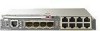
Spare part number g) Brocade 4Gb SAN Switch for HP cClass BladeSystem, 24 ports with Power Pack Software* 411122-001 h) Cisco Catalyst Blade Switch 3020 for 432904-001 HP c-Class BladeSystem* i) HP 1/10Gb Virtual Connect Ethernet Module for c-Class BladeSystem* 399725-001 j) HP 4Gb - HP 3020 | HP BladeSystem c7000 Enclosure Maintenance and Service Guide - Page 25
HP c-Class Blade SUV Cable* 416003-001 No3 Mandatory1 Mandatory1 Mandatory1 Mandatory1 Mandatory1 *Not shown 1Mandatory-Parts for which customer self repair is mandatory. If you request HP to replace these parts, you will be charged for the travel and labor costs of this service. 2Optional-Parts - HP 3020 | HP BladeSystem c7000 Enclosure Maintenance and Service Guide - Page 26
Sie jedoch den Austausch dieser Teile von HP vornehmen lassen möchten, können bei diesem Service je nach den für Ihr Produkt vorgesehenen Obligatorio-componentes para los que la reparación por parte del usuario es obligatoria. Si solicita a HP que realice la sustitución de estos componentes, tendr - HP 3020 | HP BladeSystem c7000 Enclosure Maintenance and Service Guide - Page 27
Illustrated parts catalog 27 - HP 3020 | HP BladeSystem c7000 Enclosure Maintenance and Service Guide - Page 28
10 Torx screwdriver • T-15 Torx screwdriver Safety considerations Before performing service procedures, review parts in their containers until they arrive at static-free workstations. • Place parts instructions. one component is extended at a time. A rack may become unstable if more than one - HP 3020 | HP BladeSystem c7000 Enclosure Maintenance and Service Guide - Page 29
guidelines for manual material handling enclosure on a surface that cannot support up to 217.7 kg (480.0 lb -plug power supplies, server blades, and interconnects are removed cabinet may contain more than one enclosure. Power may be When performing any service other than hot-plug - HP 3020 | HP BladeSystem c7000 Enclosure Maintenance and Service Guide - Page 30
enter enclosures or perform service on system components only as instructed in the user blade and/or the system. Use caution when performing other operations, such as hot-plug installations or troubleshooting one of the following methods to power down the server blades or workstation blades - HP 3020 | HP BladeSystem c7000 Enclosure Maintenance and Service Guide - Page 31
hot-plug device, it is not necessary to power down the storage blades. To power down the storage blades, power down the partner server blades or workstation blades. The storage blades automatically switch to standby mode. The storage blades remain in standby mode as long as power is available to the - HP 3020 | HP BladeSystem c7000 Enclosure Maintenance and Service Guide - Page 32
supply blank To remove the component: CAUTION: This procedure provides instructions for replacement of a failed part only. To change the configuration of components, see the appropriate HP BladeSystem c-Class enclosure setup and installation guide. NOTE: To access all power supply bays, slide the - HP 3020 | HP BladeSystem c7000 Enclosure Maintenance and Service Guide - Page 33
, do not operate the enclosure for extended periods with more than one component or blank removed. When removing an active component, replace it by the vertical support metal work. Within each quadrant, a removable divider supports half-height blades. To install a full-height blade in any quadrant - HP 3020 | HP BladeSystem c7000 Enclosure Maintenance and Service Guide - Page 34
Item 1 2 3 4 Description Blade Zone 1 Blade Zone 2 Blade Zone 3 Blade Zone 4 Storage blades and tape blades can be installed in the same quadrant as both full-height and half-height blades. A bracket ships with each SB40c Storage Blade that allows a half-height blade to be mounted on top of the - HP 3020 | HP BladeSystem c7000 Enclosure Maintenance and Service Guide - Page 35
2. Slide the device bay shelf locking tab to the left to open it. 3. Push the device bay shelf back until it stops, lift the right side slightly to disengage the two tabs from the divider wall, and then rotate the right edge downward (clockwise). Removal and replacement procedures 35 - HP 3020 | HP BladeSystem c7000 Enclosure Maintenance and Service Guide - Page 36
-height blade CAUTION: This procedure provides instructions for replacement of a failed part only. To change the configuration of components, see the appropriate HP BladeSystem c-Class enclosure setup and installation guide. The c7000 enclosure is divided into four quadrants by the vertical support - HP 3020 | HP BladeSystem c7000 Enclosure Maintenance and Service Guide - Page 37
Item 1 2 3 4 Description Blade Zone 1 Blade Zone 2 Blade Zone 3 Blade Zone 4 Storage blades and tape blades can be installed in the same quadrant as both full-height and half-height blades. A bracket ships with each SB40c Storage Blade that allows a half-height blade to be mounted on top of the - HP 3020 | HP BladeSystem c7000 Enclosure Maintenance and Service Guide - Page 38
-height blade o Full-height blade CAUTION: For best cooling practices, do not operate the enclosure for extended periods with more than one component or blank removed. When removing an active component, replace it with a blank. To replace the component, reverse the removal procedure. HP BladeSystem - HP 3020 | HP BladeSystem c7000 Enclosure Maintenance and Service Guide - Page 39
: bays 1-5 ("Half-height or full-height blade" on page 36) o Device bay blanks: bays 9-13 ("Device bay blank" on page 33) o Power supplies or blanks: bays 1-4 ("HP BladeSystem c7000 power supply or power supply blank" on page 32) 3. Remove the three T-15 Torx screws that secure the Insight Display - HP 3020 | HP BladeSystem c7000 Enclosure Maintenance and Service Guide - Page 40
the handle counterclockwise. 2. Remove the blank. CAUTION: For best cooling practices, do not operate the enclosure for extended periods with more than one component or blank removed. When removing an active component, replace it with a blank. To replace the component, reverse the removal procedure - HP 3020 | HP BladeSystem c7000 Enclosure Maintenance and Service Guide - Page 41
Active Cool 200 fan CAUTION: This procedure provides instructions for replacement of a failed part only. To change the configuration of components, see the appropriate HP BladeSystem c-Class enclosure setup and installation guide. To remove the component: 1. Turn the handle counterclockwise. 2. - HP 3020 | HP BladeSystem c7000 Enclosure Maintenance and Service Guide - Page 42
it locks into place. Interconnect switch or Pass-Thru module CAUTION: This procedure provides instructions for replacement of a failed part only. To change the configuration of components, see the appropriate HP BladeSystem c-Class enclosure setup and installation guide. To remove the component - HP 3020 | HP BladeSystem c7000 Enclosure Maintenance and Service Guide - Page 43
more than one component or blank removed. When removing an active component, replace it with a blank. To replace the component, reverse the removal procedure. Interconnect bay dividers To remove the component: 1. Remove the interconnect switches and Pass-Thru modules ("Interconnect switch or Pass - HP 3020 | HP BladeSystem c7000 Enclosure Maintenance and Service Guide - Page 44
blank Remove the component as indicated. CAUTION: For best cooling practices, do not operate the enclosure for extended periods with more than one component or blank removed. When removing an active component, replace it with a blank. To replace the component, reverse the removal procedure. Onboard - HP 3020 | HP BladeSystem c7000 Enclosure Maintenance and Service Guide - Page 45
. 3. Remove the Onboard Administrator module. CAUTION: For best cooling practices, do not operate the enclosure for extended periods with more than one component or blank removed. When removing an active component, replace it with a blank. To replace the component, reverse the removal procedure - HP 3020 | HP BladeSystem c7000 Enclosure Maintenance and Service Guide - Page 46
, do not operate the enclosure for extended periods with more than one component or blank removed. When removing an active component, replace it To remove the component: 1. Power down the server blades ("Power down the server blades or workstation blades" on page 30). 2. Power down the enclosure (on - HP 3020 | HP BladeSystem c7000 Enclosure Maintenance and Service Guide - Page 47
("Half-height or full-height blade" on page 36) o Power supplies ("HP BladeSystem c7000 power supply or power supply blank" on page 32) 5. Remove the fans ("Active Cool 200 fan" on page 41). 6. Remove the interconnect switches and Pass-Thru modules ("Interconnect switch or Pass-Thru module" on - HP 3020 | HP BladeSystem c7000 Enclosure Maintenance and Service Guide - Page 48
b. Use the handles to extend the rear cage until the release levers engage on both sides of the rear cage. c. Grasp the handholds below the release levers. d. Disengage the release levers on both sides of the rear cage. CAUTION: When removing and lifting the rear cage, always grasp the handholds as - HP 3020 | HP BladeSystem c7000 Enclosure Maintenance and Service Guide - Page 49
or full-height blade" on page 36). 5. Remove the device bay blanks ("Device bay blank" on page 33). 6. Remove the power supplies ("HP BladeSystem c7000 power supply or power supply blank" on page 32). 7. Remove the fans ("Active Cool 200 fan" on page 41). 8. Remove the interconnect switches and Pass - HP 3020 | HP BladeSystem c7000 Enclosure Maintenance and Service Guide - Page 50
12. Remove the three T-15 Torx screws that secure the Insight Display cable center cover, and then remove the cover. 13. Disconnect the Insight Display cable. 14. Remove the four T-15 Torx screws that secure the interconnect board cover, and then remove the cover. NOTE: The device bay walls have - HP 3020 | HP BladeSystem c7000 Enclosure Maintenance and Service Guide - Page 51
approximately 8 cm (3 in) before removing or installing the rear cage. To remove the component: 1. Power down the server blades ("Power down the server blades or workstation blades" on page 30). 2. Power down the enclosure (on page 31). 3. Disconnect all cables. Removal and replacement procedures 51 - HP 3020 | HP BladeSystem c7000 Enclosure Maintenance and Service Guide - Page 52
("Half-height or full-height blade" on page 36) o Power supplies ("HP BladeSystem c7000 power supply or power supply blank" on page 32) 5. Remove the fans ("Active Cool 200 fan" on page 41). 6. Remove the interconnect switches and Pass-Thru modules ("Interconnect switch or Pass-Thru module" on - HP 3020 | HP BladeSystem c7000 Enclosure Maintenance and Service Guide - Page 53
serial number and part number using one of the following blade" on page 36) o Power supplies ("HP BladeSystem c7000 power supply or power supply blank" on page 32) 5. Remove the fans ("Active Cool 200 fan" on page 41). 6. Remove the interconnect switches and Pass-Thru modules ("Interconnect switch - HP 3020 | HP BladeSystem c7000 Enclosure Maintenance and Service Guide - Page 54
10-digit enclosure serial number. 3. Enter the SET ENCLOSURE PART_NUMBER X command, where X represents the enclosure part US o 2-Three-phase power, US o 3-Three-phase power, International o 4-DC power Failure to complete this procedure can cause inaccurate or incomplete information to display in HP - HP 3020 | HP BladeSystem c7000 Enclosure Maintenance and Service Guide - Page 55
Cabling Single-phase AC configuration Three-phase AC configuration Cabling 55 - HP 3020 | HP BladeSystem c7000 Enclosure Maintenance and Service Guide - Page 56
HP BladeSystem c7000 Enclosure DC configuration Item 1 2 3 4 5 6 7 8 9 10 Description Chassis grounding lugs DC connectors for power supply bay 1 DC connectors for power supply bay 2 DC connectors for power supply bay 3 DC connectors for - HP 3020 | HP BladeSystem c7000 Enclosure Maintenance and Service Guide - Page 57
Enclosure linkdown port Enclosure linkup port and service port Description Ethernet 1000BaseT RJ45 connector, which provides Ethernet access to the Onboard Administrator and the iLO on each server blades or workstation blades. Also supports interconnect modules with management processors configured - HP 3020 | HP BladeSystem c7000 Enclosure Maintenance and Service Guide - Page 58
Enclosure linkdown port Enclosure linkup port and service port Description Ethernet 1000BaseT RJ45 connector, which provides Ethernet access to the Onboard Administrator and the iLO on each server blades or workstation blades. Also supports interconnect modules with management processors configured - HP 3020 | HP BladeSystem c7000 Enclosure Maintenance and Service Guide - Page 59
offline and online versions, that provides diagnostics and troubleshooting capabilities to assist IT administrators who verify server blades or workstation blades installations, troubleshoot problems, and perform repair validation. HP Insight Diagnostics Offline Edition performs various in-depth - HP 3020 | HP BladeSystem c7000 Enclosure Maintenance and Service Guide - Page 60
spare part numbers for the server blades or workstation blades. To download the latest version, see the HP website (http://www.hp.com/support). the following: • From within HP SIM • From within operating system-specific IML viewers: o For NetWare: IML Viewer o For Windows®: IML Viewer o For Linux: - HP 3020 | HP BladeSystem c7000 Enclosure Maintenance and Service Guide - Page 61
Power supply bay 4 7 Insight Display 8 Power supply bay 5 9 Power supply bay 6 10 Air intake slot (Do not block.) *For more information, see "Device bay numbering (on on the rear of the enclosure. Be sure to review device bay numbering to determine which external network connections on - HP 3020 | HP BladeSystem c7000 Enclosure Maintenance and Service Guide - Page 62
IMPORTANT: When looking at the rear of the enclosure, device bay numbering is reversed. Full-height device bay numbering Half-height device bay numbering Component identification 62 - HP 3020 | HP BladeSystem c7000 Enclosure Maintenance and Service Guide - Page 63
Power supply LEDs Power LED 1 (green) Off On Off Fault LED 2 (amber) Off Off On Condition No AC power to the power supply Normal Power supply failure Power supply bay numbering Component identification 63 - HP 3020 | HP BladeSystem c7000 Enclosure Maintenance and Service Guide - Page 64
the health and operation of the enclosure. See the HP BladeSystem Onboard Administrator User Guide for additional information. The Insight Display background color press OK. For information on driver and firmware updates, see the HP website (http://www.hp.com/go/blades/). Component identification 64 - HP 3020 | HP BladeSystem c7000 Enclosure Maintenance and Service Guide - Page 65
HP BladeSystem Insight Display components Item 1 2 3 4 5 6 Description Insight Display screen Left arrow button Right arrow button OK button Down arrow button Up arrow button Function Displays Main Menu error messages and instructions Moves the menu or navigation bar selection left one position - HP 3020 | HP BladeSystem c7000 Enclosure Maintenance and Service Guide - Page 66
5 Interconnect bay 2 Interconnect bay 4 Interconnect bay 6 Interconnect bay 8 Onboard Administrator bay 2 Power supply exhaust vent (do not block) Fan bay 10 Fan bay 9 Fan bay 8 Fan bay 7 Fan bay 6 AC power connectors Onboard Administrator bay 1 Interconnect bay 7 Interconnect bay 5 Interconnect bay - HP 3020 | HP BladeSystem c7000 Enclosure Maintenance and Service Guide - Page 67
Server blade signal NICs 1, 2, 3, and 4 (embedded) Mezzanine 1 Mezzanine 2 Mezzanine 3 Interconnect bay number 1, 2 3, 4 port option card is installed in mezzanine slot 3 in a full-height server blades or workstation blades, then ports 1 and 2 are connected to interconnect bays 7 and 8, respectively - HP 3020 | HP BladeSystem c7000 Enclosure Maintenance and Service Guide - Page 68
Onboard Administrator LEDs and buttons Item 1 2 3 4 5 Description Onboard Administrator UID LED Enclosure UID LED and UID button Onboard Administrator active LED Onboard Administrator health LED Onboard Administrator reset button Onboard Administrator with KVM LEDs and buttons Item Description - HP 3020 | HP BladeSystem c7000 Enclosure Maintenance and Service Guide - Page 69
Item 2 3 4 5 Description Enclosure UID LED and UID button Onboard Administrator health LED Onboard Administrator active LED Onboard Administrator reset button Fan bay numbering Fan LED LED color Solid green Solid amber Fan status The fan is working. The fan has failed. Component identification - HP 3020 | HP BladeSystem c7000 Enclosure Maintenance and Service Guide - Page 70
LED color Flashing amber Fan status See the Insight Display screen. Component identification 70 - HP 3020 | HP BladeSystem c7000 Enclosure Maintenance and Service Guide - Page 71
Specifications Environmental specifications Specification Value Temperature range* Operating Non-operating Wet bulb temperature Operating Non-operating 10°C to 35°C (50°F to 95°F) -30°C to 60°C (-22°F to 140°F) 28ºC (82.4ºF) 38.7ºC (101.7ºF) Relative humidity (noncondensing)** Operating 20% - HP 3020 | HP BladeSystem c7000 Enclosure Maintenance and Service Guide - Page 72
.0 kg (450.0 lb) 223.6 kg (493.0 lb) Power specifications DC power Specification Output Input requirements Rated input voltage Rated input current per power supply VAC 200 VAC to 240 VAC 50 Hz to 60 Hz 11.7 A at 100 VAC 10.6 A at 110 VAC 10.1 A at 115 VAC 9.7 A at 120 VAC 13.1 A at 200 VAC 12.6 - HP 3020 | HP BladeSystem c7000 Enclosure Maintenance and Service Guide - Page 73
21.8 A at 208 VAC 20.6 A at 220 VAC 7836 VA Three-phase power (International) Specification Power cords (2) Output Input requirements Rated input voltage Rated input frequency Value IEC-309 200/346-V to 240/415-V, 5pin, 16-A 2.44 m (10 ft) 2250 W 346 VAC to 415 VAC line-to-line* 200 VAC to 240 - HP 3020 | HP BladeSystem c7000 Enclosure Maintenance and Service Guide - Page 74
Interface CSR Customer Self Repair ESD electrostatic discharge I/O input/output iLO Integrated Lights-Out IML Integrated Management Log ISEE Instant Support Enterprise Edition LCD liquid crystal display OA Onboard Administrator SAN storage area network SFP small form-factor pluggable Acronyms and - HP 3020 | HP BladeSystem c7000 Enclosure Maintenance and Service Guide - Page 75
SIM Systems Insight Manager SNMP Simple Network Management Protocol Acronyms and abbreviations 75 - HP 3020 | HP BladeSystem c7000 Enclosure Maintenance and Service Guide - Page 76
specifications blade shelf 33 HP BladeSystem Insight Display 38, 64 HP BladeSystem Insight Display components 65 HP BladeSystem Insight Display screen 61, 64, 65 HP BladeSystem Insight Display, navigating 65 HP BladeSystem Insight Display, overview of 64 HP Insight Diagnostics 59 I illustrated parts - HP 3020 | HP BladeSystem c7000 Enclosure Maintenance and Service Guide - Page 77
, HP BladeSystem Insight Display 64 P part numbers blade bay numbering 61 server blade enclosure bay numbering 61 single-phase AC configuration 55 spare part numbers 16 specifications 71, 73 static electricity 28 system components 20, 23, 61 T three-phase AC configuration 55 tools 59 troubleshooting
-
 1
1 -
 2
2 -
 3
3 -
 4
4 -
 5
5 -
 6
6 -
 7
7 -
8
-
9
-
10
-
11
-
12
-
13
-
14
-
15
-
16
-
17
-
18
-
19
-
20
-
21
-
22
-
23
-
24
-
25
-
26
-
27
-
28
-
29
-
30
-
31
-
32
-
33
-
34
-
35
-
36
-
37
-
38
-
39
-
40
-
41
-
42
-
43
-
44
-
45
-
46
-
47
-
48
-
49
-
50
-
51
-
52
-
53
-
54
-
55
-
56
-
57
-
58
-
59
-
60
-
61
-
62
-
63
-
64
-
65
-
66
-
67
-
68
-
69
-
70
-
71
-
72
-
73
-
74
-
75
-
76
-
77
 |
 |

HP BladeSystem c7000 Enclosure
Maintenance and Service Guide
Part Number 413336-007
October 2009 (Seventh Edition)