HP 3500 Service Manual
HP 3500 - Color LaserJet Laser Printer Manual
 |
View all HP 3500 manuals
Add to My Manuals
Save this manual to your list of manuals |
HP 3500 manual content summary:
- HP 3500 | Service Manual - Page 1
hp color LaserJet 3500/3550 and 3700 series printer service - HP 3500 | Service Manual - Page 2
- HP 3500 | Service Manual - Page 3
HP Color LaserJet 3500/3550 and 3700 series printers Service Manual - HP 3500 | Service Manual - Page 4
Hewlett-Packard Development Company, L.P. Reproduction, adaptation or translation without prior written permission is prohibited, except as allowed under the copyright laws. The information contained herein is subject to change without notice. The only warranties for HP products and services - HP 3500 | Service Manual - Page 5
Conventions NOTE CAUTION WARNING! This manual uses the following conventions: Color is used to emphasize items that . DISPLAY type indicates text as seen on the printer control panel display. Commands you use on a computer keyboard or on the printer control panel are shown in Keycap. Two examples - HP 3500 | Service Manual - Page 6
iv ENWW - HP 3500 | Service Manual - Page 7
media specifications ...16 Supported media weights and sizes 16 Hewlett-Packard warranty statement 19 HP's Premium Protection Print Cartridge Warranty Limited Warranty Statement 20 Premium Protection Warranty Color LaserJet Image Fuser Kit and Image Transfer Kit Limited Warranty Statement 21 - HP 3500 | Service Manual - Page 8
) configuration (HP color LaserJet 3700 series printer only 69 HP Jetdirect print servers 69 Available enhanced I/O interfaces 69 NetWare networks ...70 Windows and Windows NT networks 70 AppleTalk networks ...70 UNIX/Linux networks ...70 Printer software ...71 Printer drivers ...71 Software for - HP 3500 | Service Manual - Page 9
for supplies for the HP Color LaserJet 3500 series printer ...94 Approximate replacement intervals for supplies for the HP Color LaserJet 3550/3700 series printer 94 Locating supplies and parts ...96 Replacing supply items ...97 Replacing the transfer unit 99 Replacing the fuser and pickup roller - HP 3500 | Service Manual - Page 10
output bin) removal 215 Tray 1 (multipurpose) removal 216 Main Assemblies ...217 Transfer unit removal ...218 Print cartridge removal 219 Fuser removal ...220 Face-down delivery assembly removal 221 Laser/scanner assembly removal 222 Image drive assembly removal 223 Developing engaging drive - HP 3500 | Service Manual - Page 11
(PS10) removal (HP 3700 only 258 Rear output bin paper sensor (PS11) removal 259 Color misregistration sensor (PS12) removal 260 Waste toner level sensor (PS13) removal 260 Developing engaging sensor (PS14) removal 261 Environment sensor (PS15) removal 261 Secondary transfer roller engaging - HP 3500 | Service Manual - Page 12
jams 382 Print quality problems associated with toner buildup 382 Print quality troubleshooting pages 383 Calibrating the printer ...383 Using Color ...384 HP ImageREt 2400 ...384 Paper selection ...384 Color options (available for the HP Color LaserJet 3700 series printer 384 Standard red-green - HP 3500 | Service Manual - Page 13
411 System setup menu ...414 I/O menu ...418 Resets menu ...419 Diagnostics menu ...419 Service menu ...420 Tools for troubleshooting ...422 Embedded Web server (HP Color LaserJet 3700 series printer only 422 HP Toolbox ...424 Printer configuration page 428 Supplies status page ...429 Usage page - HP 3500 | Service Manual - Page 14
...433 Engine diagnostics ...434 Diagnostics from the Control Panel 436 Printer display menu ...436 Diagnostics test menu ...436 Paper Path Test 447 Calibrate Now ...447 Service menu ...448 Accessing the Service menu 448 Diagrams ...450 Main parts ...451 Switches ...452 Sensors ...453 Solenoids - HP 3500 | Service Manual - Page 15
models of the HP Color LaserJet 3700 series printer)1 17 Model names and numbers 22 Weight equivalence table 29 Related documentation and software 45 Printer drivers for the HP Color LaserJet 3500/3550 series printer 71 Printer drivers for the HP Color LaserJet 3700 series printer 72 Other - HP 3500 | Service Manual - Page 16
for reversed color 400 Repetitive defect cause 401 Communications check 403 Information menu 408 Paper handling menu 408 Printing menu 409 Print quality menu 412 System setup submenu 415 I/O submenu 418 Resets submenu 419 Diagnostics menu 419 Service menu 420 Paper path and manual sensor - HP 3500 | Service Manual - Page 17
Table 8-26. Table 8-27. Table 8-28. Left swing frame assembly 529 Fuser assembly 531 500-Sheet paper feeder main body 533 500-Sheet paper feeder paper pick-up drive assembly 535 500-Sheet paper feeder tray (Tray 3 537 Alphabetical parts list 538 Numerical parts list 551 ENWW Conventions xv - HP 3500 | Service Manual - Page 18
xvi ENWW - HP 3500 | Service Manual - Page 19
5-19. HP Color LaserJet 3500/3550 printer 3 HP Color LaserJet 3500n/3550n printer 3 HP Color LaserJet 3700 printer 4 HP Color LaserJet 3700n printer 4 HP Color LaserJet 3700dn printer 5 HP Color LaserJet 3700dtn printer 5 Front view, HP Color LaserJet 3500/3550 and 3700 series printers (shown - HP 3500 | Service Manual - Page 20
/disengaging unit 159 Memory tag control 160 Cartridge presence detection 161 Toner level detection 162 Transfer section diagram 164 Transfer section 166 ITB cleaning control 167 Waste toner full detection 168 Transfer unit detection 169 Transfer unit life detection control 169 ITB self - HP 3500 | Service Manual - Page 21
removal 215 Tray 1 removal 216 Main internal assemblies 217 Transfer unit removal 219 Transfer unit installation 219 Print cartridge removal 220 Fuser removal 221 Face-down delivery assembly removal 222 Laser/scanner assembly removal 223 Image drive assembly removal 224 Developing engaging - HP 3500 | Service Manual - Page 22
Figure 6-113. Transfer roller engaging motor (4 of 4 277 Figure 6-114. Fan removal 277 Figure 6-115. Circuit board locations 278 Figure 6-116. DC controller PCB removal 279 Figure 6-117. Formatter PCB (HP 3500/3550) removal (1 of 2 280 Figure 6-118. Formatter PCB (HP 3500/3500) removal (2 of - HP 3500 | Service Manual - Page 23
guide removal (1 of 6 291 Figure 6-137. Right Tray 2 guide removal (2 of 6 292 Figure 6-138. Right Tray 2 guide removal (3 of 6 292 Figure 6-139. Right Tray 2 guide removal (4 of 6 293 Figure 6-140. Right Tray 2 guide 7-6. Printer menu map (HP 3700 shown 407 Figure 7-7. Printer configuration - HP 3500 | Service Manual - Page 24
the HP Color LaserJet 3500/3550 printer (1 of 2) . .460 Connector locations for the HP Color LaserJet 3500/3550 printer (2 of 2) . .461 Connector locations for the 500-sheet paper feeder 462 General circuit diagram (1 of 2 463 General circuit diagram (2 of 2 464 Main parts (1 of 3 478 Main parts - HP 3500 | Service Manual - Page 25
media specifications ...16 Supported media weights and sizes 16 Hewlett-Packard warranty statement 19 HP's Premium Protection Print Cartridge Warranty Limited Warranty Statement 20 Premium Protection Warranty Color LaserJet Image Fuser Kit and Image Transfer Kit Limited Warranty Statement 21 - HP 3500 | Service Manual - Page 26
Laser safety statement ...37 Canadian DOC regulations 37 EMI statement (Korea) ...37 VCCI statement (Japan 37 Laser statement for Finland 38 FCC Regulations ...39 2 Chapter 1 Printer description ENWW - HP 3500 | Service Manual - Page 27
dynamic random access memory (SDRAM). HP Color LaserJet 3500n/3550n printer Figure 1-2. HP Color LaserJet 3500n/3550n printer The HP Color LaserJet 3500n/3550n printer includes the features of the HP Color LaserJet 3500/3550 printer, plus an HP Jetdirect en3700 external print server for - HP 3500 | Service Manual - Page 28
64, 128, or 256 MB RAM each. This printer can support up to 448 MB of memory. HP Color LaserJet 3700n printer Figure 1-4. HP Color LaserJet 3700n printer The HP Color LaserJet 3700n printer includes the features of the HP Color LaserJet 3700 printer, plus an HPJetdirect 615n print server for easy - HP 3500 | Service Manual - Page 29
HP Color LaserJet 3700dn printer The HP Color LaserJet 3700dn printer includes the features of the HP Color LaserJet 3700n printer, automatic two-sided (duplex) printing, and a total of 128 MB of SDRAM. HP Color LaserJet 3700dtn printer Figure 1-6. HP Color LaserJet 3700dtn printer The HP Color - HP 3500 | Service Manual - Page 30
status and troubleshooting information). ● Windows PC and Apple Macintosh print drivers. ● Embedded Web server to access support and order supplies (administrator tool for network-connected printers). ● HP JetReady 4.1 for the HP Color LaserJet 3500/3550 series printer. ● HP PCL 6. ● PostScript - HP 3500 | Service Manual - Page 31
(continued) Feature HP Color LaserJet 3500/3550 series printer HP Color LaserJet 3700 series printer Fonts ● Not applicable. ● 80 internal fonts available for both PCL and PostScript emulation. ● 80 printer-matching screen fonts in TrueTypeTM format available with the software solution. Paper - HP 3500 | Service Manual - Page 32
3500n/3550n printer. ● Optional enhanced input/ output (EIO) network card; ● HP Web Jetadmin software. standard on HP Color LaserJet 3700n, 3700dn, and 3700dtn printers. ● eP Embedded Web server. ● HP Web Jetadmin software. Supplies ● Supplies status page contains information on toner - HP 3500 | Service Manual - Page 33
of each major assembly in the printer. These assemblies are described in the Installation and configuration chapter. Figure 1-7. Front view, HP Color LaserJet 3500/3550 and 3700 series printers (shown with additional 500-sheet paper feeder) 1 On/off switch 2 Tray 3 (optional; 500 sheets of - HP 3500 | Service Manual - Page 34
sheets of standard paper) 4 USB connection 5 Power connection 6 Tray 3 (optional) 7 On/off switch 8 EIO connection (available on the HP Color LaserJet 3700 series printer) 9 DIMM access door (available on the HP Color LaserJet 3700 series printer) 10 Chapter 1 Printer description ENWW - HP 3500 | Service Manual - Page 35
the figures Figure 1-9. Space requirements for the HP Color LaserJet 3500/3550 series printer and Figure 1-10. Space requirements for the HP Color LaserJet 3700 series printer with optional Tray 3, on the following pages.) Space requirements The printer must have the following amounts of space above - HP 3500 | Service Manual - Page 36
Table 1-3. Power consumption for 110 and 220-volt (average in watts)1 Product Printing2 Ready3 Power Save4 Off HP Color 400 25 25 0.25 LaserJet 3500/3550 HP Color 400 26 26 0.25 LaserJet 3500n/3550n Heat outputReady (BTU/ hour) 85 89 12 Chapter 1 Printer description ENWW - HP 3500 | Service Manual - Page 37
information, see http://www.hp.com/support/ clj3500 for the HP Color LaserJet 3500 series printer, http://www.hp.com/support/clj3550 for the HP Color LaserJet 3550 series printer, or http://www.hp.com/support/clj3700 for the HP Color LaserJet 3700 series printer. Environmental specifications Keep - HP 3500 | Service Manual - Page 38
35% RH Atmospheric pressure 460 to 760 mm Hg (18.1 to 29.9 in Hg) Storage time1 2.5 years 1The average storage time includes use time. Use cartridges within 2.5 years of the date code on the cartridge. 14 Chapter 1 Printer description ENWW - HP 3500 | Service Manual - Page 39
.hp.com/support/ clj3500 for the HP Color LaserJet 3500 series printer, http://www.hp.com/support/clj3550 for the HP Color LaserJet 3550 series printer, or http://www.hp.com/support/clj3700 for the HP Color LaserJet 3700 series printer. Duty cycle The HP Color LaserJet 3500 series printer maximum - HP 3500 | Service Manual - Page 40
250 (Sheffield). 2Use only transparencies designed for use with HP Color LaserJet printers. This printer can detect transparencies that were not designed for use with HP Color LaserJet printers. The following table lists the standard sizes of paper that the printer supports in Tray 2. 16 Chapter - HP 3500 | Service Manual - Page 41
. The following table lists the standard sizes of paper that the printer supports in Tray 3. Table 1-10. Tray 3 paper sizes1 Media Dimensions Table 1-11. Automatic two-sided printer (available on some models of the HP Color LaserJet 3700 series printer)1 Media Dimensions Weight or thickness - HP 3500 | Service Manual - Page 42
Manual two-sided printing. Any of the supported paper sizes and types listed for printing from Tray 1 can be manually duplexed. See the two-sided (duplex) printing section in the HP Color LaserJet 3550 and 3700 series printer User Guide for more information. 18 Chapter 1 Printer description ENWW - HP 3500 | Service Manual - Page 43
Hewlett-Packard warranty statement HP PRODUCT HP Color LaserJet 3500, 3500n, 3550, 3550n, 3700, 3700n, 3700dn, and 3700dtn printers DURATION OF LIMITED WARRANTY One-year limited warranty HP warrants to you, the end-user customer, that HP hardware and accessories will be free from defects in - HP 3500 | Service Manual - Page 44
environmental specifications for the printer product or (c) exhibit wear from ordinary use. To obtain warranty service, please return the product to place of purchase (with a written description of the problem and print samples) or contact HP customer support. At HP's option, HP will either replace - HP 3500 | Service Manual - Page 45
Premium Protection Warranty Color LaserJet Image Fuser Kit and Image Transfer Kit Limited Warranty Statement This HP product is warranted to be free from defects in materials and workmanship until the printer provides a low-life indicator on the control panel. This warranty does not apply to - HP 3500 | Service Manual - Page 46
12. Model names and numbers Model name HP Color LaserJet 3500 HP Color LaserJet 3500n HP Color LaserJet 3550 HP Color LaserJet 3550n HP Color LaserJet 3700 HP Color LaserJet 3700n HP Color LaserJet 3700dn HP Color LaserJet 3700dtn Model number Q1319A Q1320A Q5990A Q5991A Q1321A Q1322A Q1323A Q1324A - HP 3500 | Service Manual - Page 47
Converting the voltage on the printer can damage the printer. Do not use any voltage other than the operating voltage. Any attempt to convert operating voltages will void the product warranty (for example, attempting to change a 110V printer to a 220V printer). Figure 1-12. Sample label ENWW - HP 3500 | Service Manual - Page 48
. To download a copy of the HP LaserJet Printer Family Print Media Specification Guide go to http://www.hp.com/support/ clj3500 for the HP Color LaserJet 3500 series, to http://www.hp.com/support/clj3500 for the HP Color LaserJet 3550 series and to http://www.hp.com/support/clj3700 for the HP Color - HP 3500 | Service Manual - Page 49
for the temperatures of the HP Color LaserJet 3500/3550 and 3700 series printer image fusers. Select paper that can tolerate temperatures of 190°C (374°F) for 0.1 second. HP produces a selection of paper that is designed for the HP Color LaserJet 3500/3550 and 3700 series printer. ● Do not use - HP 3500 | Service Manual - Page 50
problems. ● Use only overhead transparencies recommended for use in this printer. Hewlett-Packard recommends using HP Color LaserJet Transparencies with this printer. HP products are designed to work together for optimum printing results. ● In either the software application or the printer driver - HP 3500 | Service Manual - Page 51
bond). ● Envelopes should be flat. ● Do not use envelopes with windows or clasps. ● Envelopes must not be wrinkled, nicked, or otherwise HP Color LaserJet 3550 and 3700 series printer User Guide to change the printer driver envelope orientation. Labels In either the application or the printer driver - HP 3500 | Service Manual - Page 52
loading preprinted paper such as forms and letterhead, verify that the ink on the paper is dry. During the fusing process, wet ink can come off preprinted paper. ● When duplex printing on the HP Color LaserJet 3700 series printer, load preprinted forms and letterhead into Tray 2 and Tray 3 first - HP 3500 | Service Manual - Page 53
NOTE ENWW Recycled paper This printer supports the use of recycled paper. Recycled paper must meet the same specifications as standard paper. See the HP LaserJet Printer Family Print Media Specification Guide. Hewlett-Packard recommends that recycled paper contain no more than five percent ground - HP 3500 | Service Manual - Page 54
# 98# 120# 146# 72# 183# 100# 123# 150# 150# 154# 155# 162# 166# 244 g/m2 250 g/m2 253 g/m2 264 g/m2 271 g/m2 30 Chapter 1 Printer description ENWW - HP 3500 | Service Manual - Page 55
is described in this section. Protecting the environment Hewlett-Packard Company is committed to providing quality products in an on natural resources. The HP Color LaserJet 3550, 3550n, 3700, and 3700n printers support the manual duplex feature. Plastics Plastic parts over 25 grams are marked - HP 3500 | Service Manual - Page 56
return and recycling free of charge in 86% of the world market where HP LaserJet supplies are sold. Postage-paid and pre-addressed labels are included within the instruction guide in most HP LaserJet print cartridge boxes. Labels and bulk boxes are also available through the Website: http://www - HP 3500 | Service Manual - Page 57
a three-year period from date of the HP product purchase. The customer must purchase the HP SupportPack within 90 days of the HP product purchase. For more information, contact the HP Customer Care Service and HP Customer Support group. See Hewlett-Packard warranty statement. For more information On - HP 3500 | Service Manual - Page 58
to ISO/IEC Guide 22 and EN 45014 Manufacturer's Name: Manufacturer's Address: Hewlett-Packard Company 11311 Chinden Boulevard Boise, Idaho 83714-1021, USA declares, that the product Product Name: Regulatory Model Number:3) Product Options: HP Color LaserJet 3500 HP Color LaserJet 3550 BOISB - HP 3500 | Service Manual - Page 59
CFR, Part 15 Class HP Color LaserJet 3700 series) or the product numbers (Q1321A, Q1322A, Q1323A, Q1324A). Boise, Idaho 83713, USA 1 August 2004 For Regulatory Topics Only: Australia Contact: Product Regulations Manager, Hewlett-Packard Hewlett-Packard Sales and Service Office or Hewlett-Packard - HP 3500 | Service Manual - Page 60
Laser/LED) GB 4943: 1995 EMC : EN 55022: 1998 Class B1) FCC Title 47 CFR, Part 15 Class B ICES-003 Issue 4: 2004 EN 55024: 1998 +A1 2001 + A2: 2003 EN Topics Only: European Contact Your Local Hewlett-Packard Sales and Service Office or Hewlett-Packard Gmbh, Department HQ-TRE / Standards - HP 3500 | Service Manual - Page 61
emitted inside the printer is completely confined within protective housings and external covers, the laser beam cannot escape during any phase of normal user operation. Using controls, making adjustments, or performing procedures other than those specified in this service manual may result in - HP 3500 | Service Manual - Page 62
ättas för osynlig laserstr?lning, som överskrider gränsen för laserklass 1. HUOLTO HP Color LaserJet 3500, 3500n, 3550, 3550n, 3700, 3700n, 3700dn, 3700dtn -kirjoittimen sisällä ei ole säteilyominaisuuksista: Aallonpituus 775-795 nm Teho 5 m W Luokan 3B laser. 38 Chapter 1 Printer description ENWW - HP 3500 | Service Manual - Page 63
to Part 15 of the FCC rules. These limits are designed to provide reasonable protection against harmful interference in a residential installation. This equipment generates, uses, and can radiate radio frequency energy. If this equipment is not installed and used in accordance with the instructions - HP 3500 | Service Manual - Page 64
40 Chapter 1 Printer description ENWW - HP 3500 | Service Manual - Page 65
...44 World Wide Web ...44 HP service parts information CD-ROM 44 HP support assistant CD-ROM 44 Customer care reseller sales and service support center 44 Ordering related documentation and software 45 HP maintenance agreements 46 On-site service agreements 46 ENWW Chapter contents 41 - HP 3500 | Service Manual - Page 66
or in the printer engine. 3. Troubleshoot the problem. Once a faulty part is located, the printer can usually be repaired at the assembly level by replacing field-replaceable units (FRUs). Some mechanical assemblies might need to be repaired at the subassembly level. Hewlett-Packard does not support - HP 3500 | Service Manual - Page 67
designed for this printer. Accessories can be ordered from an authorized service or support provider. See Ordering related documentation and software later in this chapter and Ordering parts in chapter 8 for additional ordering information. By phone: Hewlett-Packard Customer Support-Americas (HPCS - HP 3500 | Service Manual - Page 68
from Hewlett-Packard Customer Support-Americas (HPCS-A) or HewlettPackard Customer Support-Europe (HPCS-E). Supplies Paper and print cartridges can be ordered directly from Hewlett-Packard. See chapter 8 for ordering information. World Wide Web Printer drivers, updated HP printer software, and - HP 3500 | Service Manual - Page 69
) ● Hewlett-Packard Customer Support-Europe (HPCS-E) (49) (70) 311 4225 (3) Table 2-1. Related documentation and software Description HP LaserJet Family Print Media Guide Part Number 5851-1468 HP Color LaserJet 3500 Series Getting Started Guide HP Color LaserJet 3550 Series Getting Started Guide - HP 3500 | Service Manual - Page 70
of maintenance agreements that meet a wide range of support needs. Maintenance agreements are not part of the standard warranty. Support services may vary by area. Check with your local HP dealer to determine the services available to you. On-site service agreements To provide you with the level of - HP 3500 | Service Manual - Page 71
...70 Printer software ...71 Printer drivers ...71 Software for networks ...72 Utilities ...73 Setting security on the printer 76 Locking the control panel 76 Using an ASCII PJL escape sequence to set security 77 Printer memory for the HP Color LaserJet 3700 series printer 78 Installing memory - HP 3500 | Service Manual - Page 72
3500/3550 printer package contents 1 HP Color LaserJet 3500/3550 2 USB cable 3 Power cable 4 Four print cartridges 5 CD-ROM (the CD-ROM contains the user guide) 6 Control panel overlay 7 Getting started guide Figure 3-2. Additional contents shipped with the HP Color LaserJet 3500n - HP 3500 | Service Manual - Page 73
-sheet paper feeder tray) 3 Power cable 4 Four print cartridges 5 CD-ROM (the CD-ROM contains the user guide) 6 Control panel overlay 7 Getting started guide Parallel and USB cables are not included with HP Color LaserJet 3700 series printers. Use an IEEE 1284-compliant, parallel cable or - HP 3500 | Service Manual - Page 74
printer at a later date. The printer weighs approximately 33.5 kg (73.3 lbs). HP recommends having two or more people lift or move the printer percent relative humidity. NOTE If the printer has an optional 500-sheet paper feeder, it is packaged on top of the printer. Lift the 500-sheet paper feeder - HP 3500 | Service Manual - Page 75
move the printer. Do not lift the printer by the Tray 2 handle. NOTE 3. If you are using an optional 500-sheet paper feeder, lift the printer using the handles and align the pegs on Tray 3. Lower the printer onto the tray. Only one Tray 3 (500-sheet input tray) can be installed. ENWW Unpacking - HP 3500 | Service Manual - Page 76
4. Remove all external orange tape, orange protectors, and other packaging material. 5. Open Tray 2 and Tray 3 (if necessary), and remove the orange shipping lock inside each tray. 52 Chapter 3 Installation and configuration ENWW - HP 3500 | Service Manual - Page 77
handle, and pull down the front door. When you open the front door, you will hear components clicking. CAUTION Do not place anything on the transfer unit. Do not touch the top of the transfer unit or the contacts on the left side of the transfer unit. ENWW Unpacking the printer 53 - HP 3500 | Service Manual - Page 78
9. Remove the orange tape and orange shipping locks on the rear, left, and right sides of the transfer unit. Remove any remaining tape from the printer. 54 Chapter 3 Installation and configuration ENWW - HP 3500 | Service Manual - Page 79
Installing the print cartridge 1. Remove a new print cartridge from the bag. 2. Grasp both sides of the print cartridge and distribute the toner by gently rocking the cartridge from side to side. NOTE 3. Remove and discard the orange shipping tape and the shipping locks from the new print - HP 3500 | Service Manual - Page 80
4. Locate the color slot for the print cartridge. 5. Align the print cartridge with the tracks inside the printer and, using the handle, insert the cartridge. Repeat this procedure for the remaining three cartridges. 6. Firmly close the front door. 56 Chapter 3 Installation and configuration ENWW - HP 3500 | Service Manual - Page 81
3 (optional) 1. Pull the tray out of the printer. 2. Adjust the length guides. ● Letter-size paper: Raise the blue rear stop. ● A4-size paper: Lower the blue rear stop. 3. Adjust the width guides. ● Letter-size paper: Press the center of the side width guides outward as far as possible. ● A4-size - HP 3500 | Service Manual - Page 82
stack of paper is flat in the tray at all four corners, and keep it below the height tabs. 6. Slide the tray back into the printer. 58 Chapter 3 Installation and configuration ENWW - HP 3500 | Service Manual - Page 83
Loading paper into Tray 2 1. Pull Tray 2 out of the printer. 2. Move the side width guides until the blue arrows on the width guides point to the size of paper you are loading. 3. On the back of the tray, press the blue ridges and slide the length guides until the arrow symbol points to the paper - HP 3500 | Service Manual - Page 84
place. Make sure that the stack of paper is flat and that the paper is below the height tabs. 6. Slide the tray back into the printer. Raise the output bin extension. 60 Chapter 3 Installation and configuration ENWW - HP 3500 | Service Manual - Page 85
media, such as envelopes, use Tray 1. 2. Slide out the tray extender and, if necessary, open the additional tray extender. 3. Slide the width guides slightly wider than the print media. Remove any unused print media, and close the tray when finished printing. ? ENWW Loading paper into Tray - HP 3500 | Service Manual - Page 86
power NOTE 1. Connect the AC power cord to the printer and to a power outlet. Do not connect the printer to the computer or to the network at this time. 2. Turn the printer on. After a minimum of two minutes, the green ready light turns on. 62 Chapter 3 Installation and configuration ENWW - HP 3500 | Service Manual - Page 87
Installing a new control panel overlay (optional) Overlays are available for several languages and come shipped with the printer. If you are setting up a printer for a language other than English, complete the following procedure. 1. Select the language from the sheet of adhesive control panel - HP 3500 | Service Manual - Page 88
MENUS. 2. Press to highlight Information. 3. Press to select Information. 4. Press to highlight PRINT DEMO. 5. Press to select PRINT CONFIGURATION. After printing the demo page, the printer control panel displays the Ready message. 64 Chapter 3 Installation and configuration ENWW - HP 3500 | Service Manual - Page 89
, or to 1 HOUR, 1.5 HOURS, 2 HOURS, or 4 HOURS. The default setting is 30 MINUTES. The printer display appears dimmed when the printer is in PowerSave mode. PowerSave mode does not affect printer warm-up time, unless the printer is in PowerSave mode for more than eight hours. To set PowerSave Time - HP 3500 | Service Manual - Page 90
All printer models support USB connections. The USB port is on the back of the printer. Connecting the USB cable Plug the USB cable into the printer. Plug the other end of the USB cable into the computer. Figure 3-5. USB connection 1 USB port 2 USB connector 66 Chapter 3 Installation and - HP 3500 | Service Manual - Page 91
see Printer software, later in this chapter. Factory settings support automatic switching between the parallel port and one or more network connections on the printer. If the parallel cable is plugged in, the USB port is disabled. ENWW Parallel configuration (HP Color LaserJet 3700 series printer - HP 3500 | Service Manual - Page 92
HP Color LaserJet 3700 series printer when an EIO device is installed. You might need to configure certain network parameters on the printer. You can configure these parameters from the printer control panel, the embedded Web server, or for most networks, from the HP Web Jetadmin software or the HP - HP 3500 | Service Manual - Page 93
) ● Internet printing For a summary of available network software solutions, see the HP Jetdirect Print Server Administrator's Guide, or visit HP Customer Care online at http://www.hp.com/support/ net_printing. ENWW Enhanced I/O (EIO) configuration (HP color LaserJet 3700 series printer only) 69 - HP 3500 | Service Manual - Page 94
mode. The HP Jetdirect print server supports Novell Directory Services (NDS), as well as bindery modes. For more information, see the HP Jetdirect Print Server Administrator's Guide. For Windows 98, Me, NT 4.0, 2000, and XP systems, use the printer installation utility for printer setup on a NetWare - HP 3500 | Service Manual - Page 95
printer drivers, updated HP printer software, and product support information for the HP Color LaserJet 3500 series printer, go to http://www.hp.com/support/clj3500. For the HP Color LaserJet 3550 series printer, go to http://www.hp.com/support/clj3550. For the HP Color LaserJet 3700 series printer - HP 3500 | Service Manual - Page 96
. 3For Windows XP (64 bit), download the PCL 6 driver from http://www.hp.com/go/ clj3700_software. If your system did not automatically check the Internet for the latest drivers during software installation, download them for the HP Color LaserJet 3500 series printer from http://www.hp.com/go - HP 3500 | Service Manual - Page 97
installation utility for HP-UX and Solaris networks. It is available for download from HP Customer Care Online at http://www.hp.com/support/net_printing. Linux For information about Linux support, go to http://www.hp.com/go/linux. Utilities The HP Color LaserJet 3500/3550 series printer and the HP - HP 3500 | Service Manual - Page 98
computer or when it is connected to a network. You must have performed a complete software installation to use the HP Toolbox. Embedded Web server (available for the HP Color LaserJet 3700 series printer) This printer is equipped with an embedded Web server that allows access to information about - HP 3500 | Service Manual - Page 99
. Table 3-3. Other software applications Windows Macintosh OS ● Software installer- ● PostScript Printer automates the printing Description files (PPDs)- system installation for use with the Apple ● Online Web registration PostScript drivers that come with the Mac OS ● HP toolbox-a Web - HP 3500 | Service Manual - Page 100
Denied MENUS LOCKED You can use HP Web Jetadmin software, the HP LaserJet Utility for Macintosh, or an ASCII escape sequence to perform this procedure. For instructions on locking the printer control panel using either the HP Web Jetadmin software or the HP LaserJet Utility for Macintosh, see the - HP 3500 | Service Manual - Page 101
MS-DOS® or Windows ASCII editor to create the commands. The commands must also be sent to the printer by using a DOS COPY command or an ASCII file download utility. The PJL Technical Reference Manual is located on CD-ROM, part number 5961-0976. Order a copy of this manual from the HP website at http - HP 3500 | Service Manual - Page 102
memory for the HP Color LaserJet 3700 series printer NOTE NOTE NOTE The printer has three DIMM slots. The bottom slot is for the firmware DIMM. For maximum flexibility in DIMM support, the formatter is designed with three 168-pin DIMM slots and a fourth 100-pin DIMM slot. Use these DIMM slots - HP 3500 | Service Manual - Page 103
memory and font DIMMs NOTE You can install more memory for the printer, and you can also install a font DIMM to allow the printer to print characters for languages such as Chinese or the Cyrillic alphabet. Static electricity can damage DIMMs. When handling DIMMs, either wear an antistatic - HP 3500 | Service Manual - Page 104
by gently prying it with a flat-bladed screwdriver. Remove the door by pulling the door toward the back of the printer. 4. Loosen the screws that hold the formatter door to the printer and remove the formatter door. 5. Remove the DIMM from the antistatic package. Locate the alignment notches on the - HP 3500 | Service Manual - Page 105
with the bars in the slot. If the DIMM still does not go in, make sure you are using the correct type of DIMM. ENWW Installing memory and font DIMMs 81 - HP 3500 | Service Manual - Page 106
at the bottom of the slot, and turn the screws to secure the formatter door to the printer. 9. Replace the DIMM access door by inserting the tabs on the door into the slots on the printer. Swing the door shut. 10. Reconnect the power cable and the USB/parallel cable. 82 Chapter - HP 3500 | Service Manual - Page 107
, go to Enabling memory. If you installed a language font DIMM, go to Enabling the language font DIMM (HP color LaserJet 3700 only). Enabling memory If you installed a memory DIMM, set the printer driver to recognize the newly added memory. To enable memory for Windows 1. On the Start menu, point to - HP 3500 | Service Manual - Page 108
Configure Font DIMMs dialog box, select the installed DIMM. 8. Click OK. 9. Print a configuration page. Checking DIMM installation (HP color LaserJet 3700 only) Check that the DIMMs are installed correctly and working. To check DIMM installation 1. Turn the printer on. Check that the Ready light is - HP 3500 | Service Manual - Page 109
Jetdirect print server card in the HP color LaserJet 3700 series printer You can install an HP Jetdirect print server card in the base model printer, which comes with an open EIO slot. To install the HP Jetdirect print server card 1. Turn the printer off. 2. Disconnect all power and interface cables - HP 3500 | Service Manual - Page 110
the printer and remove the cover. You will not need these screws and cover again. 4. Firmly insert the HP Jetdirect print server card into the EIO slot. Insert and tighten the retaining screws that came with the print server card. 5. Connect the network cable. 86 Chapter 3 Installation - HP 3500 | Service Manual - Page 111
slot. 8. Perform one of these steps: Choose the correct port. See the computer or operating system documentation for instructions. Reinstall the software, choosing the network installation this time. ENWW Installing an HP Jetdirect print server card in the HP color LaserJet 3700 series printer 87 - HP 3500 | Service Manual - Page 112
Installing an HP Jetdirect en3700 external print server 1. Attach the HP Jetdirect en3700 external print server to a 10Base-T or to a 100Base-T local network by plugging the network cable into the network port on the rear panel. 2. Attach the print server to the printer using the USB cable. Insert - HP 3500 | Service Manual - Page 113
status LED blinks. After 15 seconds, the power/status LED light and the USB printer LED light appear green. The power/status LED will blink if there is network an HP Jetdirect configuration page. Note the IP address for reference. ENWW Installing an HP Jetdirect en3700 external print server 89 - HP 3500 | Service Manual - Page 114
90 Chapter 3 Installation and configuration ENWW - HP 3500 | Service Manual - Page 115
for supplies for the HP Color LaserJet 3500 series printer ...94 Approximate replacement intervals for supplies for the HP Color LaserJet 3550/3700 series printer 94 Locating supplies and parts ...96 Replacing supply items ...97 Replacing the transfer unit 99 Replacing the fuser and pickup roller - HP 3500 | Service Manual - Page 116
print cartridges can develop leaks. Also, after a paper jam has occurred, some toner might remain on the rollers and guides inside the printer. The pages that print immediately after the jam can pick up this toner. When cleaning the printer, do not touch the ITB (the black, intermediate transfer - HP 3500 | Service Manual - Page 117
this buildup can cause print-quality problems, such as toner specks or smearing. This printer has a cleaning mode that can correct and prevent these types of problems. Figure 4-1. Toner specks Figure 4-2. NOTE Toner smearing To clean the printer using the printer control panel: 1. Press MENU to - HP 3500 | Service Manual - Page 118
verify the life expectancy by checking the print cartridge life. For more information on how to check the life of the print cartridge, see the user guide. Approximate replacement intervals for supplies for the HP Color LaserJet 3500 series printer The following table lists the estimated replacement - HP 3500 | Service Manual - Page 119
Item Printer message Page count Approximate time period1 Print cartridges REPLACE BLACK CARTRIDGE 6,000 pages2 4 months Color cartridge REPLACE 6,000 pages2 CARTRIDGE 4 months Image transfer kit REPLACE TRANSFER KIT 75,000 pages3 50 months Image fuser kit REPLACE FUSER KIT 75 - HP 3500 | Service Manual - Page 120
and parts Supplies and parts are identified by labeling and by blue plastic handles. The following graphic shows the location of each supply item and part. Figure 4-3. Supply item and part locations 1 Fuser 2 Print cartridges 3 Transfer unit (ITB) 4 Pickup roller 96 Chapter 4 Printer - HP 3500 | Service Manual - Page 121
when replacing printer supplies or parts. Replace a print cartridge when the printer control panel displays a REPLACE CARTRIDGE message. The control panel display will also indicate the color that should be replaced (unless a genuine HP print cartridge is not currently installed). 1. Lift - HP 3500 | Service Manual - Page 122
in the bag for recycling. 4. Grasp both sides of the cartridge and distribute the toner by gently rocking the cartridge from side to side. 5. Remove the orange shipping locks and the orange shipping tape from the new print cartridge. Discard the shipping tape and shipping locks according to local - HP 3500 | Service Manual - Page 123
guide for recycling instructions. 9. If you are using a non-HP print cartridge, check the printer control panel for further instructions. For additional help, go to http://www.hp.com/support/clj3500 for the HP Color LaserJet 3500 series printer, to http://www.hp.com/support/clj3550 for the HP Color - HP 3500 | Service Manual - Page 124
front door handle and pull down the front door. WARNING! Do not place anything on the transfer unit. Do not touch the top of the transfer unit or the contacts on the left side of the transfer unit. 2. Grasp the right blue handle. Press and hold down the blue button. Slightly lift the - HP 3500 | Service Manual - Page 125
NOTE 3. Grasp the left blue handle and lift to remove the transfer unit from the printer. For information on how to properly dispose of the used transfer unit, go to http://www.hp.com/ recycle. 4. Using handles, remove the new transfer unit from the bag. Use the blue handles on both sides to hold - HP 3500 | Service Manual - Page 126
6. Guide the left side of the transfer unit into the front door of the printer. Insert the two pegs time, the printer control panel displays the message NEW TRANSFER KIT. 10. If the message NEW TRANSFER KIT does not appear, you must reset the transfer unit count. To reset the transfer unit count, - HP 3500 | Service Manual - Page 127
pickup roller Replace the fuser when the printer control panel displays REPLACE FUSER KIT. The image fuser kit contains a replacement fuser and a Tray 2 pickup roller for this printer. After replacing the fuser, you must also replace the pickup roller. Instructions for replacing the pickup roller - HP 3500 | Service Manual - Page 128
To replace the fuser 1. Turn the printer off. WARNING! The fuser might be hot. Wait 10 minutes before proceeding. 2. Open the lower rear door (rear output bin). 3. Slide out the lower rear door (rear output bin) tray extender. 104 Chapter 4 Printer maintenance ENWW - HP 3500 | Service Manual - Page 129
(rear output bin). 5. Place your thumbs on the blue ridges (near warning label) and, using fingers, pull up on the blue latches. NOTE 6. Pull the fuser out of the printer. For information on how to properly dispose of the fuser, go to http://www.hp.com/recycle. ENWW Replacing supply items 105 - HP 3500 | Service Manual - Page 130
7. Remove the new fuser from the bag. 8. Hold the fuser with your thumbs on the blue ridges and fingers on the blue latches. Push both sides of the fuser into the printer. 9. Press the black ridges on the front of the fuser until the fuser clicks into place. 106 Chapter 4 Printer maintenance ENWW - HP 3500 | Service Manual - Page 131
10. Rotate the green levers to the up position. 11. To reattach the lower rear door (rear output bin), hold the door at a 45° angle, and fit the peg into the round hole on the right side. ENWW Replacing supply items 107 - HP 3500 | Service Manual - Page 132
and fit the peg into the round hole. 13. Close the lower rear door (rear output bin). NOTE NOTE After replacing the fuser, you must also replace the pickup roller. See To replace the pickup roller for instructions. To replace the pickup roller The printer should still be turned off. 108 Chapter - HP 3500 | Service Manual - Page 133
1. Remove Tray 2 and place it on a flat surface. 2. Use one finger to push on the blue side of the pickup roller until the peg comes out of the right hole. 3. Pull down gently on the pickup roller to remove the left peg of the pickup roller from the printer. ENWW Replacing supply items 109 - HP 3500 | Service Manual - Page 134
information on how to properly dispose of the used pickup roller, go to http://www.hp.com/ recycle. 5. Hold the blue side of the pickup roller, and insert the left peg into the round hole in the printer. 6. Push in on the pickup roller while lifting up on the right side of - HP 3500 | Service Manual - Page 135
blue side of the pickup roller until it clicks into place. 8. Replace Tray 2. 9. Turn the printer on. After a short time, the printer control panel should display the message NEW FUSER KIT. 10. If the message NEW FUSER KIT appears, go to step 11. If the message does not appear, you must reset the - HP 3500 | Service Manual - Page 136
112 Chapter 4 Printer maintenance ENWW - HP 3500 | Service Manual - Page 137
/disengaging control 172 Secondary transfer roller engaging/disengaging detection 173 Color misregistration control 174 Image stabilization control 177 Pickup/feed system ...182 Pickup/feed unit ...184 Fuser/delivery unit ...189 Duplexing feed unit (HP 3700 printer only 192 Jam detection - HP 3500 | Service Manual - Page 138
operation The HP Color LaserJet 3500/3550 and 3700 series printer functions are divided into four systems: 1. Engine control system 2. Laser/scanner system fixing and fuser refer to the same operation (or assembly) and are used interchangeably in this document. Also, ITB unit and transfer unit refer - HP 3500 | Service Manual - Page 139
the cartridge and the environmental conditions. Control the color misregistration and the image stability as required. STBY (standby period) From the end of the WAIT or LSTR period until either a print command is sent from the formatter or the power switch is turned off. To keep the printer ready - HP 3500 | Service Manual - Page 140
below shows the sequence from the time the power is switched on until STBY period. Figure 5-2. Power-on sequence Figure notes 1. See Developing engaging/disengaging unit, later in this chapter. 2. See Secondary transfer roller engaging/disengaging control. 3. The sequences inside the dotted-line - HP 3500 | Service Manual - Page 141
misregistration control controls the correction of both horizontal and vertical misregistration. See Color misregistration control, later in this chapter, for more information. 5. The image stabilization control controls the correction of the high-voltage bias output value and VIDEO - HP 3500 | Service Manual - Page 142
Fan (FAN1) 3 Feed motor (M1) 4 Delivery motor (M2) 5 Drum motor (M3) 6 Developing motor (M4) XX 7 Scanner motor 8 Pick-up solenoid (SL1, SL2) 9 Secondary transfer engaging solenoid (SL4) 10 Registration clutch (CL1) Disengaging Engaging XX 11 Developing engaging clutch (CL3) Disengaging - HP 3500 | Service Manual - Page 143
the brain of the printer. It controls the laser/scanner system, the image a single circuit board or a circuit board plus other parts, such as cables and sensors. DC controller PCB The sequences of this printer. The following is the sequence of the DC controller PCB: 1. The power switch is turned on, - HP 3500 | Service Manual - Page 144
NOTE See the General circuit diagram in Chapter 7, for detailed information on the printer circuitry. Figure 5-5. DC controller circuit 120 Chapter 5 Theory of operation ENWW - HP 3500 | Service Manual - Page 145
motor driver IC (IC1014) IC1014 controls the delivery motor and primary transfer engaging motor. (See Motors, solenoids, and clutches, below for details.) Motors, solenoids, and clutches This printer has seven motors, four solenoids (three for the HP Color LaserJet 3500/3550 series printer), and - HP 3500 | Service Manual - Page 146
1/4, double) M3 Drum motor Drives four colors photosensitive drums, ITB, Black developing cylinder. DC transfer disengages the counter- roller primary transfer roller. clockwise engaging motor FAN1 Fan Exhausts heat around DC motor No the fuser, scanner assembly, and print cartridges - HP 3500 | Service Manual - Page 147
-up solenoid Drives the Tray 1 (multipurpose tray) pick-up roller. SL4 Secondary transfer roller engaging solenoid Engages and disengages the secondary transfer roller. SL5 Duplexing feed solenoid (Not available for the HP 3500/3550) Drives the Tray 1 (multipurpose tray) pick-up roller. Table - HP 3500 | Service Manual - Page 148
drum motor (M3). The drum motor is a three-phase, eight-pole DC motor with a built-in drive circuit. The drum motor drives the four color photosensitive drums, the K (black) developing cylinder, and the ITB. The drum motor operates under the control of the DRUM MOTOR ACCELERATION signal (/DRMITBACC - HP 3500 | Service Manual - Page 149
with a built-in drive circuit, drives the Y, M, and C cartridges. The developing motor is controlled by the DC controller, which sends the Hall effect device, exhausts air to prevent the temperature from rising around the fuser unit. The fan operates under the control of the FAN DRIVE signal (/FAND - HP 3500 | Service Manual - Page 150
power required inside the printer and supplies the AC power to the fuser control circuit. Figure 5-11. NOTE Low-voltage power supply circuit The terms fixing and fuser refer to the same operation (or assembly) and are used interchangeably in this document. Also, ITB unit and transfer unit refer to - HP 3500 | Service Manual - Page 151
printer. Figure 5-12. Ceramic heater fusing method The fuser control circuit has three main components: ● Fuser heater (H1): A ceramic heater that heats the fuser placed on top of the fuser heater (non-contact type). When the fuser heater is abnormally overheated, the switch opens and cuts off the - HP 3500 | Service Manual - Page 152
control system is divided into the following five controls. ● Initial rotation temperature control: Prevents damage to the fuser sleeve unit when the power switch is turned on. The CPU turns on the fuser heater before it drives the feed motor when the temperature of the heater is below 55˚ C (131 - HP 3500 | Service Manual - Page 153
user's printer is connected to the same AC line as other lighting fixtures. Because the printer's heater drive circuit uses a triac for switching AC rise is prevented by the following parts: 1. CPU 2. Fuser heater safety circuit 3. Thermoswitch The function of each part is described as follows: ● CPU - HP 3500 | Service Manual - Page 154
approximately 2.8 V, or higher for 0.1 second or longer. Fuser detection The printer detects the presence of the fuser. The fuser is detected by the DC controller during the WAIT period. The DC controller determines that the fuser unit is not installed if it detects the following two conditions and - HP 3500 | Service Manual - Page 155
converts AC voltage from the power supply receptacle to DC power and supply each load. Figure 5-14. Low-voltage power supply circuit When the power switch (SW3001) is turned on, the AC power is supplied to the low-voltage power supply circuit, where it is converted to +24 V, +5 V, and +3.3 V DC - HP 3500 | Service Manual - Page 156
PCB, and optional parts ● +5 V: laser driver PCB, high-voltage switching off or unplugging) and leave the printer off for three minutes or longer before turning the power back on. Safety For the safety of users and service fuser temperature control, fans, and motors into the STOP state. The printer - HP 3500 | Service Manual - Page 157
circuit applies these biases to the primary charging rollers in each cartridge at the specified time. The values of these biases vary according to adhere the toner to an electrostatic latent image formed on the photosensitive drum. They are the DC negative biases, one for each color (C, Y, M, - HP 3500 | Service Manual - Page 158
signal (TR2S) sent from the secondary transfer highvoltage generation circuit. The DC controller also controls the rated current. Fuser bias generation The fuser bias (FSR) is output to prevent the toner on the paper from adhering to the fuser sleeve before fuser process. It is the DC positive bias - HP 3500 | Service Manual - Page 159
signal. 6. The DC controller controls each color's laser driver circuits and turns on/off the laser according to the VDO11~41 signals. This forms a electrostatic latent image on each color's photosensitive drums. 7. The latent images are developed by toner and transferred onto the ITB in the order - HP 3500 | Service Manual - Page 160
-feeds the paper after a specified time from /TOP signal output and transfers the toner image from the ITB onto the paper. This aligns the leading edge of the paper and the top of the image. 9. The paper, having had the toner image fixed on it, is delivered to the delivery tray when the - HP 3500 | Service Manual - Page 161
printer engine is going to print. The laser drivers turn the laser diode on or off based on these signals. This printer has four laser units, one for each color. The formatter sends each color are used interchangeably and refer to the black toner developing operations. ● /TOP (VERTICAL SYNCHRONOUS) - HP 3500 | Service Manual - Page 162
received, the formatter counts the /BD signals of each color and sends each color's VIDEO signal synchronized with each /BD signal corresponding to ): This signal notifies the formatter of any specific status changes to the printer. The formatter refers to the DC controller through SC line to find - HP 3500 | Service Manual - Page 163
unit is controlled by the DC controller and consists of four laser units and two laser driver PCBs (two each of the units sitting on one laser driver), and two scanner motors (one scanner mirror reflects two colors' laser beams). The following is the sequence of the printing process: ENWW Laser - HP 3500 | Service Manual - Page 164
motor, by the K (black) laser's reflected light. This printer scans two lines with one scanner mirror. The scanning direction depends on the color. (Y and C: left to right, M and K: right to left) Laser control The laser control instructs the laser driver to turn on/off the laser diode according to - HP 3500 | Service Manual - Page 165
LASER CONTROL signals (CTRL0, CTRL1) for switching the operation modes of the laser driver circuit to each laser driver IC (IC101, IC102). The laser driver IC controls the laser according to the controls: ● Laser emission control ● Automatic photocurrent control ENWW Laser/scanner system 141 - HP 3500 | Service Manual - Page 166
of light emitted by the LD remains constant. There are two APCs, both of which are controlled by the laser driver circuit in the same way. ● Initial APC: Performed at the scanner motor startup; adjusts the amount of laser light. ● Between-lines APC: Performed during the print process; adjusts the - HP 3500 | Service Manual - Page 167
puts the laser driver circuit to Force keep the secondary transfer roller from manual feed tray. In such cases, the T1 and T2 are set for letter size, and the T3 is set for the size detected by the registration paper sensor (PS4), as the printer cannot detect the paper width. ENWW Laser/scanner - HP 3500 | Service Manual - Page 168
(/BD2I) in the frequency comparator and monitors the RPM of the scanner motor. The DC controller sends the SCANNER MOTOR ACCELERATION signal (/ACC1) or the SCANNER MOTOR DECELERATION signal (/DEC1) to the scanner motor driver according to the monitored speed to control the rotation speed of the - HP 3500 | Service Manual - Page 169
sends the /ACC1 signal to the scanner driver IC at the scanner motor startup to rotate the motor. prevents vertical color misregistration. It maintains the scanner motor's rotation printer engine and notifies the formatter of the failure. ● Abnormal startup: The scanner motor does not enter SCANNER - HP 3500 | Service Manual - Page 170
of the printer, forms a toner image on paper. The DC controller controls the image formation system, which consists of units such as the developing section (four cartridges and the developing disengaging unit), the transfer section (transfer unit and secondary transfer roller), and the fuser. The DC - HP 3500 | Service Manual - Page 171
Figure 5-25. Image formation system (signal paths) Print process The print process can be divided into nine steps, which are executed in five blocks. A toner image is formed on paper as it goes through each process. ENWW Image formation system 147 - HP 3500 | Service Manual - Page 172
on top of the image using the contact development method. ● Development ● Transfer block: Transfers a toner image on the photosensitive drum onto paper. ● Primary transfer (The toner images are transferred onto paper in the order yellow (Y), magenta (M), cyan (C), and black (K) in one rotation of - HP 3500 | Service Manual - Page 173
● Fuser block: Fixes or fuses a toner image on paper. ● Fuser ● Cleaning block: Clears the residual toner on the photosensitive drum and the ITB. ● ITB cleaning ● Drum cleaning Figure 5-26. Print process diagram ENWW Image formation system 149 - HP 3500 | Service Manual - Page 174
Electrostatic latent image formation block This block consists of two steps, where an electrostatic latent image is formed on the photosensitive drums. The drum surface carries negative electrical charges in areas that are not exposed to the laser beam through the steps in this block. The image with - HP 3500 | Service Manual - Page 175
by bringing the developing cylinder and the drum in absolute contact. This printer uses a non-magnetic, single-component toner (development agent) made from resins and other materials. Step 3: Development The toner is applied onto the electrostatic latent image on the photosensitive drum surface in - HP 3500 | Service Manual - Page 176
and the exposed area. Figure 5-31. Potential difference between the developing cylinder and the exposed area Transfer block This block consists of three steps, where a toner image on a photosensitive drum is transferred onto paper. Step 4: Primary transfer 152 Chapter 5 Theory of operation ENWW - HP 3500 | Service Manual - Page 177
ITB positive, a negatively charged toner on the drum is transferred onto the ITB. Each color's toner image is transferred in order of Y, M, C, and K and forms one toner image, overlaying one color's image on another. Figure 5-32. Primary transfer Step 5: Secondary transfer A toner image on the ITB - HP 3500 | Service Manual - Page 178
Separation Fuser block A toner image is fixed, or fused, onto paper in this block. The toner image transferred on top of the paper through the transfer block Step 7: Fusing A toner image on the paper is fixed onto paper with on-demand fusing method in this step. This printer has a low heat-capacity - HP 3500 | Service Manual - Page 179
from being attracted to the fuser sleeve (offset). Figure 5-35. Fusing Cleaning block This block consists of two steps and clears the residual toner from the ITB, photosensitive drum, and the primary charging roller. During the transfer step, not all toner is transferred from the ITB and the drums - HP 3500 | Service Manual - Page 180
section consists of four cartridges and the developing engaging unit. The cartridges form a visible toner image on the for the K cartridge, and the developing motor (M4) for the Y, M, and C cartridges. The cartridges in this printer are driven by two motors so that the K cartridge can be driven - HP 3500 | Service Manual - Page 181
has a built-in memory tag, into which the memory controller PCB reads/writes data. Figure 5-38. ENWW Cartridge diagram Figure notes: ● M3: Drum motor ● M4: Developing motor ● CL2: K developing clutch Developing engaging/disengaging unit The developing engaging unit has a developing engaging - HP 3500 | Service Manual - Page 182
1. Memory tag control 2. Cartridge presence detection 3. Cartridge life detection 4. Developing cylinder engaging/disengaging control 5. Developing cylinder engaging/disengaging detection 158 Chapter 5 Theory of operation ENWW - HP 3500 | Service Manual - Page 183
The above operations are detailed in the following sections. The cartridges are driven by two motors so the K cartridge can be driven independently for monochrome operations thus preventing wear of the other cartridges (photosensitive drums). Figure 5-39. Developing engaging/disengaging unit ● M2 - HP 3500 | Service Manual - Page 184
the memory tag at a specified timing. When the following status is received, the DC controller judges a memory tag abnormal and sends a "cartridge memory abnormality warning" to the formatter. ● Access abnormality: reading/writing failed ● Data abnormality: wrong data is read/written Figure 5-40 - HP 3500 | Service Manual - Page 185
error message to the formatter. Figure 5-41. ENWW Cartridge presence detection Cartridge life detection The DC controller detects cartridge life data and passes information about the following aspects of the cartridge to the formatter: ● Toner level ● Photosensitive drum ● Developing unit When any - HP 3500 | Service Manual - Page 186
DC controller emits light from the LED with TONER LEVEL DETECTION LED DRIVE signal (TONLED). The light enters the toner container through the light guide attached to the cartridge. It passes through the container and goes back through the light guide, when the light receiver detects the light. Upon - HP 3500 | Service Manual - Page 187
within a specified time during engagement/disengagement operation. Cartridge cleaning control This control is for the primary charging roller cleaning. As the printer prints pages, toner gets attracted to the primary charging rollers. Accumulated toner on the roller can cause some image defects - HP 3500 | Service Manual - Page 188
cam is to engage or disengage the Y, M, and C cartridge's primary transfer rollers from the ITB. It is rotated by the primary transfer roller engaging motor (M5). The waste toner full sensor detects whether the toner piled up in the waste toner container if full after the ITB cleaning. Secondary - HP 3500 | Service Manual - Page 189
1. ITB cleaning control 2. Waste toner level monitor 3. Primary transfer roller engaging/disengaging control 4. Secondary transfer roller engaging/disengaging control 5. Secondary transfer roller engaging/disengaging detection ENWW Image formation system 165 - HP 3500 | Service Manual - Page 190
are discussed in the following sections. Figure 5-44. Transfer section M1: Feed motor M3: Drum motor M5: Primary transfer engaging motor SL4: Secondary transfer engaging solenoid PS10: Waste toner full sensor PS16: Secondary transfer roller engaging sensor 166 Chapter 5 Theory of operation ENWW - HP 3500 | Service Manual - Page 191
off the ITB. (See callout A in figure Figure 5-45. ITB cleaning control, below.) 2. The toner scraped off the ITB is transferred onto the waste toner conveyor belt by the ITB cleaning screw. 3. The waste toner is delivered to the waste toner container, sitting inside the ribs of the conveyor during - HP 3500 | Service Manual - Page 192
signal (/WTNSNS) Light guide Waste toner container PS13 Waste toner full sensor Waste toner Light emitter < Waste toner not full > Figure 5-46. Waste toner full detection < Waste toner full > Transfer (ITB) unit detection The printer detects the presence of the transfer unit. The DC - HP 3500 | Service Manual - Page 193
, but will be judged as the following errors. Error in the PS12 only: Color misregistration sensor abnormality or, Error in the PS13 only: Waste toner full warning Transfer unit life detection The printer detects whether the transfer unit is coming to the end of its life. The DC controller monitors - HP 3500 | Service Manual - Page 194
can be cleared by the formatter. Remember to reset the transfer unit life expectancy value (accumulated rotation time of the drum motor) using the control panel when replacing the ITB unit. ITB self-aligning mechanism This printer automatically aligns the position of the ITB to prevent tearing of - HP 3500 | Service Manual - Page 195
of the ITB. Figure 5-49. ITB self-aligning mechanism Primary transfer roller engaging/disengaging control This controls the disengagement of the primary transfer roller from the photosensitive drum to transfer only K (black) toner onto ITB for monochrome print. The DC controller sends a control - HP 3500 | Service Manual - Page 196
The opposite photosensitive drums (Y, M, and C) stop when the primary transfer rollers are disengaged. Secondary transfer roller engaging/disengaging control This controls the engagement of the secondary transfer roller with the ITB to transfer toner on the ITB to the paper. The DC controller drives - HP 3500 | Service Manual - Page 197
detection The DC controller monitors the secondary transfer roller engaging sensor (PS16) when the secondary transfer is completed. The secondary transfer roller engaging cam has the secondary transfer roller engaging flag on its shaft. When the secondary transfer roller is engaged with the ITB - HP 3500 | Service Manual - Page 198
engagement/disengagement operation. Figure 5-52. Secondary transfer roller engaging/disengaging detection Color misregistration control This controls the correction of color misregistration caused by the variation of cartridges and the laser/scanner unit. In particular, this control corrects the - HP 3500 | Service Manual - Page 199
communicating with the formatter, through the speed control over the scanner motor in this printer. (See Color misregistration control.) In principle, the DC controller automatically sends a command to the formatter when the printer meets the above conditions. However, when the above conditions are - HP 3500 | Service Manual - Page 200
scale is the size of the image in horizontal scanning. Every color has its own photosensitive drum in each cartridge in this printer. The positions of each drum differ and the laser beam lengths vary because of the variations among the cartridges; that is, the horizontal scanning area depends on the - HP 3500 | Service Manual - Page 201
receivers. ● Color misregistration measurement out of range warning: The measurement is found to be out of specified range. Image stabilization control This controls the variation of the image density caused by an environmental change or deterioration of the photosensitive drum, toner, etc. ENWW - HP 3500 | Service Manual - Page 202
misregistration sensor (PS12) calibrates the bias value when the image density is at max. ● Image halftone control (D-half): The color misregistration sensor (PS12) calibrates the halftone data in the formatter. Figure 5-55. Image stabilization control Environmental change control This control - HP 3500 | Service Manual - Page 203
environmental conditions of the printer based on these two Developing bias ● Primary transfer bias ● Secondary transfer bias If the environment door is closed after replacement of cartridge ● A specified time has elapsed . 1. The DC controller forms each color's density detection patterns on the ITB - HP 3500 | Service Manual - Page 204
detected to adjust the image density. The DC controller controls the color misregistration sensor (PS5) during the foregoing D-max and D-half the sensor. The light amount received at the PD differs depending on the toner density where the light is reflected off. 3. The light receiver converts the - HP 3500 | Service Manual - Page 205
The DC controller notifies the formatter of each error when the following errors are found during image density detection. The initial value is reset to the new image density adjustment value when an error occurs. ● Image density sensor abnormality warning: No light is received at the light - HP 3500 | Service Manual - Page 206
) along the paper path to monitor the arrival or passing of papers. (PS9 and PS10 are only for the 3700 printer.) Duplex printing is available only on the 3700 printer. Figure 5-57. Pickup/feed system illustrates the motors, solenoids, switches, and sensors. 182 Chapter 5 Theory of operation ENWW - HP 3500 | Service Manual - Page 207
Fuser delivery paper sensor Face-down delivery unit paper sensor Reversed paper sensor (3700 printer only) Duplexing feed delivery paper sensor (3700 printer only) Feed motor Delivery motor Drum motor Tray 1 (multipurpose tray) pickup solenoid Tray 2 (cassette) pickup solenoid Secondary transfer - HP 3500 | Service Manual - Page 208
unit, picks up paper from the Tray 2 (cassette) or Tray 1 (multipurpose tray) pickup tray one-by-one and feeds it into the printer until it reaches the fuser. Figure 5-59. Pickup/delivery unit block diagrams the pickup/feed unit. The following is the pickup/feed sequence of operation. 184 Chapter - HP 3500 | Service Manual - Page 209
printer controls the fuser heater temperature and drives the scanner motor upon receipt of a print command from the formatter. 2. When the fuser transfer roller engaging solenoid (SL4) is turned on and pushes the secondary transfer roller against the ITB to rotate the roller. (See Secondary transfer - HP 3500 | Service Manual - Page 210
9. The toner is transferred onto the paper on the ITB and the paper is then fed to the fuser/ delivery unit. Figure 5-59. Pickup/delivery unit block PS1 Tray 1 (multipurpose tray) paper sensor PS2 Tray 2 (cassette) paper sensor PS4 Registration paper sensor PS5 Media sensor PS6 Fuser front paper - HP 3500 | Service Manual - Page 211
to the formatter, cuts off the secondary transfer bias, delivers the paper, and stops the printer engine. The DC controller lets printing process paper, gloss film or OHT is detected, the DC controller selects and switches the print mode to the appropriate one (gloss paper, gloss film, or - HP 3500 | Service Manual - Page 212
1. The registration shutter stops the fed paper and evens up the edge of the paper along the shutter. 2. As the feed roller continues rotating, the paper is pushed against the shutter and gets warped. 3. The force of paper being warped lifts up the shutter and the paper goes through the shutter. - HP 3500 | Service Manual - Page 213
printer detects the media type to prevent a fuser switched as the face-up tray opens and closes. Open the face-up tray for face-up delivery, and close the tray for face-down delivery. The following is the sequence of paper feed at the fuser/delivery unit. 1. The paper after the secondary transfer - HP 3500 | Service Manual - Page 214
2. The paper is pressed between the fuser sleeve and the pressure roller to fuse the toner on top and then delivered out of the fuser. 3. When the leading edge of the paper is detected by the fuser delivery paper sensor (PS7), the delivery motor (M2) drives and rotates the delivery roller. 190 - HP 3500 | Service Manual - Page 215
at high speed. The feed speed is accelerated after paper passes away from the fuser when delivering from the face-down tray because the fuser is far from the tray. Figure 5-62. Fuser/delivery unit PS7 Fuser delivery paper sensor PS8 Face-down delivery sensor M1 Feed motor M2 Delivery motor ENWW - HP 3500 | Service Manual - Page 216
HP 3700 printer only) The duplexing feed unit reverses the paper after one side is printed and re-feeds it to the pickup/feed unit for printing the other side. The following is the sequence of paper feed at the duplexing feed unit. 1. The paper passes through the fuser and the delivery guide. 5. The - HP 3500 | Service Manual - Page 217
Two stationary A4 or letter size papers may be inside the printer during duplex printing; only one legal size paper may be inside the printer during duplex printing. Figure 5-63. Duplexing unit PS7 PS8 PS9 PS10 M1 M2 SL5 Fuser delivery paper sensor Face-down delivery sensor Reversed paper sensor - HP 3500 | Service Manual - Page 218
delivery roller turns the paper around. The reversed paper is fed to the duplex delivery unit by the guide at the reverse unit. Figure 5-64. Reverse control Duplex feed mode The printer has the following 3 different feed modes for duplex printing. The possible feed modes depend on the print mode - HP 3500 | Service Manual - Page 219
gloss paper, gloss film) shown in the table. Jam detection This printer has the following sensors to detect the presence and positions of papers: ● Registration paper sensor (PS4) ● Fuser front paper sensor (PS6) ● Fuser delivery paper sensor (PS7) ● Face-down delivery paper sensor (PS8) ● Reversed - HP 3500 | Service Manual - Page 220
-down paper sensor (PS8) within the allotted amount of time after paper has reached the fuser delivery paper sensor (PS7), the CPU judges it a delivery stationary jam. 7. Duplexing feed delay jam (3700 printer only): When the paper does not reach the reversed paper sensor (PS9) within the allotted - HP 3500 | Service Manual - Page 221
Paper feeder The paper feeder is an optional unit that is installed at the bottom of the printer. It picks up and delivers a sheet of paper to the printer. Figure 5-65. Paper feeder illustrates the paper path. Figure 5-65. Paper feeder The paper feeder is controlled by the DC controller. The DC - HP 3500 | Service Manual - Page 222
paper feeder is driven by the feed motor (M1) via a gear. The following is the sequence of paper pickup at the paper feeder. 1. The printer controls the fuser heater temperature and drives the scanner motor upon receipt of a print command from the formatter. 2. The feed motor (M1) drives when the - HP 3500 | Service Manual - Page 223
having had the image on the ITB transferred on it, is fed to the fuser/delivery unit. Figure 5-67. Pickup/delivery sequence Paper jam detection A paper jam at the paper feeder during pickup/delivery is detected in the same way as a paper jam at the printer. See the Paper jam detection section for - HP 3500 | Service Manual - Page 224
200 Chapter 5 Theory of operation ENWW - HP 3500 | Service Manual - Page 225
output bin) removal 215 Tray 1 (multipurpose) removal 216 Main Assemblies ...217 Transfer unit removal ...218 Print cartridge removal 219 Fuser removal ...220 Face-down delivery assembly removal 221 Laser/scanner assembly removal 222 Image drive assembly removal 223 Developing engaging drive - HP 3500 | Service Manual - Page 226
(PS10) removal (HP 3700 only 258 Rear output bin paper sensor (PS11) removal 259 Color misregistration sensor (PS12) removal 260 Waste toner level sensor (PS13) removal 260 Developing engaging sensor (PS14) removal 261 Environment sensor (PS15) removal 261 Secondary transfer roller engaging - HP 3500 | Service Manual - Page 227
500-Sheet paper feeder internal parts 298 Pick-up roller removal - 500-sheet paper feeder 298 Separation pad removal - 500-sheet paper feeder 299 Pick-up drive unit removal - 500-sheet - HP 3500 | Service Manual - Page 228
procedures are provided for all replaceable parts in the printer. WARNING! Removal and replacement strategy This chapter explains how to remove and replace major printer components. (HP does not support repairing individual subassemblies or troubleshooting to the component level.) Replacement is - HP 3500 | Service Manual - Page 229
in the HP Color LaserJet 3500/3550 and 3700 series printers use Phillipshead fasteners Illustration Description SCREW, TP Size M4X6 Part number Use XA9-1450-000C Secures metal frame wire, feed guide rear two screws). XA9-1452-000C Secures laser/scanner N assembly to the metal - HP 3500 | Service Manual - Page 230
right side of the pick-up/feed assembly to the frame. M3X8 XA9-1500-000C N Secures plastic to metal: front door components, rear swing guide rail, components to center frame (see Figure 8-16. Lower Frame Assembly - HP 3700 and HP 3500/3550 (2 of 2)) 206 Chapter 6 Removal and replacement ENWW - HP 3500 | Service Manual - Page 231
4,000 pages2 6,000 pages2 4 months See Print cartridge removal. 1Approximate life is based on: 1,000 pages per month for the HP Color LaserJet 3500 series printer and 1500 pages per month for the HP Color LaserJet 3550/3700 series printer. 2Approximate average A4/letter-size page count based on - HP 3500 | Service Manual - Page 232
LaserJet 3500 series printer and 1500 pages per month for the HP Color LaserJet 3550/3700 series printer. 2Usage conditions and print patterns cause results to vary. Hewlett-Packard recommends the use of HP products in this printer. Use of nonHP products can cause problems that require service - HP 3500 | Service Manual - Page 233
panel) 6 DIMM cover (HP 3700 only) 7 Right cover 8 Upper rear door 9 Rear cover 10 Lower rear door (rear output bin) Front door removal 1. Open the front door. 2. Remove the transfer unit and the print cartridges. See Transfer unit removal and Print cartridge removal. 3. Remove the right - HP 3500 | Service Manual - Page 234
6. Remove two screws (2) from the right hinge (3). Figure 6-3. Front door removal (1 of 2) 7. Remove two screws (1) from the left hinge (2). Figure 6-4. Front door removal (2 of 2) 8. Lifting up slightly on the front door to relieve the pressure on the hinges, pull the hinges out and then remove - HP 3500 | Service Manual - Page 235
one inch, and then pull it out away from the printer to remove it. Figure 6-5. Left cover removal Left front cover removal 1. Remove left cover. See Left cover removal. 2. Open the front door and remove the transfer unit. See Transfer unit removal. 3. Disconnect the control panel connector (1) and - HP 3500 | Service Manual - Page 236
one claw (3) from the bottom of the cover and pull out the bottom of the cover to loosen it. Reinstallation tip Remember to put the switch rod back into the switch button. Figure 6-8. Left front cover removal (2 of 3) 212 Chapter 6 Removal and replacement ENWW - HP 3500 | Service Manual - Page 237
Unhook three more claws by pressing in or squeezing, at the indicated locations (1), working up from the bottom, to remove the cover (2) from the printer. Figure 6-9. Left front cover removal (3 of 3) Right cover removal 1. Open the rear output bin and the upper rear door. 2. Remove three screws - HP 3500 | Service Manual - Page 238
removal 1. Open the printer front door and remove the transfer unit. See Transfer unit removal. 2. Remove the right cover. See Right cover removal. 3. Remove the left cover. See Left cover removal. 4. Remove four screws (1), unhook one claw (2), and lift the cover off the printer. Figure 6-11. Top - HP 3500 | Service Manual - Page 239
Rear cover removal 1. Release two claws on the right side of the rear cover by inserting a flat-blade screwdriver into each claw location (1) and twist the screwdriver to release each claw, then pull the cover out and to the right (2) to remove it. Figure 6-13. Rear cover removal Lower rear door ( - HP 3500 | Service Manual - Page 240
Tray 1 (multipurpose) removal 1. Open the Tray 1. 2. Remove two pins (1) by flexing the slotted rail (2) to release the pin. 3. Press in on the left hinge at the base as shown by the arrow, then pull the left side of the tray out and to the right to remove the tray (3). Figure 6-15. Tray 1 removal - HP 3500 | Service Manual - Page 241
procedures describe removal of the printer's major internal mechanical assemblies. Figure 6-16. Main internal assemblies 1 Fuser 2 Developing engaging drive assembly 3 Image drive assembly 4 Pick-up/feed assembly 5 Laser/scanner assembly 6 Transfer unit 7 Face-down delivery assembly - HP 3500 | Service Manual - Page 242
shown in the figure below, of the image transfer belt (ITB) since it can cause an image defect. If the transfer unit failed or has been replace for some -of-life is indicated by a control panel message stating that the transfer unit requires replacement) then, in addition to replacing the unit, - HP 3500 | Service Manual - Page 243
unit removal Reinstallation tip When reinstalling the transfer unit, align the two pins (1) on the left side of the door with the two holes (2) in the left side of the transfer unit. Figure 6-18. Transfer unit installation Print cartridge removal 1. Open the front door. ENWW Main Assemblies - HP 3500 | Service Manual - Page 244
servicing inside the printer, all four print cartridges should be removed. 2. Do not touch the surface of the print cartridge drum (2). The cartridges panel message stating that the fuser requires replacement) then, in Chapter 8, Replacement parts configuration Replacement parts configuration. 1. - HP 3500 | Service Manual - Page 245
on the lower tabs (2). Press up on the bottom tabs (2) to release the assembly and pull it toward you to remove it. Figure 6-20. Fuser removal Face-down delivery assembly removal 1. Remove the following covers: a. Upper rear door, see Upper rear door removal. b. Rear cover, see Rear cover removal - HP 3500 | Service Manual - Page 246
out slightly, disconnect one connector (2) from the back, and then remove the assembly (3). Figure 6-21. CAUTION Face-down delivery assembly removal Laser/scanner assembly removal Do not disassemble the laser/scanner assembly. It is not adjustable. Do not touch the lens on the front of the laser - HP 3500 | Service Manual - Page 247
install the laser/scanner assembly. Ensure that the top of the laser/scanner fits into the slots first before installing towards the front of the printer as far as it will go installation can result in damage to the print cartridge drive pins, the image drive assembly drive pins, and the swing guide - HP 3500 | Service Manual - Page 248
4. Remove five screws (3) and remove the image drive assembly (4). Figure 6-23. Image drive assembly removal Reinstallation tip When replacing the image drive assembly ensure that the engaging pins are in the "engaged" position (1), as shown below. They should not be in the disengaged position - HP 3500 | Service Manual - Page 249
engaging drive assembly removal 1. Remove the laser/scanner assembly. See Laser/scanner assembly removal. 2. Disconnect one connector (1). 3. front door and remove the transfer unit. See Transfer unit removal. 3. Remove the print cartridges. See Print cartridge removal. ENWW Main Assemblies 225 - HP 3500 | Service Manual - Page 250
4. Remove two screws (1) and disconnect the right rod bracket (2) from the front door. Figure 6-25. Pick-up/feed assembly removal (1 of 13) 5. Remove two screws (1) and disconnect the left rod bracket (2) from the front door. Figure 6-26. Pick-up/feed assembly removal (2 of 13) 226 Chapter 6 - HP 3500 | Service Manual - Page 251
6. Remove two screws (1) and remove the right swing rod arm (2). Figure 6-27. Pick-up/feed assembly removal (3 of 13) Reinstallation tip When installing the swing rod arm assembly, make sure the short rod is positioned as shown below (1). Figure 6-28. Right swing rod arm reassembly ENWW Main - HP 3500 | Service Manual - Page 252
7. Push the engaging rack (1) all the way back, as shown by the arrow (2), until it stops. Figure 6-29. Pick-up/feed assembly removal (4 of 13) 228 Chapter 6 Removal and replacement ENWW - HP 3500 | Service Manual - Page 253
) into the slot in the printer frame (5), and then swing the back into position and install the two screws (3). 2. Once the swing rod/lock guide is installed, push the engaging rack all the way forward (1), until it stops. This must be done to ensure that the print cartridge engaging pins are in the - HP 3500 | Service Manual - Page 254
9. Disconnect one connector (1), remove two screws (2), remove the clutch plate (3), and remove the clutch (4). Reinstallation tip When reinstalling the clutch, insert the clutch onto the clutch shaft. Make sure that the slotted tab on the clutch fits into the tab (6) on the clutch plate. Also, - HP 3500 | Service Manual - Page 255
, reinstall them as shown in the figure below. However, when reinstalling the gear plate, it is easier to install the larger gear (callout (1) into the printer, and then install the gear plate and remaining gears. Figure 6-35. Gear plate gear locations replacement 13. Remove gear (1) (this gear - HP 3500 | Service Manual - Page 256
down (it will still be connected to the solenoid). Reinstallation tip The solenoid plate has three tabs at the bottom, one tab (5) slips under the printer sheet metal base and the other two tabs (6) fit over the base. Figure 6-36. Pick-up/feed assembly removal (7 of 13) 15. Disconnect one spring - HP 3500 | Service Manual - Page 257
Tray 2 pick-up gear (3) off the shaft. Reinstallation tip When installing this gear (3) it may be necessary to hold the pick-up arrow (5), and then pull both the bushing and the metal shaft (6) out of the printer. The shaft has a pin through the end that requires you rotate the shaft while pulling - HP 3500 | Service Manual - Page 258
the upper claw from the other side of the printer frame.) 24. Release one claw (4) and remove the right swing guide rail (5). (It may be easier to unhook the (11 of 13) 25. Release one pin (1) and remove the front left swing guide rail (2). In addition to the pin at the back of the rail, the front - HP 3500 | Service Manual - Page 259
three connectors (1). 27. Remove eight screws (2) and un-route the cable (3). 28. For the HP Color LaserJet 3500/3550 series printers, remove the pick-up/feed assembly (5); for the HP Color LaserJet 3700 series printers, release the duplex pan by pulling out on the green button (4), and then remove - HP 3500 | Service Manual - Page 260
(TP) 4 Fuser sleeve unit 5 Tray 1 (multipurpose) pick-up roller 6 Tray 1 separation pad 7 Tray 2 pick-up roller 8 Tray 2 separation pad 9 Secondary transfer charging roller 10 Pressure roller 11 Left swing guide 12 Right swing guide 13 Tray 1 guide unit 14 Feed guide unit 236 - HP 3500 | Service Manual - Page 261
Tray 1 pick-up roller removal 1. Remove the transfer unit. See Transfer unit removal. 2. Unhook one claw (1) and slide the idler roller (2) in the direction of the arrow. 3. separation pad removal Replace the pick-up roller whenever you replace the separation pad. ENWW Main assembly parts 237 - HP 3500 | Service Manual - Page 262
. Tray 2 separation pad removal Reinstallation tip The separation pad contains a spring attached to the back side of the pad. This spring must be removed and installed on the replacement pad. 238 Chapter 6 Removal and replacement ENWW - HP 3500 | Service Manual - Page 263
charging roller removal 1. Remove the transfer unit and the print cartridges. See Transfer unit removal and Print cartridge removal. When handling the secondary transfer charging roller, hold the shaft and bushing; do not hold the sponge part of the roller. 2. Lift the blue handle (1) straight - HP 3500 | Service Manual - Page 264
-up/feed assembly removal removal procedure, steps 1 through 5. 2. Push the swing guides all the way back. 3. Remove the secondary transfer charging roller. See Secondary transfer charging roller removal. 4. Remove the fuser. See Fuser removal. 5. Using both hands, grasp the air duct (2) and apply - HP 3500 | Service Manual - Page 265
connection Reinstallation tip Make sure that the two tabs (1) at the rear of the feed guide fit into the slots (2), located just in front of the fuser opening (viewed from the rear of the printer with the fuser removed). Figure 6-52. ENWW Feed guide unit tab locations Main assembly parts 241 - HP 3500 | Service Manual - Page 266
Swing guide removal, right 1. Open the front door and remove the transfer unit and the print cartridges. See Transfer unit removal and Print cartridge removal. 2. Remove the top cover. See Top cover removal. 3. Remove the print cartridges. See Print cartridge removal. 4. Remove two screws (1) from - HP 3500 | Service Manual - Page 267
(3 of 4) 7. Remove one spring (1) and then pull the developing (drum) lock arm (2) off its shaft. Figure 6-56. Right swing guide removal (4 of 4) 8. Remove the right, front swing guide rail, see Pick-up/feed assembly removal, step 24. Make sure to remove the screw that secures the rail (screw - HP 3500 | Service Manual - Page 268
.) Figure 6-57. Swing guide shaft removal Reinstallation tip Make guide back, preventing the guide from being moved back. If that occurs, pull the swing guide forward, reach behind the guide, and relatch the lock arms. Figure 6-58. Developing (drum) lock arm position for swing guide installation - HP 3500 | Service Manual - Page 269
supply PCB removal. 2. Remove the cables (1) from the cable harness (2). 3. Remove the screw (4) from the bracket (3), and remove the metal bracket. Figure 6-59. Left swing guide removal (1 of 6) ENWW Main assembly parts 245 - HP 3500 | Service Manual - Page 270
the cable harness, make sure the switch rod is inserted in this slot. Figure 6-60. Left swing guide removal (2 of 6) 5. Remove one screw (1) and unhook three claws (2) to remove the transfer contact assembly (3). Reinstallation tip When installing the transfer contact assembly, make sure that the - HP 3500 | Service Manual - Page 271
6. Remove two screws (1) and remove the left swing rod arm (2). Figure 6-62. Left swing guide removal (4 of 6) 7. Push the left swing guide (1) in, as far as it will go (2). Figure 6-63. Left swing guide removal (5 of 6) ENWW Main assembly parts 247 - HP 3500 | Service Manual - Page 272
(1) and remove the developing (drum) lock arm (2). Figure 6-64. Left swing guide removal (6 of 6) 9. Remove the white left swing guide rail. See Pick-up/feed assembly removal, step 25. 10. Pull the left swing guide (1) toward the front of the printer. 248 Chapter 6 Removal and replacement ENWW - HP 3500 | Service Manual - Page 273
all the way forward to release the catch on the shaft, which will allow the swing guide to be removed. Reinstallation tip Make sure the projected part at the bottom of the swing guide is placed into the guide rail. Reinstallation tip Make sure the developing (drum) lock arms (1) are in the upright - HP 3500 | Service Manual - Page 274
Figure 6-66. Switch locations SW1 Door switch SW1001Test print switch SW3001Power switch Door Switch (SW1) removal 1. Refer to the left swing guide removal procedure, steps 1 through 5, and remove the transfer contact assembly. See Swing guide removal, left. 2. Remove the door switch (1) by sliding - HP 3500 | Service Manual - Page 275
Test print switch (SW1001) removal Replacing the test print switch requires the replacement of the DC controller PCB. See DC controller PCB removal. Power switch (SW3001) removal Replacing the power switch requires replacement of the low-voltage power supply PCB. See Low-voltage power supply PCB - HP 3500 | Service Manual - Page 276
sensor Fuser front paper sensor Fuser delivery paper sensor Face-down delivery paper sensor Reversed paper sensor Duplexing feed delivery paper sensor Face-up tray sensor Color misregistration sensor Waste toner level sensor Developing engaging sensor Environment sensor Secondary transfer roller - HP 3500 | Service Manual - Page 277
it out and to the right (3) to remove it. Figure 6-69. Tray 2 paper sensor removal (1 of 3) Reinstallation tip When installing the sensor, connect the connector first, then install the sensor. 4. Unhook the bushing claw (1) by pushing it in, then rotate it in the direction of the arrow (2), and - HP 3500 | Service Manual - Page 278
from the assembly. Figure 6-71. Tray paper sensor removal (3 of 3) Reinstallation tip When reinstalling the sensor, connect the connector first then, install the sensor. Registration paper sensor (PS4) removal 1. Remove the pick-up/feed assembly. See Pick-up/feed assembly removal. 2. Remove one - HP 3500 | Service Manual - Page 279
a configuration procedure must be performed. For information on this configuration, refer to Chapter 8, Replacement parts configuration. 1. Remove the color misregistration sensor. See Color misregistration sensor (PS12) removal. 2. Disconnect one connector (1). 3. Swing the front side of the media - HP 3500 | Service Manual - Page 280
) removal 1. Remove the feed guide unit. See Feed guide unit removal. 2. Disconnect one connector (1), unhook two claws (2), and remove the sensor (3). Figure 6-75. Fuser front paper sensor (PS6) removal Fuser delivery paper sensor (PS7) removal 1. Remove the fuser. See Fuser removal. 2. Move the - HP 3500 | Service Manual - Page 281
(1) and remove the face-down delivery paper sensor (2). Figure 6-78. Face-down (output bin) delivery paper sensor removal Reversed paper sensor (PS9) removal (HP 3700 only) 1. Remove the fuser. See Fuser removal. 2. Remove two screws (1) and remove the reverse guide unit (2). ENWW Sensors 257 - HP 3500 | Service Manual - Page 282
3. Loosen the right printer Tray 2 guide. See Cassette (Tray 2) guide, right, removal (HP 3500/3550). Figure 6-79. Reversed paper sensor removal (1 of 2) 4. Remove one connector (1), unhook two claws (2), and remove the sensor (3). In this illustration below the Tray 2 right rail guide is shown - HP 3500 | Service Manual - Page 283
3. Unhook two claws from the back and remove the sensor (4). Figure 6-81. Duplex feed delivery paper sensor removal Rear output bin paper sensor (PS11) removal 1. Remove the face-down delivery assembly. See Face-down delivery assembly removal. 2. Disconnect one connector (1) and unhook two claws - HP 3500 | Service Manual - Page 284
under the shaft holder located directly under the screw (2). 6. Unhook two claws (4) and lift the color misregistration sensor (5) up to remove it. Figure 6-83. Color misregistration sensor removal Waste toner level sensor (PS13) removal 1. Remove the front left cover. See Left front cover removal - HP 3500 | Service Manual - Page 285
3. Remove one screw (2) and remove the waste toner level sensor (3). Figure 6-84. Waste toner level sensor removal Developing engaging sensor (PS14) removal 1. Remove the laser/scanner assembly. See Laser/scanner assembly removal. 2. Disconnect one connector (1), unhook two claws (2), and remove - HP 3500 | Service Manual - Page 286
while removing the sensor. Figure 6-86. Environmental sensor removal Secondary transfer roller engaging sensor (PS16) removal 1. Remove the pick-up 2. Turn the assembly upside down. 3. Remove the cable (1) from the cable guides. Using one hand, gently push two claws (2) apart. With your other hand, - HP 3500 | Service Manual - Page 287
Tray 2 pick-up solenoid (pick-up/feed assembly) SL3 Tray 3 pick-up solenoid (not shown; see 500-sheet paper feeder) SL4 Secondary transfer roller engaging solenoid SL5 Duplex feed solenoid CL1 Registration clutch CL2 K development clutch (image drive unit) CL3 Developing engaging clutch (developing - HP 3500 | Service Manual - Page 288
2. Remove one screw (1), disconnect one connector (2), and remove the Tray 1 pick-up solenoid (3). Figure 6-89. Tray 1 pick-up solenoid removal Tray 2 pick-up solenoid (SL2) removal 1. Remove the right cover. See Right cover removal. 2. Refer to the Pick-up/feed assembly removal procedure, steps 4 - HP 3500 | Service Manual - Page 289
4. Remove one screw (1) and remove the solenoid (2). Figure 6-91. Tray 2 pick-up solenoid removal (2 of 2) Secondary transfer roller engaging solenoid (SL4) removal 1. Remove the pick-up/feed assembly. See Pick-up/feed assembly removal. 2. Remove five screws (1), the gear side plate (2), plate - HP 3500 | Service Manual - Page 290
roller engaging solenoid (3). Figure 6-93. Secondary transfer roller engaging solenoid removal (2 of 2) Duplex feed solenoid (SL5) removal (HP 3700 only) 1. Remove the right 250-sheet tray guide. See Cassette (Tray 2) guide, right, removal (HP 3700). 2. Disconnect one connector (1), remove one - HP 3500 | Service Manual - Page 291
2. Disconnect one connector (1), remove two screws (2), and remove the plate (3). Figure 6-95. Registration clutch removal (1 of 2) 3. Remove the bushing (1) and remove the registration clutch (2). The bushing needs to be used for the replacement clutch. Figure 6-96. Registration clutch removal - HP 3500 | Service Manual - Page 292
2. Disconnect one connector (1), remove the e-clip (2), and remove the black development clutch (3). Figure 6-97. Black development clutch removal (2 of 2) Developing engaging drive clutch (CL3) removal 1. Remove the developing engaging drive assembly. See Developing engaging drive assembly - HP 3500 | Service Manual - Page 293
M1 Feed motor M2 Delivery motor M3 Drum motor M4 Developing motor M5 Primary transfer roller engaging motor FAN1 Exhaust fan Feed motor (M1) removal 1. Remove the right swing guide. See Swing guide removal, right. 2. Remove the feed guide. See Feed guide unit removal. ENWW Motor and fans 269 - HP 3500 | Service Manual - Page 294
frame. Figure 6-100. Feed motor removal (1 of 3) 4. Disconnect one connector (1) and release the cable guide (2) by pressing in on the claw (3). Move the guide to the side (the cables can remain in the guide). Figure 6-101. Feed motor removal (2 of 3) 270 Chapter 6 Removal and replacement ENWW - HP 3500 | Service Manual - Page 295
5. Remove two screws (1) and remove the feed motor (2). Figure 6-102. Feed motor removal (3 of 3) Delivery motor (M2) removal 1. Remove the right cover. See Right cover removal. 2. Remove one connector (1). 3. Remove two screws (2) and remove the delivery motor (3). Figure 6-103. Delivery motor - HP 3500 | Service Manual - Page 296
removal (1 of 3) 3. Remove the face-down delivery assembly. See Face-down delivery assembly removal. 4. Remove the laser/scanner assembly. See Laser/scanner assembly removal. 5. Disconnect two connectors (1), remove two screws (2), and remove the developing engaging sensor unit (3) located next to - HP 3500 | Service Manual - Page 297
drive assembly removal. 2. Remove the face-down delivery assembly. See Face-down delivery assembly removal. 3. Remove the laser/scanner assembly. See Laser/scanner assembly removal. 4. Remove the e-ring (1) and one gear (2). Figure 6-107. Developing motor removal (1 of 3) ENWW Motor and fans - HP 3500 | Service Manual - Page 298
removal. It is important to refer to the image driver assembly removal procedure's "Reinstallation notes" to ensure correct installation of this assembly. If reassembly is not performed correctly, it can result in damage to the print cartridge drive pins, the image drive assembly drive pins, and - HP 3500 | Service Manual - Page 299
installation of this assembly. If reassembly is not performed correctly, it can result in damage to the print cartridge drive pins, the image drive assembly drive pins, and the swing guide transfer roller engaging motor removal (1 of 4) 5. Remove the one screw (1) from the rear swing guide rail - HP 3500 | Service Manual - Page 300
and up, then pull it and out to remove it. Figure 6-111. Primary transfer roller engaging motor removal (2 of 4) 8. Remove the gear (1) and then remove (3) in the figure above) from inside the printer, through this gear. Figure 6-112. Transfer roller engaging motor removal (3 of 4) 276 Chapter - HP 3500 | Service Manual - Page 301
roller engaging motor (2) up slightly, and then pull it to the left to remove it. Figure 6-113. Transfer roller engaging motor (4 of 4) Exhaust fan (FAN1) removal 1. Remove the left cover. See Left cover removal. 2. Remove two connectors (1) from the DC controller PCB. 3. Unhook - HP 3500 | Service Manual - Page 302
, refer to Chapter 8, Replacement parts configuration. 1. Remove the left cover. See Left cover removal. 2. Disconnect all cable connections (19 connectors for the HP Color LaserJet 3500/3550 series printer and 20 connectors for the HP Color LaserJet 3700 series printer). 278 Chapter 6 Removal and - HP 3500 | Service Manual - Page 303
configuration, refer to Chapter 8, Replacement parts configuration. 1. Remove the left front cover. See Left front cover removal. 2. For the HP Color LaserJet 3500/3550 series printer, perform steps "a" and "b", below; for the HP Color LaserJet 3700 series printer, perform steps "c" and "d", below - HP 3500 | Service Manual - Page 304
cover (3). Figure 6-117. Formatter PCB (HP 3500/3550) removal (1 of 2) b. Remove seven screws (1) and remove the formatter PCB (2). Figure 6-118. Formatter PCB (HP 3500/3500) removal (2 of 2) c. Remove the network interface card (if installed). 280 Chapter 6 Removal and replacement ENWW - HP 3500 | Service Manual - Page 305
) removal (1 of 2) 3. Disconnect one connector (1), remove six screws (2), and remove the formatter PCB (3). Figure 6-120. Formatter PCB (HP 3700) removal (2 of 2) High-voltage power supply PCB removal 1. Remove the top cover. See Top cover removal. 2. Remove the upper rear door. See Upper rear - HP 3500 | Service Manual - Page 306
5. Disconnect two cables (1). (The formatter cage removal for the HP Color LaserJet 3500/3550 and 3700 series printers is slightly different. (Refer to the figure below, either HP 3500/3550 or the HP 3700 for the specific printer formatter cage being removed.) 6. Remove four screws (2) from the side - HP 3500 | Service Manual - Page 307
claw (3), and pull the fan assembly (4) out from the printer. Figure 6-124. High-voltage power supply PCB removal (3 or 5) 10. Disconnect the remaining cable connectors from the PCB (19 connectors for the HP 3500/3550 and 20 for the HP 3700) and remove the cables from three cable clamps (1). ENWW - HP 3500 | Service Manual - Page 308
, disconnect the connector (5) as you pull the PCB away from the printer. Reinstallation tip When reinstalling the high-voltage power supply PCB, connect the connector (5) first. Next, install the bottom of the PCB into the bottom support (4), then align the board onto the two lower pins (3), and - HP 3500 | Service Manual - Page 309
low-voltage power supply PCB toward you about two inches. Disconnect the switch rod (2) from the power switch on the PCB as you pull it out. Reinstallation tip Remember to put the switch rod back into the power switch when reassembling the power supply unit. Figure 6-127. Low voltage power supply - HP 3500 | Service Manual - Page 310
. See Transfer unit removal and Print cartridge removal. 2. Disconnect the left rod bracket from the front door by removing two screws from the bracket. See Pick-up/feed assembly removal, step 4. 3. Remove two screws (1) and pull the shield plate (2) out. Adjust the position of the swing guide, as - HP 3500 | Service Manual - Page 311
out (3). Then pull it to the right to free it from the retainer tab (4) and support tab (5). Disconnect the cable (6) at the top as you remove the PCB. Reinstallation tip When installing the memory controller PCB, install the cable first, then set the PCB on the bottom tab (5) (shown in the figure - HP 3500 | Service Manual - Page 312
in the front. Swing rod/lock guide, right removal To remove the right swing rod guide, refer to the Pick-up/feed assembly removal, steps 1 through 8. Transfer contact assembly removal To remove the transfer contact assembly, refer to Swing guide removal, left, steps 1 through 5. Developing contact - HP 3500 | Service Manual - Page 313
removal (1 of 3) 3. Remove the plastic cover (1) by pressing in on two tabs (2) and pulling the cover out of the printer. Figure 6-134. Developing contact assembly removal (2 of 3) 4. Unhook the cables from the left side cable guides (1) on the contact assembly. ENWW Miscellaneous parts 289 - HP 3500 | Service Manual - Page 314
and outward to remove the developing contact assembly (3). As you remove the assembly, unroute the grounding wire (4). Reinstallation tip When installing the developing contact assembly, install the tab at the bottom of the assembly into the slot in the frame, then insert and latch the two tabs - HP 3500 | Service Manual - Page 315
of the right guide is different for the HP Color LaserJet 3500 and 3700 series printers. These procedures are provided below. Cassette (Tray 2) guide, right, removal (HP 3700) 1. Remove the transfer unit and the print cartridges. See Transfer unit removal and Print cartridge removal. 2. Remove the - HP 3500 | Service Manual - Page 316
8. Remove eight screws (1) from the printer's bottom plate (2) and remove the plate. Figure 6-137. Right Tray 2 guide removal (2 of 6) 9. Release the duplex guide pan by lifting up on the release lever (1), then swing the pan (2) down. Observe the grounding spring (3) while swinging the pan down. - HP 3500 | Service Manual - Page 317
until it is perpendicular with the base of the printer and pull it straight out (2) to remove it. Reinstallation tip Ensure that the grounding spring (3) on the left side is connected to the contact (4). Figure 6-139. Right Tray 2 guide removal (4 of 6) 11. Remove two screws (1) from the duplex - HP 3500 | Service Manual - Page 318
Figure 6-141. Right tray guide removal (6 of 6) Cassette (Tray 2) guide, right, removal (HP 3500/3550) 1. Remove Tray 2. 2. Remove two screws (1) and remove the duplex guide (2) from the back of the printer. Figure 6-142. Right Tray 2 guide removal (1 of 3) 3. Turn the printer on its back. 294 - HP 3500 | Service Manual - Page 319
4. Remove eight screws (1) from the bottom plate (2) and remove the plate. Figure 6-143. Right Tray 2 guide removal (2 of 3) 5. Remove two screws (1) from the right tray guide and remove the guide (2). Figure 6-144. Right Tray 2 guide removal (3 of 3) ENWW Tray 2 (cassette) parts removal 295 - HP 3500 | Service Manual - Page 320
500-Sheet paper feeder (Tray 3) covers This section describes the removal and replacement procedures for the 500-sheet paper feeder covers. Figure 6-145. 500-Sheet feeder cover locations 1 Right cover 2 Left cover 3 Front cover Front cover removal - 500-sheet paper feeder 1. Remove Tray 3. - HP 3500 | Service Manual - Page 321
Right cover removal - 500-sheet paper feeder 1. Remove Tray 3. 2. Lift up to release two pins (1) and pull the top edge of the cover (2) in the direction of the arrow to remove the cover (3). Figure 6-147. 500-sheet paper feeder right cover removal Left cover removal - 500-sheet paper feeder 1. - HP 3500 | Service Manual - Page 322
500-Sheet paper feeder internal parts 1 500-Sheet paper feeder pick-up roller 2 500-Sheet paper feeder pick-up drive unit 3 500-Sheet paper feeder separation pad Pick-up roller removal - - HP 3500 | Service Manual - Page 323
- 500-sheet paper feeder 1. Remove the right cover. See Right cover removal. 2. Disconnect two connectors (1). 3. Release the cables from the cable guide (2). 4. Remove four screws (3) and remove the pick-up drive unit (4). Figure 6-151. 500-Sheet paper feeder pick-up drive unit removal ENWW - HP 3500 | Service Manual - Page 324
500-Sheet paper feeder sensor/solenoid/motor/PCB Figure 6-152. 500-Sheet paper feeder sensor/solenoid/motor/PCB locations 1 500-Sheet paper feeder PCB 2 500-Sheet paper feeder pick-up clutch (CL4) 3 500-Sheet paper feeder pick-up solenoid (SL3) 4 500-Sheet paper sensor (PS3) 500-Sheet - HP 3500 | Service Manual - Page 325
Pick-up clutch (CL4) removal - 500-sheet feeder 1. Remove the right cover. See Right cover removal. 2. Disconnect one connector (1) and one spring (2). 3. Remove three screws (3) (look under the metal bracket for two of the three screws), and remove the sheet metal bracket (4). 4. Remove the swing - HP 3500 | Service Manual - Page 326
Paper sensor (PS3) removal - 500-sheet feeder 1. Remove Tray 3. 2. Turn the 500-sheet paper feeder over. 3. Remove two screws (1) and remove the lower front frame (2). Figure 6-156. 500-Sheet paper feeder front frame removal (1 of 3) 4. Press in on one claw by inserting a flat-blade screwdriver - HP 3500 | Service Manual - Page 327
previously installed in another printer) replacement configuration ........354 Media sensor (PS5) replacement configuration 354 Color Misregistration Sensor (PS12) replacement configuration 355 Laser/scanner Assembly replacement configuration 355 Fuser replacement configuration 355 Transfer unit - HP 3500 | Service Manual - Page 328
HP Color LaserJet 3700 series printer) ...385 CMYK ink set emulation (PostScript only 385 Managing color ...386 Print in Grayscale ...386 Automatic or manual color adjustment 386 Manual color options ...386 Matching colors ...388 Swatch book color matching (HP Color LaserJet 3700 series printer - HP 3500 | Service Manual - Page 329
419 Service menu ...420 Tools for troubleshooting ...422 Embedded Web server (HP Color LaserJet 3700 series printer only 422 HP Toolbox ...424 Printer 447 Calibrate Now ...447 Service menu ...448 Accessing the Service menu 448 Diagrams ...450 Main parts ...451 Switches ...452 Sensors ...453 - HP 3500 | Service Manual - Page 330
include counts for entering the serial number, service ID, transfer unit maintenance, fuser maintenance, color page, total page, and clearing the event log. ● Diagrams provides graphical locations and tables for the printer's internal assemblies and sensors. 306 Chapter 7 Troubleshooting ENWW - HP 3500 | Service Manual - Page 331
list below describes basic questions to ask the customer to help quickly define the problem(s) Table 7-1. Pre-troubleshooting checklist Environment Media Input trays Print cartridges ● Is the printer installed on a solid, level surface +/- 1 degree? ● Is the power supply voltage within ± 10 volts - HP 3500 | Service Manual - Page 332
hours. Miscellaneous ● Check for and remove any non-HP components (print cartridges, memory modules, and EIO cards) from the printer. ● If hardware or software configuration has not changed or the problem is not associated with any specific software, contact the Customer Care Center (see Chapter - HP 3500 | Service Manual - Page 333
A "no" answer indicates that additional testing is needed. Proceed to the referenced section in this chapter, and follow the instructions. After completing this additional testing, proceed to the next major step in the troubleshooting flowchart. ENWW Troubleshooting process 309 - HP 3500 | Service Manual - Page 334
power-on checks pass, try printing an engine test page to determine whether the problem is with the engine/display or with the formatter. See Engine test page for instructions. Troubleshooting power-on When you turn on the printer, if it does not make any sound or if the control panel display is - HP 3500 | Service Manual - Page 335
6. Make sure the control panel display is connected. 7. Check the two fuses on the power supply. 8. If necessary, replace the power supply. 9. If necessary, replace the DC controller. ENWW Troubleshooting process 311 - HP 3500 | Service Manual - Page 336
, service is required. The following table lists and describes control panel messages in alphabetical order. Alphabetical printer messages The following table lists the alphabetical control panel messages. The numerical messages are listed in the following table. 312 Chapter 7 Troubleshooting - HP 3500 | Service Manual - Page 337
... The printer is in the process of cleaning. No action necessary. Clearing event log This message is displayed while the event log is cleared. The printer will back up one screen to Service Menu upon completion of printing the page. No action necessary. ENWW Printer error troubleshooting 313 - HP 3500 | Service Manual - Page 338
to perform an illogical operation (for example, to download a file to a non-existent directory). 1. Printing may continue. 2. To remove this message from the display, press . 3. If the message reappears, there might be a problem with the software application. 314 Chapter 7 Troubleshooting ENWW - HP 3500 | Service Manual - Page 339
message from the display, press . alternates with To clear press . [FS] DEVICE can be either: FLASH DEVICE or RAM DISK DEVICE Genuine HP supplies installed A new HP cartridge has been installed. The printer returns to the Ready state after approximately 10 seconds. No action necessary. GENUINE - HP 3500 | Service Manual - Page 340
that the cartridge is installed into the correct slot (slots are color coded for each cartridge) and that it is properly seated. 3. Reseat the cartridge, making sure that the drum drive gears on the cartridge and printer are correctly coupled. 4. Check the printer primary transfer bias contacts - HP 3500 | Service Manual - Page 341
press for help. or Refer to http://www.hp.com/support/ clj3550 or http://www.hp.com/support/ clj3700. INSTALL TRANSFER UNIT alternates with For help press The transfer unit is either not installed or not correctly installed in the printer, is defective, the high-voltage power supply connection - HP 3500 | Service Manual - Page 342
to print second sides The first side of a manual 2-sided print job has been printed and the printer is waiting for the output stack to be The printer is executing a Component Test and the components selected are Solenoid and Motor. No action necessary. 318 Chapter 7 Troubleshooting ENWW - HP 3500 | Service Manual - Page 343
pending job will be cancelled. If you believe that you installed a genuine HP toner cartridge, wait approximately one minute to ensure the message does not change to another error message (such as 10.92.XX). If another message appears, troubleshoot this second message. If the message does not change - HP 3500 | Service Manual - Page 344
SETUP is set to STOP. Order the transfer kit. Printing can continue until REPLACE TRANSFER KIT is reached. Press for help. See Ordering parts (in chapter 8) for more information. Paused alternates with To return to Ready press the STOP key The printer has paused. Press the Stop key to resume - HP 3500 | Service Manual - Page 345
troubleshooting The printer is generating the print quality troubleshooting pages. The printer will return to the Ready state when the pages are printed. Follow the instructions ... USAGE PAGE HP 3700 only. No action necessary. The printer is generating the usage page. The printer will return to - HP 3500 | Service Manual - Page 346
this message from the display, press . 3. If the message reappears, there might be a problem with the software application. RAM DISK FILE SYSTEM IS FULL alternates with Ready To clear press HP 3700 only. The printer received a PJL file system command that attempted to store something on the file - HP 3500 | Service Manual - Page 347
currently loaded might not be supported. CAUTION Use only transparencies specified for use with HP Color LaserJet printers. Noncompatible transparencies can damage the printer. See the HP LaserJet Printer Family Print Media Specification Guide 1. Remove all non-compatible transparencies - HP 3500 | Service Manual - Page 348
REPLACE TRANSFER KIT alternates with To continue press The transfer unit is near end of life and the SUPPLIES LOW setting in SYSTEM SETUP is set to STOP. 1. Order the transfer kit. 2. Press to continue printing. See Ordering parts, in chapter 8, for more information. 324 Chapter 7 Troubleshooting - HP 3500 | Service Manual - Page 349
HP 3700 printer, printer is restoring factory settings. No action necessary. Restoring... The printer is restoring settings. No action necessary. Resetting Kit color> Cartridge motor. Press Stop when ready to stop this test. Rotating motor alternates with To exit press STOP key The printer - HP 3500 | Service Manual - Page 350
not open or has paper installed, a problem may exist with the sensor, sensor connections, or the DC controller PCB. Action If the tray has paper or is closed and the paper guides are in the correct Defective DC controller PCB. Replace the DC controller PCB. 326 Chapter 7 Troubleshooting ENWW - HP 3500 | Service Manual - Page 351
UNAUTHORIZED SUPPLY IN USE alternates with Ready The printer has detected that a nonHP supply is currently installed and press (override) was pressed. If you believe you purchased an HP supply, please call the HP fraud hotline at 1-877-219-3183. Service or repairs required as a result of using non - HP 3500 | Service Manual - Page 352
cartridges. 3. Check the printer primary transfer bias contacts to the transfer unit. Clean if dirty. If the contracts cannot be cleaned or they are damaged, replace the transfer unit. 4. Replace the high-voltage power supply PCB. 5. Replace the DC controller PCB. 328 Chapter 7 Troubleshooting - HP 3500 | Service Manual - Page 353
which can produce separate color toner slippage bands across the ITB belt surface beneath each toner cartridge. You may also or a 13.50.00 message for an HP 3500/3550 printer). Perform the following steps to fix the problem: 1. Right side cleaning tab is out of Printer error troubleshooting 329 - HP 3500 | Service Manual - Page 354
cartridge if it sticks for more than 10 seconds. 3. If the cartridges look OK, go through the diagnostic Disable Cartridge check and change toner cartridges to see if the problem follows the cartridge cartridge with the issue in another color slot, and put the good cartridge in the trouble cartridge - HP 3500 | Service Manual - Page 355
can not be inserted. The black cartridge can be inserted if the part is not broken and working. 4. Reseat the ITB. Ensure the shipping locks are removed if the printer is a new set-up, and that the levers are down. If the levers are up, check the yellow toner cartridge for any damage. If either - HP 3500 | Service Manual - Page 356
See Paper path troubleshooting, later in this chapter for more information. CAUTION: Use only transparencies specified for use with HP Color LaserJet printers. Noncompatible transparencies can damage the printer. See the HP LaserJet Printer Family Print Media Specification Guide. 1. Remove all non - HP 3500 | Service Manual - Page 357
of data will occur. 2. Reduce the complexity of the print job to avoid this error. 3. HP 3700 only - Add additional memory to allow printing of more complex pages. 4. HP 3500/3550 only - on the printer driver, set Raster Compression on the Advanced tab to Maximum. Press to continue printing. NOTE - HP 3500 | Service Manual - Page 358
Table 7-3. Numerical printer messages (continued) Message Description Action 40 EIO X BAD TRANSMISSION alternates with To continue press HP 3700 only when an EIO device is installed. A connection with the card in the EIO slot has been abnormally broken. Press to continue printing. NOTE A loss - HP 3500 | Service Manual - Page 359
printer off and then back on. 3. Perform the following actions for the indicated errors: 41.2 error - laser/scanner error, perform the following steps: 1. Connectors in laser/scanner media type is loaded in the designated tray but the printer mis-reads it as the incorrect type, perform the following - HP 3500 | Service Manual - Page 360
path. See Paper path troubleshooting, later in this chapter. If the error reoccurs, perform the following steps: 1. Check that your paper meets HP specifications, see the Media Specification guide at http://www.hp.com 2. Check the separation pads and replace if worn. Replacement part numbers: ● Tray - HP 3500 | Service Manual - Page 361
the message appears only with a certain software application or print job, contact the software vendor for assistance. 4. HP 3700 only - Try a different driver 5. If the message persists with different software applications and print jobs, disconnect all cables to the printer that connect it to the - HP 3500 | Service Manual - Page 362
help press A fuser error has occurred. X Description 1 - low fuser temperature 2 - fuser warmup service 3 - high fuser temperature 4 - faulty fuser 8 - low fuser temperature (subthermistor 9 - high fuser temperature (subthermistor) Action WARNING: The fuser is HOT. Turn the printer off and allow - HP 3500 | Service Manual - Page 363
printer off and remove the fuser. Measure the resistance between the fuser connectors J5013LA-4 (SUBTH) and J5013LA-3 (+3.3V). If it reads 600 ohms or below (at ambient temperature), replace the fuser. 3. Faulty DC controller PCB, replace the DC controller PCB. ENWW Printer error troubleshooting - HP 3500 | Service Manual - Page 364
X Description: 1 - scanner error 2 - scanner startup error 3 - scanner rotation error Y Description: 0 - no color K - black C - cyan M - magenta Y - yellow Action 50.9 error - Fuser Failure (Abnormally High Temperature Sub Thermistor) 1. The connector between the fuser and the printer is not - HP 3500 | Service Manual - Page 365
DIMMS installed. - Make sure the DIMMs are supported. - Try the DIMM in another printer. 53.10.03 HP 3500/3550 - Replace the formatter. HP 3700 - Perform the following steps: 1. Try the firmware DIMM in slot 1 in another printer. 2. Replace the formatter PCB. ENWW Printer error troubleshooting - HP 3500 | Service Manual - Page 366
toner remaining sensor error 23 - cyan toner remaining sensor error 24 - black toner remaining sensor error 31 - Media sensor calibration failure (Event log only message) 32 - Media sensor is not calibrated (event log only) 1. Turn the printer DC controller PCB. 342 Chapter 7 Troubleshooting ENWW - HP 3500 | Service Manual - Page 367
PRINTER ERROR continued 33.0X Scanner Beam Detect adjustment abnormality warning X is the scanner number: 1 = yellow/magenta scanner 2 = cyan/black scanner 54.15 54.16 54.17 54.18 54.20 Color DEVICE / PRINT QUALITY menu on the printer control panel. ENWW Printer error troubleshooting 343 - HP 3500 | Service Manual - Page 368
the printer engine. 7. One sheet of paper will be fed into the printer from Tray 1 and will be delivered to the face-down delivery tray. 54.33 - 1. Defective laser/scanner. Replace the laser/scanner unit. 2. Defective DC controller PCB. Replace the DC controller PCB. 344 Chapter 7 Troubleshooting - HP 3500 | Service Manual - Page 369
the formatter. The problem could be caused by a timing error or an intermittent connection. (Event log only) 55.01.00 - DC controller memory error. 55.5 - HP 3700 only - A job was sent while Resend Upgrade is on the display. 1. Press to continue. 2. If the message persists, turn the printer off and - HP 3500 | Service Manual - Page 370
printer off and then back on. For the following errors perform the indicated action: 5 - Primary transfer roller engaging motor (M5) startup error. 6 - Primary transfer : 0 - No color K - Black C - Cyan M - Magenta Y - Yellow 1. The connectors in the primary transfer roller engaging motor drive - HP 3500 | Service Manual - Page 371
7-3. Numerical printer messages (continued) Message Description Action 59.7Y Control Panel Message 59.07.00 - (HP 3700 only; event log only) 59.07.ZZ - (HP 3500/3550 only; event log only) ZZ is color: 00 - Black 01 - Cyan 02 - Magenta 03 - Yellow 59.8Y Control Panel Message 59.08.00 - (HP 3700 - HP 3500 | Service Manual - Page 372
.XYcontinued PRINTER ERROR transfer engagement sensor. 2. Faulty secondary transfer engaging solenoid. Replace the secondary transfer engaging solenoid. 3. Faulty feed motor. Replace the feed motor. 4. Faulty DC controller PCB Action: Replace the DC controller PCB. 348 Chapter 7 Troubleshooting - HP 3500 | Service Manual - Page 373
any of these "t's" are missing, replace the right swing guide. These "t's" are white plastic pieces shaped like a "t" inserted into the right swing guide. 59.12.00 (event log only) An error occurred in Faulty DC controller PCB. Replace the DC controller PCB. ENWW Printer error troubleshooting 349 - HP 3500 | Service Manual - Page 374
flash disk. HP Color LaserJet 3700 series printer only. A critical hardware error has occurred. Action 1. Turn the printer off and then back on. 2. HP 3700 only - reseat the firmware DIMM. Make sure it is in slot 1 (the bottom slot). 3. Download new firmware (HP 3700 - try downloading through the - HP 3500 | Service Manual - Page 375
(continued) Message Description 8X.YYYY EIO ERROR HP Color LaserJet 3700 series printer only. The EIO accessory card in slot X has encountered a critical error. 99 ERROR (Event log only) RFU (remote firmware upgrade) failed. Action 1. Turn the printer off and then back on. 2. Reseat the - HP 3500 | Service Manual - Page 376
(new and previously installed in another printer) ● DC Controller (new and previously installed in another printer) ● Media sensor (PS5) ● Color Misregistration Sensor (PS12) ● Laser Scanner Assembly ● Fuser ● Transfer unit (ITB assembly) Configuration procedures for these parts are described in - HP 3500 | Service Manual - Page 377
Mono Pages, Total Color Pages, Serial Number, Service ID, Cold Reset Paper (if needed), and the Fuser Kit Count will need to be reset using the service menu. The Transfer Kit count will be unaffected by the replacement of a formatter. To ensure optimum print quality, the printer will need to be - HP 3500 | Service Manual - Page 378
result in using the Transfer Kit past it's specified life which may result in a failure before low is reached.) For the HP Color LaserJet 3700 series printer, a non-duplexing printer can obtain the ability to duplex if the DC Controller was previously installed in a 3700 printer that had duplexing - HP 3500 | Service Manual - Page 379
after you have installed the new transfer unit. If you replace the transfer unit for any reason before the control panel reads REPLACE TRANSFER KIT, for instance if the transfer unit is defective, you will need to calibrate the printer and reset the transfer unit count manually through the control - HP 3500 | Service Manual - Page 380
Paper path troubleshooting Jam error messages occur if paper fails to arrive at or clear the paper path sensors in the allowed time. Dedicated paper sensors for the sensor that detects the jam. The location of all paper path sensors is shown in the figure below. 356 Chapter 7 Troubleshooting ENWW - HP 3500 | Service Manual - Page 381
these areas. For instructions on clearing jams, transfer/feed area Area 5: duplex feed area (HP 3700 only) Area 6: fuser printer. To identify the specific Jam location code for the HP Color LaserJet 3700 series printer, display the event log entries on the control panel. Paper path troubleshooting - HP 3500 | Service Manual - Page 382
(HP 3500/3550) 13.20.00 (HP 3700) Pick-up delay jam 13.01.00 This printer part number RC!-1488-000CN) on the lower front right side. 13.02.00 (HP 3500/3550) 13.20.00 (HP fuser delay jam. 4 - transfer/ feed area 6 - fuser/facedown delivery area 13.06.00 (HP 3500/3550) 13.20.00 (HP 3700) Fuser - HP 3500 | Service Manual - Page 383
Check all areas of the printer for a residual paper jam. 4- transfer/ feed area 5- duplex feed area 6 -Fuser/ facedown delivery area 13.21.00 (HP 3500/3550) 13.20.00 (HP 3700) Open door jam door caused by incompatible transparencies. 4- transfer/ feed area ENWW Paper path troubleshooting 359 - HP 3500 | Service Manual - Page 384
sure the spring is set in place. If the spring is damaged, replace the separation pad spring. Area 1: Tray 1 pick-up jam troubleshooting Removing paper jams located in the Tray 1 (multipurpose) area requires removing all paper from the tray including pulling any jammed paper. Table 7-6. Causes - HP 3500 | Service Manual - Page 385
controller PCB. Area 3: Tray 3 (500-sheet feeder) area jam troubleshooting Removing paper jams located in the Tray 3 (optional 500-sheet feeder) all paper has been removed. Table 7-8. Causes for jams in the fuser/face-down delivery area Cause Solution Worn or deformed paper feeder pickup roller - HP 3500 | Service Manual - Page 386
Table 7-8. Causes for jams in the fuser/face-down delivery area (continued) Cause Solution Defective paper Defective DC controller PCB. Replace the DC controller PCB. Area 4: transfer/feed area jam troubleshooting Table 7-9. Transfer/feed area Cause Solution If the jam has occurred around a - HP 3500 | Service Manual - Page 387
unit. Do not touch the top of the transfer unit or the contacts on the left side of the transfer unit. 2. Remove the magenta and yellow print cartridges. 3. If necessary, turn the green roller wheel toward the rear of the printer to advance the paper. Remove any paper. NOTE If the paper tears - HP 3500 | Service Manual - Page 388
Printer front door Do not place anything on the surface of the transfer unit. Also, do not touch the transfer unit contacts located on the left side of the unit. 2. Remove the transfer careful not to touch the black upper surface (transfer belt) of the unit. 364 Chapter 7 Troubleshooting ENWW - HP 3500 | Service Manual - Page 389
the cartridge and pulling it upward and out. 4. Close the front door approximately half-way, matching the arrow on the right door bracket (1) with the arrow on the inside of the printer (2). 5. Remove any visible paper from inside the printer's transfer area. ENWW Paper path troubleshooting 365 - HP 3500 | Service Manual - Page 390
marked with the black dots (2), located on either side of the sensor. Do not touch the registration sensor lenses (3) or the media sensor (1). 366 Chapter 7 Troubleshooting ENWW - HP 3500 | Service Manual - Page 391
to its fully open position and reinstall the yellow and magenta cartridges. 12. Reseat the transfer unit by holding the blue handles and inserting the left side first. Align the two holes (2) in the transfer unit with the pegs (1) on the printer door and lower the unit into place. Do not touch the - HP 3500 | Service Manual - Page 392
or folded paper (paper path entrance), to diagnose the problem. If paper is not wrinkled at this stage, use Table Fuser inlet guide is dirty. Fuser pressure roller is dirty or damaged. Fuser sleeve is dirty or damaged. Fuser delivery roller is dirty. Clean the fuser inlet guide Troubleshooting ENWW - HP 3500 | Service Manual - Page 393
Duplex jam area removal (area 5) This message appears for HP Color LaserJet 3700dn and 3700dtn printer models only. The printer control panel displays the message 13.XX.YY JAM REMOVE TRAY 2. 1. Remove Tray 2. 2. Remove any paper in the top of the tray opening. ENWW Paper path troubleshooting 369 - HP 3500 | Service Manual - Page 394
4. Remove any jammed paper. 5. Press the metal access plate (duplex pan) up until it locks in place. 6. Replace Tray 2. 7. Press to resume printing Area 6: Fuser/face-down delivery jam troubleshooting Table 7-14. Fuser/face-down delivery area Cause Solution If the jam has occurred around the - HP 3500 | Service Manual - Page 395
Defective fuser delivery sensor lever. Reseat the fuser fuser if worn or chipped. Bumps on the fuser inlet guide due to dirt/ Clean the guide. scratches/adhered toner. Dirty/Worn/Deformed fuser sleeve or pressure roller. Clean the fuser can appear on the printer control panel if the upper - HP 3500 | Service Manual - Page 396
2. Open the upper rear door. 3. Remove any paper. 4. Close the rear door. 5. If no paper is visible, open the lower rear door (rear output bin). 372 Chapter 7 Troubleshooting ENWW - HP 3500 | Service Manual - Page 397
to the up position after removing the page. 7. Close the lower rear door. Fuser area jams (area 6) 1. Open the lower rear door (rear output bin). NOTE pressure levers are down, they can cause a jam message to display on the printer control panel. 2. If the paper is visible, press down on the green - HP 3500 | Service Manual - Page 398
of the door while pressing the tab with the ridges on the left side of the door. WARNING! The fuser is hot! Wait ten minutes after turning the printer off before removing the fuser. 6. Place your thumbs on the blue ridges (near the warning label), and using your fingers, pull up on the - HP 3500 | Service Manual - Page 399
paper If the paper tears, make sure that all paper fragments are removed from the paper path before you resume printing. 10. Hold the fuser with your thumbs on the blue ridges and your fingers on the blue latches. Push both sides of the fuser into the printer. ENWW Paper path troubleshooting 375 - HP 3500 | Service Manual - Page 400
11. Press the black ridges on the front of the fuser until the fuser clicks into place. 12. To reattach the lower rear the lower rear door (rear output bin). Turn the printer on. Lower rear door area jams (area 6) 1. Open the lower rear door (rear output bin). 376 Chapter 7 Troubleshooting ENWW - HP 3500 | Service Manual - Page 401
allows you to set whether the printer should attempt to automatically reprint jammed pages. The options are: ● AUTO Printer will attempt to reprint jammed pages. ● OFF Printer will not attempt to reprint jammed of paper jams and suggests solutions for resolving them. Paper path troubleshooting 377 - HP 3500 | Service Manual - Page 402
a printer or copier. An input tray is loaded incorrectly. Paper is skewed. Paper is binding or sticking together. Solution Use only paper that meets HP specifications. See Supported media weights and sizes. Verify that all print cartridges, the transfer unit, and the fuser are correctly installed - HP 3500 | Service Manual - Page 403
the damage. ● If the customer is using non-HP supplies, try replacing those supplies with genuine HP supplies to see if the problem goes away. ● If necessary, instruct the customer on proper media storage, correct loading technique, and printer operation. Make sure the customer knows not to grab - HP 3500 | Service Manual - Page 404
cause of the problem. The tables HP (non-HP supplies are known to cause paper jams) ● whether the customer is storing the paper correctly, overloading the trays, damaging the edge of the paper during loading, or using paper that has already been fed through the printer 380 Chapter 7 Troubleshooting - HP 3500 | Service Manual - Page 405
Image formation troubleshooting The section identifies some things that can result in poor print quality. For additional information, refer to the HP LaserJet Printer Family Print Media Guide. Print quality problems associated with media Some print quality problems arise from use of inappropriate - HP 3500 | Service Manual - Page 406
Guide. For the HP Color LaserJet 3500/3550 series printer, go to http://www.hp.com/ support/clj3550. For the HP Color LaserJet 3700 series printer, go to http://www.hp.com/ support/clj3700. For downloadable manuals, select Manuals. ● The transparencies you are using are not designed for proper toner - HP 3500 | Service Manual - Page 407
when you review the print quality troubleshooting pages, perform a printer calibration. See Calibrating the printer. Calibrating the printer Calibration is a printer function that optimizes print quality. If you experience any print quality problems, calibrate the printer. 1. Press MENU to enter the - HP 3500 | Service Manual - Page 408
to select the appropriate paper type from the software printer menu or from the printer control panel. See Selecting paper, in chapter 1. Color options (available for the HP Color LaserJet 3700 series printer) Color options automatically enable optimal color output for diverse types of documents - HP 3500 | Service Manual - Page 409
the PC monitor, and other input devices (scanners and digital cameras) automatically, without the need to become a color expert. Printing in four-colors [CMYK (available for the HP Color LaserJet 3700 series printer) Cyan, magenta, yellow, and black (CMYK) are the inks used by a printing press. The - HP 3500 | Service Manual - Page 410
printer's color options. Using Windows, print in grayscale or change the color options using settings found on the Color tab in the printer driver. Using a Macintosh computer, print in grayscale or change the color options using the Color . For the HP Color LaserJet 3700 series printer, the following - HP 3500 | Service Manual - Page 411
colors without a color cast. ● 4-Color generates neutral colors (grays and black) by combining all four toner colors. This method produces smoother gradients and transitions to non-neutral colors, and it produces the darkest black. The Edge Control (for the HP Color LaserJet 3500/3550 series printer - HP 3500 | Service Manual - Page 412
the process standard, use SWOP ink emulation. For best matching of PANTONE® four-color (4C) process colors, use the SWOP or EURO emulation for CMYK inks in the HP Color LaserJet 3700 PostScript emulation driver when printing from PANTONE®-certified applications. 388 Chapter 7 Troubleshooting ENWW - HP 3500 | Service Manual - Page 413
CAUTION Adjusting color balance This printer features automatic color calibration to provide high-quality color output. In situations that require critical color control, you can manually adjust the density balance of the printer's four toner colors. The available range for each color is from -5 to - HP 3500 | Service Manual - Page 414
Troubleshooting page (see Print quality troubleshooting pages, in this chapter) and follow the instructions on the first page. If you are unable to resolve the problem All black/solid color Image is all black or solid color. See Table 7-22. Causes for an all black or solid colored image Dots in - HP 3500 | Service Manual - Page 415
spots Poor fusing Toner image is not color Light image Table 7-17. Causes for light images Cause Solution Image density is not adjusted correctly. Calibrate the printer parts with deformed/ damaged contacts. Deformed/Deteriorated secondary transfer charging Replace the secondary transfer - HP 3500 | Service Manual - Page 416
filled image of the problem (light) color using an external device. In the course of printing, turn the printer off and take the problem color's cartridge out. Manually open the cartridge shutter. If the toner image on the photosensitive drum is not fully transferred to the transfer unit, go to step - HP 3500 | Service Manual - Page 417
Cause Poor contacts with the primary charging bias, developing bias, or drum grounding. Defective high-voltage PCB. Solution On the problem (dark) color's cartridge, check the primary charging bias and developing bias contacts to the high-voltage PCB, or the drum grounding contacts. Clean contacts - HP 3500 | Service Manual - Page 418
(continued) Cause Solution Defective cartridge (primary charging roller). Replace the problem (solid) color's cartridge. High-voltage PCB is defective. Replace the high-voltage PCB. DC controller PCB is defective. Replace the DC controller PCB. Calibrate the printer after replacing the DC - HP 3500 | Service Manual - Page 419
the transfer unit. Defective transfer unit cleaning blade Replace the transfer unit. Vertical lines Table 7-26. Causes for vertical lines Cause Solution Photosensitive drum has grooves going around the Replace the cartridge for the color of the vertical circumference. lines. Fuser sleeve - HP 3500 | Service Manual - Page 420
Print cartridge cleaning blade leaves a line of toner on the drum (C-blade blur). This error is similar to using a dust pan and broom. The line repeats every 77mm. At the printer control panel, set CONFIGURE DEVICE/PRINT QUALITY/OPTIMIZE/ PREROTATION=ON B Horizontal scratches on the fuser sleeve - HP 3500 | Service Manual - Page 421
PCB. Clean contacts, if dirty. Replace defective parts if the contacts are deformed or damaged. Replace the problem (color missing) color cartridge. Replace the laser/scanner for any missing color. Calibrate the printer after replacing the laser/ scanner. See Calibrate Now, later in this chapter - HP 3500 | Service Manual - Page 422
smoothly or it is deformed, replace the secondary transfer roller. DC controller PCB is defective. Replace the DC controller PCB. Calibrate the printer after replacing the DC controller. See Calibrate Now, later in this chapter. Color misregistration If the misregistration occurs in a particular - HP 3500 | Service Manual - Page 423
sensor lever is not smooth. Foreign substances/dirt on the fuser inlet guide. Solution Clean the grounding contacts on each cartridge and the printer. If the problem remains after cleaning, check contacts for deformation or damage. Replace parts, if deformed or damaged. Make sure all contacts are - HP 3500 | Service Manual - Page 424
printer after replacing the DC controller. See Calibrate Now, later in this chapter. Reversed color Table 7-37. Causes for reversed color printed when duplexing. Cased by the fuser pressure roller being bent in or out. Solution Replace the fuser. See the print modes in 7 Troubleshooting ENWW - HP 3500 | Service Manual - Page 425
troubleshooting CAUTION NOTE Defects on printer below, to determine which roller is causing the defect. To resolve the problem, try cleaning the roller first. If the roller is still dirty cylinder About 38 X fuser sleeve About 75 X Pressure roller About 41 fuser delivery roller About 46 - HP 3500 | Service Manual - Page 426
the transfer unit normally will appear every other page since the transfer belt is longer that a page. However, the distance of the repetitive can vary depending on the type of paper fed. It is possible to see a repetitive defect more than once on the same page. 402 Chapter 7 Troubleshooting ENWW - HP 3500 | Service Manual - Page 427
by the arrow in ), see the troubleshooting section of the HP Jetdirect Print Server Software Installation Guide. If the host system and printer are still not communicating, replace the formatter PCB and the EIO card and reconfigure the printer. If the problem persists, a protocol analyzer might be - HP 3500 | Service Manual - Page 428
manual is available with the HP PCL/PJL Reference Set on CD-ROM, part number 5021-0337. @PJL [Enter] This command enables the specified printer language. If the printer does not receive this command it enables the default language. This ensures the correct operation applications that do not support - HP 3500 | Service Manual - Page 429
to PJL. This command is also a valid HP-GL/2 terminator. The UEL command must be immediately printer drivers for automatic installation. The command syntax is: @PJL INFO ID @PJL INFO USTATUS This command queries the state of unsolicited JOB status. PAGE and TIMED status are not supported - HP 3500 | Service Manual - Page 430
printer resets the nested job counter whenever it switches printer, it duplicates the function of @PJL USTATUS JOB=OFF, AND @PJL USTATUS DEVICE=OFF. All commands not supported by this printer's PJL command set are returned with the message @PJL XXXX?. 406 Chapter 7 Troubleshooting - HP 3500 | Service Manual - Page 431
INFORMATION. 3. Press to select INFORMATION. 4. Press to highlight PRINT MENU MAP. 5. Press to select PRINT MENU MAP. Figure 7-6. Printer menu map (HP 3700 shown) Information menu Use the Information menu to access and print specific printer information. ENWW Control panel troubleshooting 407 - HP 3500 | Service Manual - Page 432
, print cartridge manufacture date, serial number, page counts, and maintenance information. Displays the supplies status in a scrollable list. HP 3700 only Prints a count of all media sizes that have passed through the printer; lists whether they were simplex, duplex, monochrome, or color; and - HP 3500 | Service Manual - Page 433
Allows you to configure the paper type for Tray 2 or Tray 3. The default is PLAIN. See Supported media weights and sizes for a complete list of available types. Configure device menu The configure device menu job without dimensions. Available for Tray 1. ENWW Control panel troubleshooting 409 - HP 3500 | Service Manual - Page 434
it to ON makes MANUAL FEED the default for jobs that do not select a tray. You can override this setting in the printer driver. COURIER FONT REGULAR DARK HP 3700 only. Allows The default is NO. PRINT PS ERRORS OFF ON HP 3700 only. Allows you to select to print PS (emulated PostScript) error pages. - HP 3500 | Service Manual - Page 435
that form feeds will be ignored if the page is blank (HP Color LaserJet 3700 series printer only). Print quality menu The Print quality menu allows you to adjust all aspects of print quality, including calibration, registration, and color halftone settings. ENWW Control panel troubleshooting 411 - HP 3500 | Service Manual - Page 436
, which senses transparencies, glossy paper, and tough paper. INK TRANSPARENCY REJECT-GUARD FUSER ACCEPT-NOT ADVISED REJECT-GUARD FUSER stops the print job when a noncompatible transparency is detected. This option protects the printer fuser from damage. ACCEPTED-NOT ADVISED allows the job to - HP 3500 | Service Manual - Page 437
. FUSER DOWN 1 - Use when hot offset occurs (the image repeats because toner sticks to the fuser film instead of the paper; toner gets transferred to the paper later, in the wrong place). FUSER DOWN 2 - Use when FUSER DOWN 1 did not completely solve the problem. Control panel troubleshooting 413 - HP 3500 | Service Manual - Page 438
print cartridge drum stoppage; or, use to reduce non-uniform color areas in overhead transparencies. RESTORE OPTIMIZE Restores default values Performs all printer calibrations to optimize print quality. Prints a cleaning page to be used for cleaning the fuser roller. This page contains instructions - HP 3500 | Service Manual - Page 439
a network (available for the HP Color LaserJet 3700n, 3700dn, and 3700dtn printer models). This menu item establishes how the printer switches from color to monochrome (black and white) mode for maximum performance and print cartridge life. AUTO will reset the printer to the factory default setting - HP 3500 | Service Manual - Page 440
printers.) The default for USE REQUESTED TRAY is EXCLUSIVELY. The default for MANUALLY FEED PROMPT is ALWAYS. PS DEFER MEDIA affects how paper is handled when printing from an Adobe PS print driver. ENABLED uses HP's paper handling. Disabled uses the Adobe PS paper handling. The default is ENABLED - HP 3500 | Service Manual - Page 441
you to set the amount of time that a clearable warning is displayed on the printer control panel. The default is JOB, which is displayed until is pressed. ON AUTO ON OFF Sets whether the printer will attempt to reprint pages after a jam. The default is AUTO. ENWW Control panel troubleshooting 417 - HP 3500 | Service Manual - Page 442
to be transferred. Select ON if the printer uses USB 1.1 or Ethernet 10 base T. The default is OFF (available for the HP Color LaserJet 3500/3550 series printer). Allows you The default for ADVANCED FUNCTIONS is ON. HP Color LaserJet 3700 series printer only. 418 Chapter 7 Troubleshooting ENWW - HP 3500 | Service Manual - Page 443
item Values Description EIO 1 Possible values are: TCP/IP HP 3700 only Allows you to configure EIO devices installed in the EIO slot. IPX/SPX APPLETALK DLC/LLC See Enhanced I/O (EIO) configuration (HP color LaserJet 3700 series printer only), in chapter 3 for more information. SECURE WEB - HP 3500 | Service Manual - Page 444
people have access to the service menu. When you select SERVICE from the list of menus, you are prompted to enter your 8-digit PIN number. The PIN for the HP Color LaserJet 3500/3550 printer is 10350003 and for the HP Color LaserJet 3700 printer is 10370003. 1. Press or until the first digit of - HP 3500 | Service Manual - Page 445
transfer kit count will not change the actual page count of the transfer kit. The transfer kit count can only be reset to zero in the resets menu. FUSER KIT COUNT Range, for the: HP 3500: 0 60,000 HP the printer was first used, rather than the date the new formatter was installed. See Service ID, - HP 3500 | Service Manual - Page 446
Tools for troubleshooting This section contains information about the Printer's embedded Web server. NOTE Embedded Web server (HP Color LaserJet 3700 series printer only) Using the embedded Web server (HP Color LaserJet 3700 series printer only) When the printer is directly connected to a computer - HP 3500 | Service Manual - Page 447
HP Instant Support™, Order Supplies, and Product Support. ● Device Information.Name the printer printer. ● Language.Determine the language in which to display the embedded Web server information. ● Time Services. Allows time synchronization with a network time server. ENWW Tools for troubleshooting - HP 3500 | Service Manual - Page 448
. Click this link to connect to the HP website and order genuine HP supplies, such as print cartridges and paper. ● Product Support. Connects to the support site for the HP Color LaserJet 3500/3550 series printer and the HP Color LaserJet 3700 series printer. Then, you can search for help regarding - HP 3500 | Service Manual - Page 449
the future. HP toolbox sections The HP toolbox software contains the following sections: ● Status tab ● Troubleshooting tab ● Alerts tab ● Documentation tab ● Advanced Printer Settings window Each page in HP toolbox contains links to the HP website for product registration, product support, and for - HP 3500 | Service Manual - Page 450
alerts. The Alerts tab has links to the following main pages: ● Set up status alerts ● Set up e-mail alerts (available for the HP Color LaserJet 3500/3550 series printer only) ● Administrative settings Set up status alerts page On the Set up status alerts page, you can choose to turn alerts on or - HP 3500 | Service Manual - Page 451
● Event log ● Usage page (HP Color LaserJet 3700 series printer only) ● Print Info pages Settings tab The Settings tab has links to several pages that allow you to view and change the printer's configuration. Software settings can override settings made in HP toolbox. ● Configure Device. Configure - HP 3500 | Service Manual - Page 452
for the HP Color LaserJet 3700 series printer only that provides EOI network information. Figure 7-7. Printer configuration page 1 Printer information 2 Event log 3 Installed personalities and options 4 Memory 5 Security 6 Paper trays and options 428 Chapter 7 Troubleshooting ENWW - HP 3500 | Service Manual - Page 453
remaining life for the following printer supplies: ● Print cartridges (all colors) ● Transfer unit ● Fuser To print the supplies status printer finishes printing the supplies status page. The printer returns to the Ready state after printing the supplies status page. ENWW Tools for troubleshooting - HP 3500 | Service Manual - Page 454
information 3 Magenta print cartridge information 4 Yellow print cartridge information 5 Transfer unit kit information 6 Image fuser kit information Usage page (HP 3700 only) The usage page lists a page count for each size of media that has passed through the printer. This page count - HP 3500 | Service Manual - Page 455
the printer events, including printer jams, service errors, and other printer conditions. 1. Press to enter the MENUS. 2. Press to highlight DIAGNOSTICS. 3. Press to select DIAGNOSTICS. 4. Press to highlight PRINT EVENT LOG. 5. Press to select PRINT EVENT LOG. ENWW Tools for troubleshooting 431 - HP 3500 | Service Manual - Page 456
Ready state after printing the event log. Figure 7-11. Event log 1 Current page count and printer serial number 2 Event number (the most recent is at the top of the list) 3 Error code 4 Page count at which the event occurred 5 Description of the event 432 Chapter 7 Troubleshooting ENWW - HP 3500 | Service Manual - Page 457
is provided in this section. Diagnostics flowchart Use this flowchart to help identify the cause of high-level printer problems. These problems are indicated by abnormalities in the printer's power-on sequence. The LED that the flowchart refers to is on the formatter. Figure 7-13. Formatter LED - HP 3500 | Service Manual - Page 458
This section provides an overview of the engine diagnostics incorporated into the HP Color LaserJet 3500/3550 and 3700 series printer. The printer contains extensive internal diagnostics that help in troubleshooting print quality issues, paper path issues, noise issues, component issues, and timing - HP 3500 | Service Manual - Page 459
the front door. Upon closing the front door, the gears on the right side and print cartridges can be damaged. Take caution when performing printer diagnostics to avoid risk of injury. Only trained service personnel should access and run the diagnostics with the covers removed. Never touch any of the - HP 3500 | Service Manual - Page 460
This item prints a series of print quality assessment pages that help troubleshoot print quality problems. Disable Cartridge Check - special mode test This diagnostic test allows you to print internal pages or sends an external job to the printer with one or more print cartridges removed or swapped - HP 3500 | Service Manual - Page 461
the HP Color LaserJet 3700 series printer only Figure 7-14. Location of sensors PS1 PS2 PS3 PS4 PS5 PS6 PS7 PS8 PS9 PS10 PS11 PS12 PS13 PS14 PS15 PS16 Tray 1 paper sensor Tray 2 (cassette) paper sensor Tray 3 paper sensor (see 500-sheet paper feeder) Registration paper sensor Media sensor Fuser - HP 3500 | Service Manual - Page 462
Misprint 0 or 1 X M Face-up tray sensor PS11 HP 3500/3550 0 or 1 - 0 or 1 HP 3700 - X N Waste toner full sensor PS13 HP 3500/3550 0 or 1 - 0 or 1 HP 3700 - X O Door-open detection SW1 HP 3500/3550 0 or 1 switch - 0 or 1 HP 3700 - X * - Media sensor: 0- unknown, 1- normal, 3- OHT - HP 3500 | Service Manual - Page 463
switch with the door open using a screw driver. You can damage the gears on the right side and the print cartridges when closing the front door after the switch has been defeated. If the front door switch transfer paper feeder is installed). Duplex. Enable parts independently to isolate problems - HP 3500 | Service Manual - Page 464
are 18 component tests. Figure 7-15. Location of motors and fans M1 Feed motor M2 Delivery motor M3 Drum motor M4 Developing motor M5 Primary transfer roller engaging motor FAN1 Exhaust fan 440 Chapter 7 Troubleshooting ENWW - HP 3500 | Service Manual - Page 465
-up/feed assembly) SL4 Secondary transfer roller engaging solenoid SL5 Duplex feed cartridge OPC drums. 3. BLACK LASER SCANNER Drives the scanner motor (cyan/black) for 10 seconds. 4. CYAN LASER SCANNER Drives the scanner motor (cyan/black) for 10 seconds. 5. MAGENTA LASER SCANNER Drives the scanner - HP 3500 | Service Manual - Page 466
cartridge developer rollers. This test does not rotate the print cartridge developer rollers. 9. TRANSFER 1 MOTOR Drives the primary transfer cause of problems, such as image formation defects and jams, within the engine. This test allows you to stop the paper anywhere along the printer's paper path - HP 3500 | Service Manual - Page 467
printer that a new transfer kit or new fuser kit has been installed which will reset the page count of that supply to zero. Configure device menu/print quality menu Calibrate Now used to calibrate the printer to maintain optimum print quality. It executes all printer calibrations: DMAX, DHALF, color - HP 3500 | Service Manual - Page 468
Set Registration Allows 1 sided and 2 sided image alignment. Create Cleaning Page used to generate a cleaning page to clean spots off the fuser rollers. Process Cleaning Page used to feed a cleaning page to clean spots off the fuser rollers. 444 Chapter 7 Troubleshooting ENWW - HP 3500 | Service Manual - Page 469
engine is functioning, print an engine test page. Use a small pointed object to depress the test page switch located on the left side of the printer, as shown in . The test page should have a series of horizontal lines. The test page can use only Tray 2 as the paper source, so ensure paper is - HP 3500 | Service Manual - Page 470
HP 3700 only). Use the Service service menu to gather the following information: ● total page count and color page count ● fuser kit count ● serial number To initialize NVRAM 1. Turn the printer printer will initialize NVRAM and then continue its power-on sequence. 446 Chapter 7 Troubleshooting ENWW - HP 3500 | Service Manual - Page 471
power-on sequence. Calibrate Now Use the following procedure to calibrate the printer whenever you replace the DC controller, the formatter, the color misregistration sensor (PS12), the transfer unit, or the laser/scanner. 1. Press to enter the MENUS. 2. Press to highlight configure device. 3. Press - HP 3500 | Service Manual - Page 472
people have access to the Service menu. When you select SERVICE from the list of menus, you are prompted to enter your 8-digit PIN number. The PIN for the HP Color LaserJet 3500/3550 series printer is 10350003 and for the HP Color LaserJet 3700 series printer is 10370003. 1. Press or until the - HP 3500 | Service Manual - Page 473
to keep paper receipts for proof of warranty. Because the printer does not have an internal clock, the service ID date's availability is dependent on the printer being connected to a source that can provide the date, such as the installer, the driver, or the embedded Web server. In cases where the - HP 3500 | Service Manual - Page 474
Diagrams This section contains printer diagrams for locating parts for troublshooting. 450 Chapter 7 Troubleshooting ENWW - HP 3500 | Service Manual - Page 475
C M Y Figure 7-18. Location of main parts 1 Face-down delivery roller 2 Laser/scanner assembly 3 Print (toner) cartridge 4 Photosensitive drum 5 Primary transfer charging roller 6 Toner collection unit 7 Transfer unit 8 Registration shutter 9 Tray 1 (multipurpose) pickup roller - HP 3500 | Service Manual - Page 476
Switches Figure 7-19. Location of switches SW1 Door switch SW1001Test print switch SW3001Power switch 452 Chapter 7 Troubleshooting ENWW - HP 3500 | Service Manual - Page 477
Fuser front paper sensor Fuser delivery paper sensor Face-down delivery paper sensor Reversed paper sensor Duplexing feed delivery paper sensor Face-up tray sensor Color misregistration sensor Waste toner level sensor Developing engaging sensor Environmental conditions sensor Secondary transfer - HP 3500 | Service Manual - Page 478
Location of solenoids and clutches SL1 Tray 1 pick-up solenoid SL2 Tray 2 pick-up solenoid (pick-up/feed assembly) SL4 Secondary transfer roller engaging solenoid SL5 Duplex feed solenoid CL1 Registration clutch CL2 K development clutch (image drive unit) CL3 Developing engaging clutch (developing - HP 3500 | Service Manual - Page 479
Motors and fans Figure 7-22. Location of motors and fans M1 Feed motor M2 Delivery motor M3 Drum motor M4 Developing motor M5 Primary transfer roller engaging motor FAN1 Exhaust fan ENWW Diagrams 455 - HP 3500 | Service Manual - Page 480
PCBs Figure 7-23. PCB locations 1 DC controller PCB 2 Memory controller PCB 3 High-voltage power supply PCBs 4 Low-voltage power supply PCB 5 Formatter PCB 6 Control panel PCB 456 Chapter 7 Troubleshooting ENWW - HP 3500 | Service Manual - Page 481
J1011 J1027 J1008 J1003 J1009 J1026 CP1015 Figure 7-24. J1004 J1031 J1028 SW1001 J1028 J1001 J1002 Location of DC controller PCB connectors (HP 3700) J1025 J1022 J1023 J1005 J1019 J1012 J1016 J1014 J1010 J1024 J1015 J1006 J1011 J1027 J1008 J1003 J1009 J1026 J1004 CP1015 - HP 3500 | Service Manual - Page 482
J101A J1001 J1006 J1011 J9002 J2001 J9006 J1003 J1004 J716 J5009 J5010 J702 J5028 J701 J704 J3501 J3503 J3502 Figure 7-26. Connector locations for the HP Color LaserJet 3700 printer (1 of 2) 458 Chapter 7 Troubleshooting ENWW - HP 3500 | Service Manual - Page 483
J201 J714 J5002 J1014 J1019 J1010 J5014 J1024 J1009 J1025 J5003 J5005 J5029 J710 J706 J708 J711 J1015 J1023 J1008 J1002 J1031 J901 J707 J5013 J5026 J601 J3002 Figure 7-27. Connector locations for the HP Color LaserJet 3700 printer (2 of 2) ENWW Diagrams 459 - HP 3500 | Service Manual - Page 484
J101A J1001 J1006 J1011 J9002 J2001 J9006 J1003 J1004 J716 J5009 J5010 J702 J5028 J701 J704 J3501 J3503 J3502 Figure 7-28. Connector locations for the HP Color LaserJet 3500/3550 printer (1 of 2) 460 Chapter 7 Troubleshooting ENWW - HP 3500 | Service Manual - Page 485
J201 J714 J5002 J1014 J1019 J1010 J5014 J1024 J1009 J1025 J5003 J5005 J5029 J706 J708 J711 J1015 J1023 J1008 J1002 J1031 J901 J707 J5013 J5026 J601 J3002 Figure 7-29. Connector locations for the HP Color LaserJet 3500/3550 printer (2 of 2) ENWW Diagrams 461 - HP 3500 | Service Manual - Page 486
500-sheet paper feeder connectors J5012LA J5012LB J4001 J4004 J4003 J4002 J703 Figure 7-30. Connector locations for the 500-sheet paper feeder 462 Chapter 7 Troubleshooting ENWW - HP 3500 | Service Manual - Page 487
General circuit diagram The circuit diagram for the printer is provided in the following two figures. In addition, the 500sheet feeder is also provided following the general circuit diagrams. Figure 7-31. ENWW General circuit diagram (1 of 2) Diagrams 463 - HP 3500 | Service Manual - Page 488
Figure 7-32. General circuit diagram (2 of 2) 464 Chapter 7 Troubleshooting ENWW - HP 3500 | Service Manual - Page 489
8 Parts and diagrams Chapter contents This chapter contains the following sections. Chapter contents ...465 Introduction ...466 Ordering parts ...467 Supplies and accessories 467 Replacement parts configuration 473 Illustrations and parts lists ...478 ENWW Chapter contents 465 - HP 3500 | Service Manual - Page 490
number, pay careful attention to the voltage listed in the description column to ensure that the part number selected is for the correct printer model. In this manual, the abbreviation "PCB" stands for "printed circuit board assembly." Components described as a PCB may consist of a single circuit - HP 3500 | Service Manual - Page 491
. Any item or part description followed by (HP 3500/3550) or (HP 3700) indicates that the item or part is for use for the HP Color LaserJet 3500/3550 series printer or the HP Color LaserJet 3700 series printer only. Table 8-1. Supplies and accessories Part Product Part number number Firmware - HP 3500 | Service Manual - Page 492
Q2486A Q2486-67901 Internal (EIO) I/O PCB (Exchange part) Connectivity for the HP Color LaserJet 3700 series printer J6057A J4167A J6058A J4135A External (EX) I/O PCB Exchange Connectivity for the HP Color LaserJet 3500/3550 series printer J7942A J6061A J6035B J6057-69001 J7942-69001 - HP 3500 | Service Manual - Page 493
HP Color LaserJet 3500/3550 series printer Cyan print cartridge for the HP Color LaserJet 3500/3550 series printer Yellow print cartridge for the HP Color LaserJet 3500/3550 series printer Magenta print cartridge for the HP Color LaserJet 3500/3550 series printer Image transfer kit Image fuser kit - HP 3500 | Service Manual - Page 494
) HP LaserJet paper (A4) HP LaserJet Printer Family Print Media Specification Guide PCL/PJL Technical Reference Package For downloadable versions, go to http://www.hp.com/support/ clj3550 or http://www.hp.com/ support/clj3700. When connected, select Manuals. Service training kit Service support CD - HP 3500 | Service Manual - Page 495
overlay HP LaserJet Printer Family Paper Specifications Guide PCL/PJL Technical Reference Package CD-ROM Black Print Cartridge-CLJ 3500/3550/3700 Black Print Cartridge-CLJ 3500/3550/3700 (Europe) Cyan Print Cartridge-CLJ 3500/3550 Cyan Print Cartridge-CLJ 3500/3550 (Europe) Cyan Print Cartridge-CLJ - HP 3500 | Service Manual - Page 496
3500/3550 Magenta Print Cartridge-CLJ 3500/3550 (Europe) Magenta Print Cartridge-CLJ 3700 Magenta Print Cartridge-CLJ 3700 (Europe) Toner cleaning cloth The only difference between the print cartridges listed above is that the Europe-only print cartridges have different languages on the instruction - HP 3500 | Service Manual - Page 497
(new and previously installed in another printer) ● DC Controller (new and previously installed in another printer) ● Media sensor (PS5) ● Color Misregistration Sensor (PS12) ● Laser Scanner Assembly ● Fuser ● Transfer unit (ITB assembly) Configuration procedures for these parts are described in - HP 3500 | Service Manual - Page 498
from HP Support to obtain the PJL file. Also, perform the Formatter and DC Controller replacement steps as required below. Formatter (New) replacement configuration The values for Total Mono Pages, Total Color Pages, Serial Number, Service ID, Cold Reset Paper (if needed), and the Fuser Kit Count - HP 3500 | Service Manual - Page 499
Mono Pages, Total Color Pages, Serial Number, Service ID, Cold Reset Paper (if needed), and the Fuser Kit Count will need to be reset using the service menu. The Transfer Kit count will be unaffected by the replacement of a formatter. To ensure optimum print quality, the printer will need to be - HP 3500 | Service Manual - Page 500
using the Transfer Kit past its specified life which may result in a failure before low is reached.) For the HP Color LaserJet 3700 series printer, a non-duplexing printer can obtain the ability to duplex if the DC Controller was previously installed in an HP Color LaserJet 3700 series printer that - HP 3500 | Service Manual - Page 501
after you have installed the new transfer unit. If you replace the transfer unit for any reason before the control panel reads REPLACE TRANSFER KIT, for instance if the transfer unit is defective, you will need to calibrate the printer and reset the transfer unit count manually through the control - HP 3500 | Service Manual - Page 502
field replaceable units (FRUs) for this printer. At the end of this chapter are two tables listing all of the parts shown in this chapter. Alphabetical parts list lists the parts in alphabetical order, and Numerical parts list lists the parts in numerical order by part number. Both tables list the - HP 3500 | Service Manual - Page 503
Figure 8-2. Main parts (2 of 3) ENWW Illustrations and parts lists 479 - HP 3500 | Service Manual - Page 504
Figure 8-3. Main parts (3 of 3) 500-sheet paper feeder Figure 8-4. PCB locations (1 of 2) 480 Chapter 8 Parts and diagrams ENWW - HP 3500 | Service Manual - Page 505
8-3. PCB locations Ref Description Part number Qty 1 DC controller PCB (HP3500) DC controller PCB (HP 3550) DC controller PCB ( 000CN 5 Formatter PCB (HP3500/3550) Formatter PCB (HP3700) Formatter Kit (HP3700) Q1319-69001 1 Q1321-69001 Q1321-67924 6 Control panel PCB - HP 3500 | Service Manual - Page 506
Figure 8-5. Paper Feeder PCB Assembly Location Diagram (2 of 2) R90 - 1 482 Chapter 8 Parts and diagrams ENWW - HP 3500 | Service Manual - Page 507
Table 8-4. Paper feeder PCB Assembly Location diagram Ref Description Part number Qty 1 Paper feeder PCB RM1-0768-000 1 ENWW Illustrations and parts lists 483 - HP 3500 | Service Manual - Page 508
Figure 8-6. External covers and panels 484 Chapter 8 Parts and diagrams ENWW - HP 3500 | Service Manual - Page 509
, LOGO, RIGHT 11 COVER, HINGE 12 OPERATION PANEL ASS'Y 13 CABLE, OPERATION PANEL 14 TRAY, AUXILIARY 15 COVER, DIMM 16 SE RING (HP3500/3550) Part number Qty RM1-0443-000CN 1 rm1-0444-000CN 1 RM1-0465-020CN 1 RM1-0466-000CN 1 RM1-0467-000CN 1 RM1-0468-000CN 1 RC1-1563-000CN - HP 3500 | Service Manual - Page 510
Figure 8-7. Front door assembly 486 Chapter 8 Parts and diagrams ENWW - HP 3500 | Service Manual - Page 511
ROD, FRONT COVER, LEFT 3 ROD, FRONT COVER, RIGHT 4 LEVER, INTERLOCK SWITCH 5 LEVER, ITB COUPLIN, 1 6 LINK, MP HINGE, LEFT 7 LINK , MP TRAY 9 TRAY, EXPANSION, 1 10 TRAY, EXPANSION, 2 11 SPRING, TENSION Part number Qty RM1-0463-000CN 1 RM1-0464-000CN 1 RC1-1158-000CN 1 RC1-1159 - HP 3500 | Service Manual - Page 512
Figure 8-8. Internal components (1 of 4) 488 Chapter 8 Parts and diagrams ENWW - HP 3500 | Service Manual - Page 513
ASS'Y 4 RAIL, SWING, LEFT FRONT 5 ARM, INTERLOCK SWITCH 6 LOCK GUIDE RIGHT ASS'Y 7 DRAWER CROSSMEMBER ASS'Y 8 DEVELOPING CONTACT ASS'Y 9 DAMPER UNIT, HINGE, LEFT 10 DAMPER UNIT, HINGE, RIGHT 11 TRANSFER CONTACT ASS'Y 12 GUIDE, HARNESS 13 SPRING, TENSION 14 STOPPER, FRONT HINGE - HP 3500 | Service Manual - Page 514
Figure 8-9. Internal components (2 of 4) 490 Chapter 8 Parts and diagrams ENWW - HP 3500 | Service Manual - Page 515
ENWW Table 8-8. Internal components (2 of 4) Ref Description Part number Qty 1 GEAR, 31T/19T RC1-1284-000CN 1 ASS'Y (220-240V) rk2-0158-000CN 1 21 PLATE, PAPER FEEDER DRIVE RL1-0193-000CN 1 22 GUIDE, CABLE RC1-2334-000CN 1 23 GEAR, 39T RC1-1281-000CN 1 24 GEAR, 26T/47T RC1 - HP 3500 | Service Manual - Page 516
) Ref Description Part number Qty 34 SUPPORT, PICK-UP GEAR RL1-0217-000CN 1 35 RING, E XD9-0137-000CN 1 36 CABLE, CPR CONNECTING RM1-0482-000CN 1 37 CABLE, FORMATTER POWER SUPPLY RM1-0483-000CN 1 (HP3700) 37 CABLE, FORMATTER POWER SUPPLY RM1-0498-000CN 1 (HP 3500/3550) 38 - HP 3500 | Service Manual - Page 517
ENWW Illustrations and parts lists 493 - HP 3500 | Service Manual - Page 518
Figure 8-10. Internal components (3 of 4) 494 Chapter 8 Parts and diagrams ENWW - HP 3500 | Service Manual - Page 519
Table 8-9. Internal components (3 of 4) Ref Description 1 GUIDE, ROD, LEFT 2 SENSOR UNIT, HUMIDITY 3 SPRING, GROUNDING 15 SPRING, TENSION 16 SPRING, TENSION 17 ARM, DRUM LOCK, RIGHT 18 SPRING, TENSION Part number Qty RC1-1156-000CN 1 WP2-5156-000CN 1 RC1-1177-000CN 1 RM1-0419 - HP 3500 | Service Manual - Page 520
Figure 8-11. Internal components (4 of 4) 496 Chapter 8 Parts and diagrams ENWW - HP 3500 | Service Manual - Page 521
Table 8-10. Internal components (4 of 4) Ref Description Part number Qty 1 GUIDE, CABLE RC1-1181-000CN 1 2 GEAR, 86T/23T RC1-1354-000CN 1 9 PLATE, DC CONTROLLER SUPPORT RC1-1348-000CN 1 10 ROD, POWER SWITCH RC1-1347-000CN 1 11 LASER SCANNER ASS'Y RM1-1142-000CN 1 12 BLOCK, - HP 3500 | Service Manual - Page 522
Figure 8-12. Center frame assembly 498 Chapter 8 Parts and diagrams ENWW - HP 3500 | Service Manual - Page 523
Table 8-11. Center Frame Assembly Ref Description 1 BUSHING Part number Qty RC1-1243-000CN 1 2 PHOTO-INTERRUPTER, TLP 1241 3 CLAMP, CABLE WG8-5362-000CN 1 WT2-5841 9 PLATE, SHIELD RC1-1349-000CN 1 10 COVER, LASER SHUTTER RC1-1640-000CN 4 ENWW Illustrations and parts lists 499 - HP 3500 | Service Manual - Page 524
Figure 8-13. Main Right Side Plate Assembly / Motors 500 Chapter 8 Parts and diagrams ENWW - HP 3500 | Service Manual - Page 525
ENWW Table 8-12. Main Right Side Plate Assembly / Motors Ref Description 1 LEVER, SWING LOCK, RIGHT Part number Qty RC1-1148-000CN 1 2 SPRING, TENSION 3 MOTOR (M5) RC1-1149-000CN 1 RK2-0139-000CN 1 4 GEAR, 59T 5 BUSHING RC1-1231-000CN 2 RC1-1218-000CN 4 6 GEAR, - HP 3500 | Service Manual - Page 526
Table 8-12. Main Right Side Plate Assembly / Motors (continued) Ref Description Part number Qty 33 PLATE RL1-0189-000CN 1 34 PIN, DOWEL XD9-0120-000CN 8 35 CONNECTOR, 16P UNIT, MP PICK-UP RC1-1038-000CN 1 40 RINIG, GRIP XD2-2100-602CN 1 502 Chapter 8 Parts and diagrams ENWW - HP 3500 | Service Manual - Page 527
ENWW Illustrations and parts lists 503 - HP 3500 | Service Manual - Page 528
Figure 8-14. Main Left Side Plate Assembly 504 Chapter 8 Parts and diagrams ENWW - HP 3500 | Service Manual - Page 529
, LEFT 16 PAD, CUSHION 17 RAIL, SWING, LEFT REAR 18 LEVER, SWING LOCK, LEFT 19 SPRING, TENSION 20 PAD, CUSHION 21 PHOTO-INTERRUPTER, TLP1241 Part number Qty RC1-1049-000CN 1 RC1-1050-000CN 2 RC1-1151-000CN 1 RC1-1152-000CN 1 RC1-1153-000CN 1 RC1-1155-000CN 1 RC1-1169-000CN - HP 3500 | Service Manual - Page 530
Figure 8-15. Lower Frame Assembly - HP 3700 and HP 3500/3550 (1 of 2) 506 Chapter 8 Parts and diagrams ENWW - HP 3500 | Service Manual - Page 531
ENWW Illustrations and parts lists 507 - HP 3500 | Service Manual - Page 532
Figure 8-16. Lower Frame Assembly - HP 3700 and HP 3500/3550 (2 of 2) 508 Chapter 8 Parts and diagrams ENWW - HP 3500 | Service Manual - Page 533
FEED ASS'Y RM1-0460-000CN 1 11 DUPLEX FEED GUIDE ASS'Y (HP3700) RM1-0461-000CN 1 12 POSITION GUIDE ASS'Y (HP3700) RM1-0462-000CN 1 13 CASSETTE GUIDE RIGHT ASS'Y RM1-0736-000CN 1 14 COVER, LOWER FRAME (HP3700) RC1-2237-000CN 1 15 SUPPORT, FOOT, REAR RC1-2428-000CN 2 16 PHOTO - HP 3500 | Service Manual - Page 534
Figure 8-17. Image Drive Assembly 510 Chapter 8 Parts and diagrams ENWW - HP 3500 | Service Manual - Page 535
Table 8-14. Image drive assembly Ref Description IMAGE DRIVE ASSEMBLY 1 CLUTCH, ELECTROMAGNETIC Part number Qty RM1-0415-040CN 1 RK2-0248-000CN 1 ENWW Illustrations and parts lists 511 - HP 3500 | Service Manual - Page 536
Figure 8-18. Developing Disengaging Assembly 512 Chapter 8 Parts and diagrams ENWW - HP 3500 | Service Manual - Page 537
Table 8-15. Developing Disengaging Assembly Ref Description Part number Qty DEVELOPING DISENGAGING ASSEMBLY RM1-0434-000CN 1 1 CLUTCH, ELECTROMAGNETIC RK2-0176-000CN 1 2 RING, E XD9-0135-000CN 1 ENWW Illustrations and parts lists 513 - HP 3500 | Service Manual - Page 538
Figure 8-19. Tray 2 (cassette) 514 Chapter 8 Parts and diagrams ENWW - HP 3500 | Service Manual - Page 539
Table 8-16. Tray 2 (cassette) Ref Description TRAY 2 (CASSETTE) 1 PLATE, END 2 SPRING, COMPRESSION 3 PAD, SEPARATION Part number Qty RM1-0470-000CN 1 RB2-3003-040CN 1 RS6-2021-000CN 1 RC1-0954-000CN 1 ENWW Illustrations and parts lists 515 - HP 3500 | Service Manual - Page 540
Figure 8-20. Pick-up/Feed assembly (1 of 2) 516 Chapter 8 Parts and diagrams ENWW - HP 3500 | Service Manual - Page 541
ENWW Illustrations and parts lists 517 - HP 3500 | Service Manual - Page 542
Figure 8-21. Pick-up/Feed assembly (2 of 2) 518 Chapter 8 Parts and diagrams ENWW - HP 3500 | Service Manual - Page 543
8-17. Pick-up/Feed assembly Ref Description Part number Qty PICK-UP/FEED ASS'Y (HP3700) RM1-0449-000CN 1 PICK-UP/FEED ASS'Y (HP3500/3550) RM1-0760-000CN 1 1 SEPARATION PAD ASS'Y RM1-0739-000CN 1 2 SOLENOID RK2-0145-000CN 1 3 TRANSFER ROLLER ASS'Y RM1-0740-000CN 1 4 CLUTCH - HP 3500 | Service Manual - Page 544
Figure 8-22. Tray 2 (cassette) pick-up assembly 520 Chapter 8 Parts and diagrams ENWW - HP 3500 | Service Manual - Page 545
Table 8-18. Tray 2 (cassette) pick-up assembly Ref Description Part number Qty 1 PHOTO-INTERRUPTER, TLP1241 WG8-5362-000CN 1 ENWW Illustrations and parts lists 521 - HP 3500 | Service Manual - Page 546
Figure 8-23. Face-down delivery assembly 522 Chapter 8 Parts and diagrams ENWW - HP 3500 | Service Manual - Page 547
Table 8-19. Face-down delivery assembly Ref Description Part number Qty FACE-DOWN DELIVERY ASSEMBLY RM1-0469-000CN 1 1 PHOTO-INTERRUPTER, TLP1241 WG8-5362-000CN 1 ENWW Illustrations and parts lists 523 - HP 3500 | Service Manual - Page 548
Figure 8-24. Transfer Unit 524 Chapter 8 Parts and diagrams ENWW - HP 3500 | Service Manual - Page 549
Table 8-20. Transfer unit Ref Description 1 TRANSFER UNIT Part number Qty Q3658-69001 1 ENWW Illustrations and parts lists 525 - HP 3500 | Service Manual - Page 550
Figure 8-25. Right Swing Frame Assembly 526 Chapter 8 Parts and diagrams ENWW - HP 3500 | Service Manual - Page 551
Table 8-21. Right Swing Frame Assembly Ref Description 1 RIGHT SWING FRAME ASS'Y Part number Qty RM1-0437-000CN 1 ENWW Illustrations and parts lists 527 - HP 3500 | Service Manual - Page 552
Figure 8-26. Left Swing Frame Assembly 528 Chapter 8 Parts and diagrams ENWW - HP 3500 | Service Manual - Page 553
Table 8-22. Left swing frame assembly Ref Description LEFT SWING FRAME ASS'Y Part number Qty RM1-0439-000CN 1 ENWW Illustrations and parts lists 529 - HP 3500 | Service Manual - Page 554
Figure 8-27. Fuser 530 Chapter 8 Parts and diagrams ENWW - HP 3500 | Service Manual - Page 555
Table 8-23. Fuser assembly Ref Description FUSER (110-127V) FUSER (220-240V) Part number Qty Q3655-69001 1 Q3656-69001 1 ENWW Illustrations and parts lists 531 - HP 3500 | Service Manual - Page 556
Figure 8-28. 500-Sheet paper feeder main body 532 Chapter 8 Parts and diagrams ENWW - HP 3500 | Service Manual - Page 557
Table 8-24. 500-Sheet paper feeder main body Ref Description Part number Qty 1 COVER, FRONT RC1-2178-000CN 1 2 COVER, REAR RC1-2179-000CN 1 3 COVER, LEFT RC1-2180-000CN CONNECTOR, 6P VS1-6175-006CN 1 19 PHOTO-INTERRUPTER WG8-5571-000CN 1 ENWW Illustrations and parts lists 533 - HP 3500 | Service Manual - Page 558
Figure 8-29. 500-Sheet paper feeder paper pick-up drive assembly 534 Chapter 8 Parts and diagrams ENWW - HP 3500 | Service Manual - Page 559
Table 8-25. 500-Sheet paper feeder paper pick-up drive assembly Ref Description Part number Qty PAPER PICK-UP DRIVE ASS'Y RM1-0701-000CN 1 1 SWING ASS'Y RM1-0707-000CN 1 2 PAPER FEEDER DRIVER PCB ASS'Y RM1-0768-000CN 1 ENWW Illustrations and parts lists 535 - HP 3500 | Service Manual - Page 560
Figure 8-30. 500-Sheet paper feeder tray (Tray 3) 536 Chapter 8 Parts and diagrams ENWW - HP 3500 | Service Manual - Page 561
8-26. 500-Sheet paper feeder tray (Tray 3) Ref Description Part number Qty PAPER TRAY 3, 500-SHEET FEEDER RM1-0705-000CN 1 1 PLATE, END RB2-6469-000CN 1 2 SPRING, COMPRESSION RC1-2191-000CN 1 3 PAPER SEPARATION PAD ASS'Y RM1-0827-000CN 1 ENWW Illustrations and parts lists 537 - HP 3500 | Service Manual - Page 562
ARM, DRUM LOCK, RIGHT ARM, DRUM LOCK, RIGHT ARM, INTERLOCK SWITCH ARM, SENSOR BASE, CONTROLLER (HP3500/3550) BLOCK, TEST PRINT CONNECTING BUSHING BUSHING BUSHING BUSHING BUSHING BUSHING BUSHING BUSHING BUSHING 538 Chapter 8 Parts and diagrams Part number RC1-1170-000CN RC1-1169-000CN RC1-1622-000CN - HP 3500 | Service Manual - Page 563
Part number CABLE, CPR CONNECTING RM1-0482-000CN CABLE, DRAWER RM1-0769-000CN CABLE, ENVIRONMENT SENSOR CABLE, FFC (HP3500/3550) RM1-0493-000CN RK2-0179-000CN CABLE, FFC (HP3700) RK2-0162-000CN CABLE, FORMATTER POWER SUPPLY (HP3700) RM1-0483-000CN CABLE, FORMATTER POWER SUPPLY (HP 3500 - HP 3500 | Service Manual - Page 564
Table 8-27. Alphabetical parts list (continued) Description Part number Table and page CLAMP, CABLE WT2-5841 -000CNN Table 8-13 on page 509 CLUTCH, MECHANICAL RC1-1433-000CN Table 8-17 on page 519 COLOR MIS-REG. SENSOR ASS'Y RM1-0451-000CN Table 8-17 on page 519 CONNECTOR, 16P VS1-6492 - HP 3500 | Service Manual - Page 565
Table 8-27. Alphabetical parts list (continued) Description Part number COVER, FRONT RC1-2178-000CN RC1-1572-000CN RC1-1573-000CN RC1-1038-000CN DC controller PCB (HP3500) DC controller PCB (HP RM1-0510-000CN 3550) DC controller PCB (HP3700) RM1-2324-000CN RM1-0506-000CN DC CONTROLLER - HP 3500 | Service Manual - Page 566
Table 8-27. Alphabetical parts list (continued) Description Part number DEVELOPING MOTOR ASS'Y (M4) RM1-0737-000CN DRAWER CROSSMEMBER ASS'Y DRUM MOTOR ASS'Y (M3) RM1-0440-000CN RM1-0733-000CN DUCT, AIR RC1-1354-000CN DUCT, AIR, FRONT DUCT, FAN DUPLEX FEED GUIDE ASS'Y (HP3700) RC1-1350- - HP 3500 | Service Manual - Page 567
ENWW Table 8-27. Alphabetical parts list (continued) Description Part number GEAR, 120T/17T RC1 000CN GEAR, 90T/28T RC1-1229-000CN GUIDE, CABLE GUIDE, CABLE RC1-2334-000CN RC1-1181-000CN GUIDE, CABLE RC1-2322-000CN GUIDE, CABLE RC1-2323-000CN GUIDE, CABLE RC1-1306-000CN Table and page - HP 3500 | Service Manual - Page 568
parts list (continued) Description Part number GUIDE, CASSETTE, LEFT RC1-1491-000CN GUIDE, CASSETTE, RIGHT (HP3500) RC1-1492-000CN GUIDE, DUPLEXING (HP3700) RC1-1613-000CN GUIDE, HARNESS GUIDE -2422-000CN LASER SCANNER ASS'Y RM1-1142 1248-000CN LEVER, INTERLOCK SWITCH LEVER, ITB COUPLIN, - HP 3500 | Service Manual - Page 569
ENWW Table 8-27. Alphabetical parts list (continued) Description Part number LEVER, SWING LOCK, LEFT RC1-1647-000CN LEVER, SWING LOCK, RIGHT RC1-1148-000CN LINK, MP HINGE, LEFT LINK, MP HINGE, RIGHT LOCK GUIDE RIGHT ASS'Y LOW-VOLTAGE PCB ASS'Y (110-127V) LOW-VOLTAGE PCB ASS'Y (220-240V) Low- - HP 3500 | Service Manual - Page 570
Table 8-27. Alphabetical parts list (continued) Description Part number PAD, SEPARATION RC1-0939-000 PAPER FEED ASS'Y RM1-0460-000CN PAPER FEEDER DRIVER PCB ASS'Y RM1-0768-000CN Paper feeder PCB PAPER PICK-UP DRIVE ASS'Y RM1-0768-000 RM1-0701-000CN PAPER SEPARATION PAD ASS'Y RM1-0827- - HP 3500 | Service Manual - Page 571
parts list (continued) Description Part number PLATE, CONTACT RC1-1151-000CN PLATE, CONTACT RC1-1152-000CN PLATE, CONTACT RC1-1153-000CN PLATE, CONTACT RC1-1155-000CN PLATE, DC CONTROLLER SUPPORT -000CN PLATE, SHIELD RC1-1349-000CN POSITION GUIDE ASS'Y (HP3700) RM1-0462-000CN RAIL, - HP 3500 | Service Manual - Page 572
Table 8-27. Alphabetical parts list (continued) Description Part number RAIL, SWING, LEFT REAR RC1-1641-000CN RINIG, GRIP XD2-2100-602CN ROD, FRONT COVER, LEFT ROD, FRONT COVER, RIGHT ROD, POWER SWITCH RC1-1158-000CN RC1-1159-000CN RC1-1347-000CN ROLLER, PICK-UP RC1-1535-000CN SE RING ( - HP 3500 | Service Manual - Page 573
Table 8-27. Alphabetical parts list (continued) Description Part number SPRING, COMPRESSION RS6-2021-000CN SPRING, COMPRESSION RC1-2191-000CN SPRING, GROUNDING SPRING, GROUNDING RC1-1177- Table 8-13 on page 505 Table 8-13 on page 505 Table 8-12 on page 501 ENWW Alphabetical parts list 549 - HP 3500 | Service Manual - Page 574
-000CN RC1-1625-000CN SUB ROLLER ASS'Y RM1-0709-000CN SUPPORT, FOOT, REAR RC1-2428-000CN SUPPORT, PICK-UP GEAR SWING ASS'Y RL1-0217-000CN RM1-0707-000CN SWING ROD LEFT ASS'Y SWING ROD RIGHT ASS'Y TOP COVER ASS'Y TRANSFER CONTACT ASS'Y TRANSFER ROLLER ASS'Y RM1-0441-000CN RM1-0442-000CN RM1 - HP 3500 | Service Manual - Page 575
Kit (HP3700) FORMATTER PCB (HP3700) includes cage Q3655-69001 Q3656-69001 FUSER (110-127V) FUSER (220-240V) Q3658-69001 RB2-3003-040CN RB2-3489-000CN TRANSFER , CONTACT PLATE, CONTACT RC1-1155-000CN RC1-1156-000CN PLATE, CONTACT GUIDE, ROD, LEFT RC1-1158-000CN RC1-1159-000CN ROD, FRONT COVER, - HP 3500 | Service Manual - Page 576
Table 8-28. Numerical parts list (continued) Part number Description RC1-1170-000CN ARM, DRUM LOCK, LEFT RC1-1175-000CN ARM, INTERLOCK SWITCH RC1-1176-000CN LEVER, INTERLOCK SWITCH RC1-1177-000CN SPRING, GROUNDING RC1-1181-000CN GUIDE, CABLE RC1-1184-000CN SPRING, TENSION RC1-1185-000CN - HP 3500 | Service Manual - Page 577
-1329-000CN HOLDER, SENSOR RC1-1330-000CN FLAG, SENSOR RC1-1342-000CN GUIDE, HARNESS RC1-1343-000CN HOLDER, MEMORY CONTROLLER PCB RC1-1345-000CN DUCT, FAN RC1-1347-000CN ROD, POWER SWITCH RC1-1348-000CN PLATE, DC CONTROLLER SUPPORT RC1-1349-000CN PLATE, SHIELD RC1-1350-000CN DUCT, AIR, FRONT - HP 3500 | Service Manual - Page 578
-000CN PLATE, JOINT, RIGHT RC1-1605-000CN COVER, SCREW RC1-1613-000CN GUIDE, DUPLEXING (HP3700) RC1-1622-000CN ARM, DRUM LOCK, LEFT RC1-1623-000CN 1625-000CN STRAP, DAMPER RC1-1626-000CN STOPPER, ARM, LEFT 554 Chapter 8 Parts and diagrams Table and page Table 8-8 on page 491 Table 8-8 on page - HP 3500 | Service Manual - Page 579
ENWW Table 8-28. Numerical parts list (continued) Part number Description RC1-1627-000CN STOPPER, -2318-000CN TRAY, EXPANSION, 1 RC1-2319-000CN TRAY, EXPANSION, 2 RC1-2322-000CN GUIDE, CABLE RC1-2323-000CN GUIDE, CABLE RC1-2330-000CN PAD, CUSHION Table and page Table 8-13 on page 505 Table - HP 3500 | Service Manual - Page 580
Table 8-28. Numerical parts list (continued) Part number Description RC1-2330-000CN PAD, CUSHION RC1-2334-000CN GUIDE, CABLE RC1-2339-000CN STOPPER, ARM, RIGHT RC1-2364-000CN COVER, FMTR CABLE (HP3500/3550) RC1-2422-000CN LABEL, HIGH TEMP. CAUTION RC1-2428-000CN SUPPORT, FOOT, REAR RC1-2437 - HP 3500 | Service Manual - Page 581
-0443-000CN FRONT ROD LEFT ASS'Y rm1-0444-000CN FRONT ROD RIGHT ASS'Y RM1-0445-000CN TRANSFER CONTACT ASS'Y RM1-0446-000CN DEVELOPING CONTACT ASS'Y RM1-0449-000CN PICK-UP/FEED ASS'Y (HP3700) RM1-0451-000CN COLOR MIS-REG. SENSOR ASS'Y RM1-0452-000CN MEDIA SENSOR ASS'Y RM1-0456-000CN PICK-UP - HP 3500 | Service Manual - Page 582
Table 8-28. Numerical parts list (continued) Part number Description Table and page RM1-0469- FRAME, LOWER (HP3500/3550) Table 8-13 on page 509 RM1-0498-000CN CABLE, FORMATTER POWER SUPPLY (HP 3500/3550) Table 8-8 on page 492 RM1-0505-000CN High-voltage power supply PCBs Table 8-3 on page - HP 3500 | Service Manual - Page 583
) Table 8-12 on page 502 RM1-0736-000CN CASSETTE GUIDE RIGHT ASS'Y Table 8-13 on page 509 RM1-0737-000CN DEVELOPING MOTOR ASS'Y (M4) Table 8-12 on page 501 RM1-0739-000CN SEPARATION PAD ASS'Y Table 8-17 on page 519 RM1-0740-000CN TRANSFER ROLLER ASS'Y Table 8-17 on page 519 RM1 - HP 3500 | Service Manual - Page 584
Table 8-28. Numerical parts list (continued) Part number Description WT2-5841-000CN CLAMP, CABLE WT2-5841-000CN CLAMP, CABLE XD2-2100-602CN RINIG, GRIP XD2-2300-402CN 8-15 on page 513 Table 8-8 on page 491 Table 8-12 on page 502 Table 8-8 on page 492 560 Chapter 8 Parts and diagrams ENWW - HP 3500 | Service Manual - Page 585
-on date 449 browsers, supported 424 C calibrate now 447 calibrating, print quality 383 calibration, bypassing 447 cardstock, printing 28 cartridge cleaning control 163 life detection 161 presence detection 160 cassette, see also, tray 2 291 cautions 11 CD, service parts information 44 Chapter 113 - HP 3500 | Service Manual - Page 586
271 Deskjet transparencies avoiding 26 detection cartridge life 161 cartridge presence 160 color misregistration 176 developing cylinder engaging/disengaging 163 failure 130 failure, laser diode 144 failure, scanner motor 145 image density 180 ITB (transfer) unit 168 jams 199 media 189 toner level - HP 3500 | Service Manual - Page 587
printer 15 DIMMs installing 79 disable cartridge check 436 documentation ordering 45 door switch location 452 removal and replacement 250 DOS commands, parallel I/O 404 drivers printer 45 drum drive unit part feed unit (HP 3700) 192 duty cycle 15 ENWW E EIO troubleshooting 403 electrical - HP 3500 | Service Manual - Page 588
tab, embedded Web server 423 inkjet transparenices avoiding 26 input trays supported media 16 installing DIMMs 79 HP Jetdirect external print server 85, 88 memory 79 print cartridges 55 intermediate transfer belt - see, ITB 218 internal components part numbers 489 isolating problems 42 ENWW - HP 3500 | Service Manual - Page 589
, drum motor 271 M4 - developing motor (M4) 273 M5 - transfer roller engaging motor 274 ENWW maintenance agreements 46 printer 91 managing color 386 supplies 94 manual color adjustment 386 manual sensor test 436 matching colors 388 Material Safety Data Sheet (MSDS) 32 mechanisms flicker prevention - HP 3500 | Service Manual - Page 590
software 72 UNIX/Linux 70 Windows 65 70 nonsupported media 24 Novell NetWare 70 NVRAM initialization 446 O operating systems, supported 424 operation basic 114 engine control system 119 major systems 114 timing sequence 114 options color 384 ordering accessories 43 documentation 45 drivers 45 parts - HP 3500 | Service Manual - Page 591
print quality calibrating the printer 383 general 381 printing evaluation pages 436 troubleshooting process 381 troubleshooting transparencies 381 print quality troubleshooting environmental problems 382 pages 383 paper jams 382 toner buildup 382 print server HP Jetdirect 69 installing 85 print/stop - HP 3500 | Service Manual - Page 592
components removal and replacement 201 printer covers removal and replacement 209 printer drivers additional 72 ordering 45 software 71 printer features 6 Printer Job Language (PJL) commands 404 Technical Reference Manual 77 printing four colors 385 grayscale 386 menu map 407 process, print 147 - HP 3500 | Service Manual - Page 593
, 476 laser/scanner assembly configuration 355, 476 media sensor (PS5) configuration 354 media sensor (PS5)configuration 476 screws 205 transfer unit configuration 355, 477 replacement parts, miscellaneous 288 replacing fuser 103 pickup roller 108 reset cold 446 Restoring the Service ID 449 reverse - HP 3500 | Service Manual - Page 594
312 storing printer 13 supplies 13 subassemblies 42 supplies locating 96 managing 94 ordering 43, 467 part numbers 471 replacing 94, 207 status page, printing 429 storing 13 Support Assistant HP 44 swatch book color matching 388 swing guide, left removal and replacement 242, 245 switch see, door - HP 3500 | Service Manual - Page 595
quality, environmental problems 382 print quality, overhead transparency 381 print quality, paper jams 382 printer errors 312 process 307 registration/transfer area jams 363 repetitive defects 401 reversed color 400 skewed paper 368 smearing 399 snail tracks 400 status messages 312 toner buildup 382 - HP 3500 | Service Manual - Page 596
fuser 21 print cartridge 20 statement 19 transfer unit 21 waste toner full detection 167 waste toner level sensor (PS13) removal and replacement 260 Websites printer specifications 13 websites Material Safety Data Sheet (MSDS) 32 printer specifications 15 product and support information 44 service - HP 3500 | Service Manual - Page 597
- HP 3500 | Service Manual - Page 598
© 2004 Hewlett-Packard Development Company, L.P. www.hp.com *Q5990-90939* *Q5990-90939* Q5990-90939
-
 1
1 -
 2
2 -
 3
3 -
 4
4 -
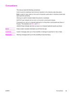 5
5 -
 6
6 -
 7
7 -
8
-
9
-
10
-
11
-
12
-
13
-
14
-
15
-
16
-
17
-
18
-
19
-
20
-
21
-
22
-
23
-
24
-
25
-
26
-
27
-
28
-
29
-
30
-
31
-
32
-
33
-
34
-
35
-
36
-
37
-
38
-
39
-
40
-
41
-
42
-
43
-
44
-
45
-
46
-
47
-
48
-
49
-
50
-
51
-
52
-
53
-
54
-
55
-
56
-
57
-
58
-
59
-
60
-
61
-
62
-
63
-
64
-
65
-
66
-
67
-
68
-
69
-
70
-
71
-
72
-
73
-
74
-
75
-
76
-
77
-
78
-
79
-
80
-
81
-
82
-
83
-
84
-
85
-
86
-
87
-
88
-
89
-
90
-
91
-
92
-
93
-
94
-
95
-
96
-
97
-
98
-
99
-
100
-
101
-
102
-
103
-
104
-
105
-
106
-
107
-
108
-
109
-
110
-
111
-
112
-
113
-
114
-
115
-
116
-
117
-
118
-
119
-
120
-
121
-
122
-
123
-
124
-
125
-
126
-
127
-
128
-
129
-
130
-
131
-
132
-
133
-
134
-
135
-
136
-
137
-
138
-
139
-
140
-
141
-
142
-
143
-
144
-
145
-
146
-
147
-
148
-
149
-
150
-
151
-
152
-
153
-
154
-
155
-
156
-
157
-
158
-
159
-
160
-
161
-
162
-
163
-
164
-
165
-
166
-
167
-
168
-
169
-
170
-
171
-
172
-
173
-
174
-
175
-
176
-
177
-
178
-
179
-
180
-
181
-
182
-
183
-
184
-
185
-
186
-
187
-
188
-
189
-
190
-
191
-
192
-
193
-
194
-
195
-
196
-
197
-
198
-
199
-
200
-
201
-
202
-
203
-
204
-
205
-
206
-
207
-
208
-
209
-
210
-
211
-
212
-
213
-
214
-
215
-
216
-
217
-
218
-
219
-
220
-
221
-
222
-
223
-
224
-
225
-
226
-
227
-
228
-
229
-
230
-
231
-
232
-
233
-
234
-
235
-
236
-
237
-
238
-
239
-
240
-
241
-
242
-
243
-
244
-
245
-
246
-
247
-
248
-
249
-
250
-
251
-
252
-
253
-
254
-
255
-
256
-
257
-
258
-
259
-
260
-
261
-
262
-
263
-
264
-
265
-
266
-
267
-
268
-
269
-
270
-
271
-
272
-
273
-
274
-
275
-
276
-
277
-
278
-
279
-
280
-
281
-
282
-
283
-
284
-
285
-
286
-
287
-
288
-
289
-
290
-
291
-
292
-
293
-
294
-
295
-
296
-
297
-
298
-
299
-
300
-
301
-
302
-
303
-
304
-
305
-
306
-
307
-
308
-
309
-
310
-
311
-
312
-
313
-
314
-
315
-
316
-
317
-
318
-
319
-
320
-
321
-
322
-
323
-
324
-
325
-
326
-
327
-
328
-
329
-
330
-
331
-
332
-
333
-
334
-
335
-
336
-
337
-
338
-
339
-
340
-
341
-
342
-
343
-
344
-
345
-
346
-
347
-
348
-
349
-
350
-
351
-
352
-
353
-
354
-
355
-
356
-
357
-
358
-
359
-
360
-
361
-
362
-
363
-
364
-
365
-
366
-
367
-
368
-
369
-
370
-
371
-
372
-
373
-
374
-
375
-
376
-
377
-
378
-
379
-
380
-
381
-
382
-
383
-
384
-
385
-
386
-
387
-
388
-
389
-
390
-
391
-
392
-
393
-
394
-
395
-
396
-
397
-
398
-
399
-
400
-
401
-
402
-
403
-
404
-
405
-
406
-
407
-
408
-
409
-
410
-
411
-
412
-
413
-
414
-
415
-
416
-
417
-
418
-
419
-
420
-
421
-
422
-
423
-
424
-
425
-
426
-
427
-
428
-
429
-
430
-
431
-
432
-
433
-
434
-
435
-
436
-
437
-
438
-
439
-
440
-
441
-
442
-
443
-
444
-
445
-
446
-
447
-
448
-
449
-
450
-
451
-
452
-
453
-
454
-
455
-
456
-
457
-
458
-
459
-
460
-
461
-
462
-
463
-
464
-
465
-
466
-
467
-
468
-
469
-
470
-
471
-
472
-
473
-
474
-
475
-
476
-
477
-
478
-
479
-
480
-
481
-
482
-
483
-
484
-
485
-
486
-
487
-
488
-
489
-
490
-
491
-
492
-
493
-
494
-
495
-
496
-
497
-
498
-
499
-
500
-
501
-
502
-
503
-
504
-
505
-
506
-
507
-
508
-
509
-
510
-
511
-
512
-
513
-
514
-
515
-
516
-
517
-
518
-
519
-
520
-
521
-
522
-
523
-
524
-
525
-
526
-
527
-
528
-
529
-
530
-
531
-
532
-
533
-
534
-
535
-
536
-
537
-
538
-
539
-
540
-
541
-
542
-
543
-
544
-
545
-
546
-
547
-
548
-
549
-
550
-
551
-
552
-
553
-
554
-
555
-
556
-
557
-
558
-
559
-
560
-
561
-
562
-
563
-
564
-
565
-
566
-
567
-
568
-
569
-
570
-
571
-
572
-
573
-
574
-
575
-
576
-
577
-
578
-
579
-
580
-
581
-
582
-
583
-
584
-
585
-
586
-
587
-
588
-
589
-
590
-
591
-
592
-
593
-
594
-
595
-
596
-
597
-
598
 |
 |

hp
color LaserJet
3500/3550 and 3700
series printer
service