HP 3PAR StoreServ 7400 4-node HP 3PAR StoreServ 7000 Storage Installation Guid
HP 3PAR StoreServ 7400 4-node Manual
 |
View all HP 3PAR StoreServ 7400 4-node manuals
Add to My Manuals
Save this manual to your list of manuals |
HP 3PAR StoreServ 7400 4-node manual content summary:
- HP 3PAR StoreServ 7400 4-node | HP 3PAR StoreServ 7000 Storage Installation Guid - Page 1
HP 3PAR StoreServ 7000 Storage nl Installation Guide Abstract This guide is designed to instruct qualified technicians who are authorized to install the HP 3PAR StoreServ 7000 Storage system and associated hardware components. HP Part Number: QR482-96436 Published: August 2013 Edition: 1 - HP 3PAR StoreServ 7400 4-node | HP 3PAR StoreServ 7000 Storage Installation Guid - Page 2
to change without notice. The only warranties for HP products and services are set forth in the express warranty statements accompanying such products and services. Nothing herein should be construed as constituting an additional warranty. HP shall not be liable for technical or editorial errors - HP 3PAR StoreServ 7400 4-node | HP 3PAR StoreServ 7000 Storage Installation Guid - Page 3
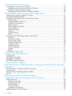
...7 Redeeming and Registering HP 3PAR Licenses 8 Storage System Installation...8 Storage System Hardware Installation Checklist 8 2 Identifying Storage System Components 9 Understanding Component Numbering 9 Disk Drive Numbering...9 Controller Nodes...10 Controller Node PCIe Slots and Ports - HP 3PAR StoreServ 7400 4-node | HP 3PAR StoreServ 7000 Storage Installation Guid - Page 4
System Tasks...73 9 Support and Other Resources 74 Contacting HP...74 HP 3PAR documentation...74 Typographic conventions...77 HP 3PAR branding information 77 10 Documentation feedback 78 A HP 3PAR StoreServ 7000 (Controller and Storage) and M6700 Series (Storage) Contents List 79 HP 3PAR - HP 3PAR StoreServ 7400 4-node | HP 3PAR StoreServ 7000 Storage Installation Guid - Page 5
HP 3PAR Storage Software When HP 3PAR SmartStart is Unavailable 92 Launching the SP Setup Wizard 92 Launching the Storage System Setup Wizard 92 Installing the Management Console When HP 3PAR SmartStart is Unavailable 92 E Validating Remote Support 93 F Troubleshooting 95 Troubleshooting - HP 3PAR StoreServ 7400 4-node | HP 3PAR StoreServ 7000 Storage Installation Guid - Page 6
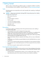
HP Support or visit http://www.hp.com/support. Tools The following tools are not required but can be useful, especially when unpacking or installing the storage system when installing or servicing the storage system: • Using improper tools can result in damage to the storage system. • Prepare an - HP 3PAR StoreServ 7400 4-node | HP 3PAR StoreServ 7000 Storage Installation Guid - Page 7
service tools. Racks Ensure that precautions have been taken to ensure rack stability and safety. Observe all cautions and warnings included in the installation instructions on the equipment. Ensure that the equipment is properly supported and braced when installing options and boards. • Be - HP 3PAR StoreServ 7400 4-node | HP 3PAR StoreServ 7000 Storage Installation Guid - Page 8
in a third-party rack or HP rack. See "Installing Storage System Components into a Rack" (page 19). See the HP 3PAR StoreServ 7000 Storage Site Planning Manual for configuration specifications and installation requirements. For information about supported hardware and software platforms, visit the - HP 3PAR StoreServ 7400 4-node | HP 3PAR StoreServ 7000 Storage Installation Guid - Page 9
The storage system can include the following types of drive and node enclosures: • The HP M6710 to the 4U24 drive enclosure. • The HP 3PAR StoreServ 7200 and 7400 controller enclosures hold up to 24, 2.5 number of supported drive enclosures varies based on the model and the number of nodes. Disk - HP 3PAR StoreServ 7400 4-node | HP 3PAR StoreServ 7000 Storage Installation Guid - Page 10
, virtualized view of the system. Controller nodes are located in the rear of the node enclosure. The HP 3PAR StoreServ 7200 Storage system contains two nodes: node 0 and node 1. The HP 3PAR StoreServ 7400 Storage system can contain two nodes or four nodes: node 0 and node 1 in the lower controller - HP 3PAR StoreServ 7400 4-node | HP 3PAR StoreServ 7000 Storage Installation Guid - Page 11
and Ports Table 1 (page 11) describes default configurations for the HP 3PAR StoreServ 7000 Storage system: Table 1 Storage System Expansion Cards Expansion cards 2 FC HBAs only 2 10 Gb/s converged network adapter (CNA) only 2 FC HBAs + 2 10 Gb/s CNAs Nodes 0 and 1 1 FC HBA each 1 10 Gb/s CNA each - HP 3PAR StoreServ 7400 4-node | HP 3PAR StoreServ 7000 Storage Installation Guid - Page 12
battery. The PCMs are located at the rear of the storage system, and on the sides of the enclosure. There are two PCMs per enclosure. The PCMs are numbered 0 and 1 from left to right. Figure 8 PCM Numbering for HP 3PAR 7200 (2U) Controller Node Enclosure 12 Identifying Storage System Components - HP 3PAR StoreServ 7400 4-node | HP 3PAR StoreServ 7000 Storage Installation Guid - Page 13
13) and Figure 11 (page 13)). Figure 10 PCM Numbering for HP M6710 Figure 11 PCM Numbering for HP M6720 Service Processor The HP 3PAR StoreServ 7000 Storage system can include an HP 3PAR Service Processor (SP) or a Virtual Service Processor (VSP). If your configuration includes an SP, it is located - HP 3PAR StoreServ 7400 4-node | HP 3PAR StoreServ 7000 Storage Installation Guid - Page 14
. Make sure there is enough clearance for service. For example, the PDUs mounted vertically at the back of a rack must have enough clearance to remove node and drive chassis power supples. NOTE: Depending on the configuration, PDUs can be mounted vertically. 14 Identifying Storage System Components - HP 3PAR StoreServ 7400 4-node | HP 3PAR StoreServ 7000 Storage Installation Guid - Page 15
storage system, ensure all requirements documented in the HP 3PAR StoreServ 7000 Storage Site Planning Manual have been met. WARNING! Do not use this procedure if you are installing storage system front of the storage system. 4. Remove the rack from the container. 5. Carefully guide the rack down - HP 3PAR StoreServ 7400 4-node | HP 3PAR StoreServ 7000 Storage Installation Guid - Page 16
-node 7400 system, two cable management brackets have Velcro straps to hold the cables. You can remove and discard these brackets, but HP recommends support the connected data cables and connectors during transport. HP recommends installing the brackets before transporting the system Storage System - HP 3PAR StoreServ 7400 4-node | HP 3PAR StoreServ 7000 Storage Installation Guid - Page 17
(see Figure 15 (page 17)). NOTE: Make sure the brackets are aligned and leveled with the link connectors before tightening the captive screws. HP recommends tightening the screws to 19 in-lbs. Figure 15 Tightening the Captive Screws Installing and Removing the Cable Restraint Shipping Brackets 17 - HP 3PAR StoreServ 7400 4-node | HP 3PAR StoreServ 7000 Storage Installation Guid - Page 18
3. Remove the brackets. Be careful not to damage the attached data cables. Now continue on to"Verifying Setup and Powering On the Storage System" (page 37) and verify setup before powering on the storage system and initializing the SP and storage system software. 18 Setting Up a Factory-Integrated - HP 3PAR StoreServ 7400 4-node | HP 3PAR StoreServ 7000 Storage Installation Guid - Page 19
HP 3PAR StoreServ 7000 Storage Site Planning Manual have been met. Follow these procedures if you are installing any of the following storage system components in an existing or partially populated rack: • PCIe adapters • Disk Drive enclosures • Controller node installation instructions support - HP 3PAR StoreServ 7400 4-node | HP 3PAR StoreServ 7000 Storage Installation Guid - Page 20
screws (two in front, two in back) in the top and bottom holes. Tighten the shoulder screws with a torque of 19 in-lbs. 20 Installing Storage System Components into a Rack - HP 3PAR StoreServ 7400 4-node | HP 3PAR StoreServ 7000 Storage Installation Guid - Page 21
bracket holes with the top holes of the rail(s). The orientation of the middle support bracket is neutral. b. Insert and tighten screws. Figure 18 Installing the Middle Support Bracket 6. Repeat steps 1 through 5 for the other rail. 7. Snap one cage nut into the rack hole two positions above the - HP 3PAR StoreServ 7400 4-node | HP 3PAR StoreServ 7000 Storage Installation Guid - Page 22
nodes to host computers and disk drives. Installing or upgrading PCle adapters involves adding additional supported types of adapters or replacing existing adapters. WARNING! Fibre Channel HBA and iSCSI CNA upgrades on the HP 3PAR StoreServ 7400 Storage system must be serviced by authorized service - HP 3PAR StoreServ 7400 4-node | HP 3PAR StoreServ 7000 Storage Installation Guid - Page 23
the enclosure is oriented correctly by looking at the rear of the enclosure. Verify the node numbering by reviewing the controller node label on both edges of the enclosure slot. Figure 20 Verify Controller Node Numbering 2. At the front of the enclosure, remove the yellow bezels on each side of - HP 3PAR StoreServ 7400 4-node | HP 3PAR StoreServ 7000 Storage Installation Guid - Page 24
is to add the same number of identical drives to every HP M6720 Drive Enclosure in the system, with a minimum of two drives added to each LFF chassis. The minimum supported upgrade for a 7400 with one or more expansion HP M6720 Drive Enclosures is two identical drives added to adjacent slots in - HP 3PAR StoreServ 7400 4-node | HP 3PAR StoreServ 7000 Storage Installation Guid - Page 25
LFF disk drives) In a storage system with mixed HP M6710 and M6720 Drive Enclosures there above for SFF and LFF drives. WARNING! If the StoreServ is enabled with the Data-at-Rest (DAR) encryption beginning this procedure, review how to load the drives based on drive type, speed, and capacity. See " - HP 3PAR StoreServ 7400 4-node | HP 3PAR StoreServ 7000 Storage Installation Guid - Page 26
the left, and slide it into the enclosure. 3. Push firmly until the handle fully engages and clicks. Figure 25 Installing a 3.5 inch disk drive 26 Installing Storage System Components into a Rack - HP 3PAR StoreServ 7400 4-node | HP 3PAR StoreServ 7000 Storage Installation Guid - Page 27
Installing the Service Processor in the Storage System The HP 3PAR Service Processor consists of the following: • A standard HP Server • A 1U Rail Kit for that specific server NOTE: The SP ID is the HP 7-digit serial number of the array located on the top front of the server and in a pull-out - HP 3PAR StoreServ 7400 4-node | HP 3PAR StoreServ 7000 Storage Installation Guid - Page 28
Figure 26 Rail Kit Components In addition to the supplied items, you may also need the following: • Screws fitting a threaded-hole rack • Screwdriver • Optional cable management arm (see Figure 27 (page 29)) 28 Installing Storage System Components into a Rack - HP 3PAR StoreServ 7400 4-node | HP 3PAR StoreServ 7000 Storage Installation Guid - Page 29
. See HP 3PAR StoreServ 7000/7450 Cabling Configuration Guide for the best practices for node and drive enclosure positioning in specific configurations. To install the rail kit and service processor: mounting pins on the rear of each rail. Installing the Service Processor in the Storage System 29 - HP 3PAR StoreServ 7400 4-node | HP 3PAR StoreServ 7000 Storage Installation Guid - Page 30
Figure 28 Installing Cage Nuts and Rail Mounting Pins 3. Align the mounting rail with the cage nuts, and fasten the mounting rails to the rack with the proper screws. 30 Installing Storage System Components into a Rack - HP 3PAR StoreServ 7400 4-node | HP 3PAR StoreServ 7000 Storage Installation Guid - Page 31
mounting rail. WARNING! To prevent the risk of injury or equipment damage, inspect the rack to ensure that it is adequately stabilized before installing the service processor. Installing the Service Processor in the Storage System 31 - HP 3PAR StoreServ 7400 4-node | HP 3PAR StoreServ 7000 Storage Installation Guid - Page 32
by aligning each side rail to the component, and then snapping it into place. Figure 30 Installing the Service Processor 6. Slide the service processor onto the mounting rails and into the rack. Figure 31 Sliding the Service Processor into the Rack 32 Installing Storage System Components into a Rack - HP 3PAR StoreServ 7400 4-node | HP 3PAR StoreServ 7000 Storage Installation Guid - Page 33
7. Fasten the service processor to the rack. 8. (Optional) Install the cable management arm. See the instructions provided in the kit. 9. Use the straps extends from the component. Continue on to "Cabling the Storage System" (page 34). Installing the Service Processor in the Storage System 33 - HP 3PAR StoreServ 7400 4-node | HP 3PAR StoreServ 7000 Storage Installation Guid - Page 34
to cable the system, visit www.hp.com/go/3par. Scroll to Support, and click HP 3PAR StoreServ 7000 Support and then Manuals. Then scroll to Setup and install - general and select the specific HP 3PAR StoreServ 7000 Storage Cabling Configuration Guide. Cabling Controller Nodes Nodes are numbered 0 to - HP 3PAR StoreServ 7400 4-node | HP 3PAR StoreServ 7000 Storage Installation Guid - Page 35
computer to a controller node. HP recommends separate connections from each host computer to each of the controller nodes in the storage system, with connections distributed evenly across all nodes. Table 6 (page 35) describes the maximum supported Fibre Channel cable length based on the cable size - HP 3PAR StoreServ 7400 4-node | HP 3PAR StoreServ 7000 Storage Installation Guid - Page 36
at the bottom of the rack. Each PDU AC cord connects to the appropriate outlet based on the type of cord and power requirements to supply power to the storage system. To access the vertically mounted PDUs or servicing area, the PDUs can be lowered out of the rack. 1. Remove the two top mounting - HP 3PAR StoreServ 7400 4-node | HP 3PAR StoreServ 7000 Storage Installation Guid - Page 37
PDUs, and adheres to the guidelines described in HP 3PAR StoreServ 7000 Storage Site Planning Manual. Power Cord Connections Each storage system arrives with all internal power cords configured and connected. Before powering on the storage system, verify the following: • The AC cords are correctly - HP 3PAR StoreServ 7400 4-node | HP 3PAR StoreServ 7000 Storage Installation Guid - Page 38
fully evaporate before completing the power-on sequence. Powering On the Storage System 1. Set the circuit breakers on the PDUs to the ON service processor. 4. Power on the drive enclosure PCMs. 5. Power on the node enclosure PCMs. 6. After approximately 10 minutes, allowing time for the system - HP 3PAR StoreServ 7400 4-node | HP 3PAR StoreServ 7000 Storage Installation Guid - Page 39
Verifying LED Status 1. At the front of the storage system, verify the bezel and disk drive LEDs are illuminating green. NOTE: If any module fault or disk drive LEDs are not green, do not proceed until the problem is resolved. Figure 35 Bezel LEDs Table 7 Identifying Bezel LEDs Item 1 2 3 - HP 3PAR StoreServ 7400 4-node | HP 3PAR StoreServ 7000 Storage Installation Guid - Page 40
Figure 36 Disk Drive LEDs Table 8 Identifying Disk Drive LEDs Item 1 2 Description Amber LED indicates a fault. Green LED indicates the system is ready. 40 Verifying Setup and Powering On the Storage System - HP 3PAR StoreServ 7400 4-node | HP 3PAR StoreServ 7000 Storage Installation Guid - Page 41
be blinking green once per second. The green LED of each node will blink together when the storage cluster is properly formed. Figure 37 Node Enclosure PCM LEDs Figure 38 Controller Node LEDs NOTE: The figure shows an HP 3PAR 7200 controller node as an example. NOTE: The batteries are fully charged - HP 3PAR StoreServ 7400 4-node | HP 3PAR StoreServ 7000 Storage Installation Guid - Page 42
interconnect ports are used only with 7400 4-Node systems. Figure 39 7400 4-Node LEDs Table 9 Node Interconnect Ports LEDs Item Description link cabling error • Controller node in wrong slot • Serial number mismatch between controller nodes 42 Verifying Setup and Powering On the Storage System - HP 3PAR StoreServ 7400 4-node | HP 3PAR StoreServ 7000 Storage Installation Guid - Page 43
Drive Enclosure LEDs Figure 40 Drive Enclosure PCM LEDs CAUTION: Do not proceed without first correcting all fault indications (except for PCM batteries). The cluster is not formed until the storage system software installation has been performed. Verifying LED Status 43 - HP 3PAR StoreServ 7400 4-node | HP 3PAR StoreServ 7000 Storage Installation Guid - Page 44
Identifying Service Processor LEDs The HP 3PAR SP (Proliant DL320e) LEDs are located at the front and rear of the SP. Figure 41 Front Panel LEDs Table 10 Front panel LEDs Item LED 1 UID LED/button 2 Power On/Standby button and system power Appearance Blue Flashing Blue Off Green Flashing Green - HP 3PAR StoreServ 7400 4-node | HP 3PAR StoreServ 7000 Storage Installation Guid - Page 45
applicable to Off your system (for hot-plug HP CS power supplies ONLY) Description Link No link Activity No activity Active System is being managed remotely Indicator Status in the HP 3PAR StoreServ 7000 Storage Service Guide. Continue on to "Initializing the Service Processor" (page 46). Verifying - HP 3PAR StoreServ 7400 4-node | HP 3PAR StoreServ 7000 Storage Installation Guid - Page 46
all actions required for maintenance of the storage system. The service processor provides real-time, automated monitoring and remote access to HP 3PAR Support in order to diagnose and resolve potential problems. An HP 3PAR StoreServ system can include either a virtual or physical SP. Use the - HP 3PAR StoreServ 7400 4-node | HP 3PAR StoreServ 7000 Storage Installation Guid - Page 47
on to "Setting Up the Service Processor and Storage System" (page 51) to set up the VSP with SmartStart over the public network. If you are not using SmartStart, see "Installing HP 3PAR Storage Software When HP 3PAR SmartStart is Unavailable" (page 92) to manually launch the setup wizards. Option - HP 3PAR StoreServ 7400 4-node | HP 3PAR StoreServ 7000 Storage Installation Guid - Page 48
the cursor. 10. Continue on to "Setting Up the Service Processor and Storage System" (page 51) to set up the VSP with SmartStart over the public network. If you are not using SmartStart, see "Installing HP 3PAR Storage Software When HP 3PAR SmartStart is Unavailable" (page 92). NOTE: This network - HP 3PAR StoreServ 7400 4-node | HP 3PAR StoreServ 7000 Storage Installation Guid - Page 49
https://192.168.0.100/sp/SetIpAddress.html. 5. Log in with the user ID setupusr and no password. The Service Processor IP Setup wizard is displayed. NOTE: The Service Processor Setup Wizard may not display correctly when using Microsoft Internet Explorer 10 with default security settings. If the - HP 3PAR StoreServ 7400 4-node | HP 3PAR StoreServ 7000 Storage Installation Guid - Page 50
customer LAN. 11. Continue on to "Setting Up the Service Processor and Storage System" (page 51) and set up the SP with SmartStart over the public network. If you are not using SmartStart, see "Installing HP 3PAR Storage Software When HP 3PAR SmartStart is Unavailable" (page 92). 50 Initializing the - HP 3PAR StoreServ 7400 4-node | HP 3PAR StoreServ 7000 Storage Installation Guid - Page 51
is established. Table 12 SP and Storage System Software Installation Checklist HP 3PAR Service Processor StoreServ serial number NOTE: The StoreServ 7-digit serial number is located on the back of your HP 3PAR storage system next to the power switch for the node enclosure PCM, and it begins with16 - HP 3PAR StoreServ 7400 4-node | HP 3PAR StoreServ 7000 Storage Installation Guid - Page 52
equal (=), and forward slash (/). HP 3PAR Storage System StoreServ serial number NOTE: The serial number is located on the back of your HP 3PAR storage system next to the power switch for the node enclosure PCM, and it begins with16 (for example, 1624635). StoreServ system name IP address (IPv4 only - HP 3PAR StoreServ 7400 4-node | HP 3PAR StoreServ 7000 Storage Installation Guid - Page 53
with the HP 3PAR Service Processor Setup Wizard • Setting up the storage system with the HP 3PAR Storage System Setup Wizard You only need to set up the SP and StoreServ system only once for each new storage system. Before inserting the HP 3PAR SmartStart CD, the following system requirements must - HP 3PAR StoreServ 7400 4-node | HP 3PAR StoreServ 7000 Storage Installation Guid - Page 54
set up the SP. Follow the instructions on each screen, and then click Next. The setup takes about 15 minutes. You must have the following information: • StoreServ 7-digit serial number • SP network configuration: ◦ The name to be assigned to the Service Processor ◦ IP address (IPv4 only) ◦ Subnet - HP 3PAR StoreServ 7400 4-node | HP 3PAR StoreServ 7000 Storage Installation Guid - Page 55
ID to retrieve the SP ID. After the SP ID is generated, click Next. NOTE: he StoreServ 7-digit serial number is located on the back of your HP 3PAR storage system next to the power switch for the node enclosure PCM, and it begins with16 (for example, 1624635). NOTE: During the SP Setup process, the - HP 3PAR StoreServ 7400 4-node | HP 3PAR StoreServ 7000 Storage Installation Guid - Page 56
the completed installation checklist from HP 3PAR StoreServ 7000 Site Planning Manual as reference. NOTE: For additional information and help, use the HP 3PAR SmartStart online help (accessible by pressing F1). 1. Enter the SP information for the following fields: • Service Processor hostname • IP - HP 3PAR StoreServ 7400 4-node | HP 3PAR StoreServ 7000 Storage Installation Guid - Page 57
your storage system, including the following: • Timely remote service • Remote online software updates • Accelerated troubleshooting and issue resolution Remote Support sends diagnostic information, such as system health statistics, configuration data, performance data, and system events, to HP 3PAR - HP 3PAR StoreServ 7400 4-node | HP 3PAR StoreServ 7000 Storage Installation Guid - Page 58
be opened (outbound) between Service Processor IP and the following IP addresses: • 15.201.200.205 g4t2481g.houston.hp.com • 15.201.200.206 g4t2482g.houston.hp.com • 15.240.0.73 g9t1615g.houston.hp.com • 15.240.0.74 g9t1616g.houston.hp.com NOTE: If the StoreServ Storage system or the SP are placed - HP 3PAR StoreServ 7400 4-node | HP 3PAR StoreServ 7000 Storage Installation Guid - Page 59
wizard enables Remote Support upon completion. Figure 50 Remote Support Page System Support Information To receive remote technical support: 1. Enter the Phone number • Fax number • Email address for service alert notification 3. Click Next. Launching the HP 3PAR Service Processor Setup Wizard 59 - HP 3PAR StoreServ 7400 4-node | HP 3PAR StoreServ 7000 Storage Installation Guid - Page 60
Figure 51 System Support Information Page Time and Region On the Time and Region page, the Manual option is selected and automatically populated with the current host Web browser and Pacific) and the city or country closest to you. Click Next. 60 Setting Up the Service Processor and Storage System - HP 3PAR StoreServ 7400 4-node | HP 3PAR StoreServ 7000 Storage Installation Guid - Page 61
on assigning these passwords, see your completed Storage System Software Installation checklist. NOTE: To reset a password for the SP, log into SPOCC. If you lose all your SP passwords and are unable to log into SPOCC, you must re-image the SP. Launching the HP 3PAR Service Processor Setup Wizard 61 - HP 3PAR StoreServ 7400 4-node | HP 3PAR StoreServ 7000 Storage Installation Guid - Page 62
Figure 53 Change Passwords Page 62 Setting Up the Service Processor and Storage System - HP 3PAR StoreServ 7400 4-node | HP 3PAR StoreServ 7000 Storage Installation Guid - Page 63
status. The arrows indicate the operation is in progress, and the check marks indicate the operation is complete. Click OK to finish setting up the Service Processor. Launching the HP 3PAR Service Processor Setup Wizard 63 - HP 3PAR StoreServ 7400 4-node | HP 3PAR StoreServ 7000 Storage Installation Guid - Page 64
Figure 55 Apply Settings Finish The Finish page describes the status of the SP setup. Click Finish. Figure 56 SP Setup Finish Page 64 Setting Up the Service Processor and Storage System - HP 3PAR StoreServ 7400 4-node | HP 3PAR StoreServ 7000 Storage Installation Guid - Page 65
Launching the HP 3PAR Storage System Setup Wizard The setup wizard proceeds through the following steps: • Welcome • Enter Storage System • Verify Storage System • Configure Networking • Configure Time • Change Password • Verify Configuration • Progress • Results To launch the storage system setup - HP 3PAR StoreServ 7400 4-node | HP 3PAR StoreServ 7000 Storage Installation Guid - Page 66
wizard and set up the SP. Follow the instructions on each page, and then click Next. You must have the following information before you proceed: • The 7-digit HP 3PAR storage system serial number • Storage system name • Storage system networking information: ◦ IP address (IPv4 only) ◦ Subnet mask - HP 3PAR StoreServ 7400 4-node | HP 3PAR StoreServ 7000 Storage Installation Guid - Page 67
the location of the serial number which is situated on the side of the right rear node enclosure PCM and adjacent to the power switch. The serial number begins with 16 (for example, serial number: 1624635). Figure 60 Serial Number Label Locations Launching the HP 3PAR Storage System Setup Wizard 67 - HP 3PAR StoreServ 7400 4-node | HP 3PAR StoreServ 7000 Storage Installation Guid - Page 68
, and then click Next. Figure 61 Verify Storage System Page Configure Networking On the Configure Networking page, complete the required fields and click Next. • Storage System Name • IPv4 Configuration ◦ IPv4 Address ◦ Subnet Mask ◦ Gateway 68 Setting Up the Service Processor and Storage System - HP 3PAR StoreServ 7400 4-node | HP 3PAR StoreServ 7000 Storage Installation Guid - Page 69
you want to manually enter the date and time. If you select Automatic, complete the NTP Server field and click Test to get the specified NTP time. In the Time Zone section, select the appropriate region. Click Next. Figure 63 Configure Time Page Launching the HP 3PAR Storage System Setup Wizard 69 - HP 3PAR StoreServ 7400 4-node | HP 3PAR StoreServ 7000 Storage Installation Guid - Page 70
Change Password This login profile is used to add this storage system to the Service Processor and for initial administrative access to the storage system. When updating of password is complete, click Next. NOTE: Passwords for the 3paradm username can include all printable characters and be between - HP 3PAR StoreServ 7400 4-node | HP 3PAR StoreServ 7000 Storage Installation Guid - Page 71
operation status. The arrows indicate the operation is in progress, and the check marks indicate the operation is complete. NOTE: Depending on the type of system configuration, the operation may take to 30 minutes or longer to complete. Launching the HP 3PAR Storage System Setup Wizard 71 - HP 3PAR StoreServ 7400 4-node | HP 3PAR StoreServ 7000 Storage Installation Guid - Page 72
Figure 66 Progress Page Results The Results page confirms the storage system is ready to use. Click Finish. Figure 67 Results Page 72 Setting Up the Service Processor and Storage System - HP 3PAR StoreServ 7400 4-node | HP 3PAR StoreServ 7000 Storage Installation Guid - Page 73
, see HP 3PAR StoreServ 7000 Storage SmartStart Software User's Guide. • Creating LUNs and using the StoreServ For more information, see HP 3PAR Management Console User Guide. For additional support and other resources, see "Support and Other Resources" (page 74) Post-Installation System Tasks 73 - HP 3PAR StoreServ 7400 4-node | HP 3PAR StoreServ 7000 Storage Installation Guid - Page 74
of support you are requesting: HP 3PAR storage system HP 3PAR StoreServ 7200, 7400, and 7450 Storage systems HP 3PAR StoreServ 10000 Storage systems HP 3PAR T-Class storage systems HP 3PAR F-Class storage systems Support request StoreServ 7000 Storage 3PAR or 3PAR Storage HP 3PAR documentation - HP 3PAR StoreServ 7400 4-node | HP 3PAR StoreServ 7000 Storage Installation Guid - Page 75
and manage HP 3PAR Remote Copy HP 3PAR Remote Copy Software User's Guide Updating HP 3PAR operating systems HP 3PAR Upgrade Pre-Planning Guide Identifying storage system components, troubleshooting information, and detailed alert information HP 3PAR F-Class, T-Class, and StoreServ 10000 Storage - HP 3PAR StoreServ 7400 4-node | HP 3PAR StoreServ 7000 Storage Installation Guid - Page 76
3PAR StoreServ 7000 Storage Service Guide HP 3PAR StoreServ 7450 Storage Service Guide Troubleshooting 7200, 7400, and 7450 storage systems HP 3PAR StoreServ 7000 Storage Troubleshooting Guide HP 3PAR StoreServ 7450 Storage Troubleshooting Guide Maintaining the Service Processor HP 3PAR Service - HP 3PAR StoreServ 7400 4-node | HP 3PAR StoreServ 7000 Storage Installation Guid - Page 77
in order to achieve a functional and supported implementation based on testing at HP. HP 3PAR branding information • The server previously referred to as the "InServ" is now referred to as the "HP 3PAR StoreServ Storage system." • The operating system previously referred to as the "InForm OS - HP 3PAR StoreServ 7400 4-node | HP 3PAR StoreServ 7000 Storage Installation Guid - Page 78
documentation that meets your needs. To help us improve the documentation, send any errors, suggestions, or comments to Documentation Feedback ([email protected]). Include the document title and part number, version number, or the URL when submitting your feedback. 78 Documentation feedback - HP 3PAR StoreServ 7400 4-node | HP 3PAR StoreServ 7000 Storage Installation Guid - Page 79
A HP 3PAR StoreServ 7000 (Controller and Storage) and M6700 Series (Storage) Contents List The following components may vary, depending on system configuration: • Appearance of components • Quantity of components • Whether or not the component is included with the system HP 3PAR StoreServ 7000 and - HP 3PAR StoreServ 7400 4-node | HP 3PAR StoreServ 7000 Storage Installation Guid - Page 80
Figure 70 7000 Series Controller Figure 71 M6700 Series I/O Module Figure 72 7000 Series PCM 80 HP 3PAR StoreServ 7000 (Controller and Storage) and M6700 Series (Storage) Contents List - HP 3PAR StoreServ 7400 4-node | HP 3PAR StoreServ 7000 Storage Installation Guid - Page 81
Figure 73 M6700 Series PCM Figure 74 SFF Drive Assembly Blank Figure 75 SFF Drive Assembly HP 3PAR StoreServ 7000 and M6700 Components 81 - HP 3PAR StoreServ 7400 4-node | HP 3PAR StoreServ 7000 Storage Installation Guid - Page 82
Figure 76 LFF Drive Assembly Blank Figure 77 LFF Drive Assembly Figure 78 7000 Series Battery (Installed in 7000 Series PCM) 82 HP 3PAR StoreServ 7000 (Controller and Storage) and M6700 Series (Storage) Contents List - HP 3PAR StoreServ 7400 4-node | HP 3PAR StoreServ 7000 Storage Installation Guid - Page 83
Accessory Kits The following accessory kits can be included with your system: • Power cords • SAS cables • Cable bundle ties • Hook and Node CSR and HBA CSU limitations • 1U filler panels • Link cables • Shipping bracket kit Service Processor Field Replaceable Unit (FRU) Figure 79 Service Processor - HP 3PAR StoreServ 7400 4-node | HP 3PAR StoreServ 7000 Storage Installation Guid - Page 84
) Figure 81 Right and Left 4U Rail Subassembly (Right Subassembly Shown) Figure 82 M5 Shoulder Screw for Rack Mount Figure 83 M5 Screw for Middle Support Bracket 84 HP 3PAR StoreServ 7000 (Controller and Storage) and M6700 Series (Storage) Contents List - HP 3PAR StoreServ 7400 4-node | HP 3PAR StoreServ 7000 Storage Installation Guid - Page 85
Figure 84 Middle Support Bracket Figure 85 M5 Cage Nut Rail Kits 85 - HP 3PAR StoreServ 7400 4-node | HP 3PAR StoreServ 7000 Storage Installation Guid - Page 86
with Data Encryption HP 3PAR Data Encryption security feature allows you to encrypt all specifically formatted hard drives on the storage system with an authentication key and the use of Self Encrypting Drives (SEDs). When a Data Encryption license is registered, you must manually enable the - HP 3PAR StoreServ 7400 4-node | HP 3PAR StoreServ 7000 Storage Installation Guid - Page 87
Adding Disk Drives and Expansion Drive Enclosures HP 3PAR StoreServ 7000 products include 3PAR licensing that enables all functionality associated with the system. A failure to register the license key may limit access and restrict upgrading of your system. Before you proceed with upgrading, verify - HP 3PAR StoreServ 7400 4-node | HP 3PAR StoreServ 7000 Storage Installation Guid - Page 88
the expected service life of an HP 3PAR StoreServ under the great majority of configurations, IO patterns, and workloads. HP 3PAR StoreServ tracks all HP support contracts. • The first expansion drive enclosure added to a system must be populated with the same number of disk drives as the node - HP 3PAR StoreServ 7400 4-node | HP 3PAR StoreServ 7000 Storage Installation Guid - Page 89
adding hard drives: • Checking initial status • Inserting hard drives • Checking status • Checking progress • Completing the upgrade Checking Initial Status Under Systems, select Physical Disks, and in the right pane, select the Physical Disks tab. Figure 88 Physical Disks Tab Inserting Disk Drives - HP 3PAR StoreServ 7400 4-node | HP 3PAR StoreServ 7000 Storage Installation Guid - Page 90
to ready for use. Output indicates that each of the six added disk drives still have normal and spare chunklets to be initialized. NOTE: The system can be used normally, but newly added capacity must be initialized before it can be allocated. Checking Progress On the Physical Disks tab, in the - HP 3PAR StoreServ 7400 4-node | HP 3PAR StoreServ 7000 Storage Installation Guid - Page 91
page 25). b. Cable the enclosures to each other by using SAS cables. See "Cabling the Storage System" (page 34). NOTE: For the drive enclosures, verify that the activity LED is functional (all enclosure to the controller nodes. 5. Verify the upgrade is successful. Adding Expansion Drive Enclosures 91 - HP 3PAR StoreServ 7400 4-node | HP 3PAR StoreServ 7000 Storage Installation Guid - Page 92
HP 3PAR SmartStart is Unavailable Use the following instructions to manually launch the setup wizards to configure the SP and StoreServ from a browser if you are not using HP 3PAR SmartStart or SmartStart is unavailable. Review the prerequisites and information about storage and system components - HP 3PAR StoreServ 7400 4-node | HP 3PAR StoreServ 7000 Storage Installation Guid - Page 93
://www.hp.com/storage/spock. 1. Open a supported type of web browser. Enter the SP IP address (https://) to log on to SPOCC. Figure 92 SPOCC Support Page 2. Click SPmaint. 3. Click Network Configuration. Figure 93 SPOCC Network Configuration Page 4. Click Test 3PAR Secure Service Collector - HP 3PAR StoreServ 7400 4-node | HP 3PAR StoreServ 7000 Storage Installation Guid - Page 94
and should display the date, time, and filename of the most recent file to start uploading. If this queue becomes long, the Service Processor is encountering transfer issues. To remedy the situation, contact HP support. The SP File Transfer Monitor refreshes every 15 seconds. 94 Validating Remote - HP 3PAR StoreServ 7400 4-node | HP 3PAR StoreServ 7000 Storage Installation Guid - Page 95
(enter the URL https:///sp/ SpSetupWizard.html). 2. Proceed through the Service Processor Setup wizard, enter your Service Processor settings again. (The Service Processor ID is already set; you do not need to reset the ID.) Troubleshooting Duplicate IP Address Issues 95
-
 1
1 -
 2
2 -
 3
3 -
 4
4 -
 5
5 -
 6
6 -
 7
7 -
8
-
9
-
10
-
11
-
12
-
13
-
14
-
15
-
16
-
17
-
18
-
19
-
20
-
21
-
22
-
23
-
24
-
25
-
26
-
27
-
28
-
29
-
30
-
31
-
32
-
33
-
34
-
35
-
36
-
37
-
38
-
39
-
40
-
41
-
42
-
43
-
44
-
45
-
46
-
47
-
48
-
49
-
50
-
51
-
52
-
53
-
54
-
55
-
56
-
57
-
58
-
59
-
60
-
61
-
62
-
63
-
64
-
65
-
66
-
67
-
68
-
69
-
70
-
71
-
72
-
73
-
74
-
75
-
76
-
77
-
78
-
79
-
80
-
81
-
82
-
83
-
84
-
85
-
86
-
87
-
88
-
89
-
90
-
91
-
92
-
93
-
94
-
95
 |
 |

HP 3PAR StoreServ 7000 Storage
nl
Installation Guide
Abstract
This guide is designed to instruct qualified technicians who are authorized to install the HP 3PAR StoreServ 7000 Storage
system and associated hardware components.
HP Part Number: QR482-96436
Published: August 2013
Edition: 1