HP 5100 HP LaserJet 5100 Series - Printer Maintenance Kit - Page 16
right until it is seated., Insert the roller onto the shaft, and then slide the roller to
 |
UPC - 808736092500
View all HP 5100 manuals
Add to My Manuals
Save this manual to your list of manuals |
Page 16 highlights
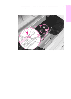
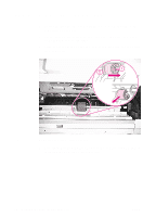
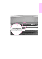
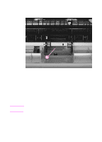
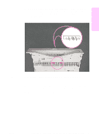
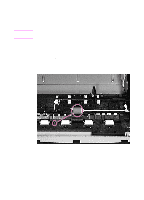
4 With the other hand inside the printer, remove the separation pad (Figure 8, item 1). Figure 8 Note Removing the Tray 1 separation pad (inside top of the printer) 5 With the silver clip facing the front of the printer, firmly press the new separation pad into the holder until it clicks into place. 6 Install the new Tray 1 pickup roller. a. Orient the roller so that the thumb grip (Figure 6, item 2) is on the left. b. Insert the roller onto the shaft, and then slide the roller to the right until it is seated. c. Slide the roller and cam to the left until it clicks into place. Make sure that the locking tab is engaged by trying to move the roller to the right. 14 Installing the printer maintenance kit ENWW
-
 1
1 -
2
-
3
-
4
-
5
-
6
-
7
-
8
-
9
-
10
-
 11
11 -
 12
12 -
 13
13 -
 14
14 -
 15
15 -
 16
16 -
 17
17 -
 18
18 -
 19
19 -
 20
20 -
 21
21 -
22
-
23
-
24
-
25
-
26
-
27
-
28
-
29
-
30
-
31
-
32
-
33
-
34
-
35
-
36
-
37
-
38
-
39
-
40
-
41
-
42
-
43
-
44
-
45
-
46
-
47
-
48
-
49
-
50
-
51
-
52
-
53
-
54
-
55
-
56
-
57
-
58
-
59
-
60
-
61
-
62
-
63
-
64
-
65
-
66
-
67
-
68
-
69
-
70
-
71
-
72
-
73
-
74
-
75
-
76
-
77
-
78
-
79
-
80
-
81
-
82
-
83
-
84
-
85
-
86
-
87
-
88
-
89
-
90
-
91
-
92
-
93
-
94
-
95
-
96
-
97
-
98
-
99
-
100
-
101
-
102
-
103
-
104
-
105
-
106
-
107
-
108
-
109
-
110
-
111
-
112
-
113
-
114
-
115
-
116
-
117
-
118
-
119
-
120
-
121
-
122
-
123
-
124
-
125
-
126
-
127
-
128
-
129
-
130
-
131
-
132
-
133
-
134
-
135
-
136
-
137
-
138
-
139
-
140
-
141
-
142
-
143
-
144
-
145
-
146
-
147
-
148
-
149
-
150
-
151
-
152
-
153
-
154
-
155
-
156
-
157
-
158
-
159
-
160
-
161
-
162
-
163
-
164
-
165
-
166
-
167
-
168
-
169
-
170
-
171
-
172
-
173
-
174
-
175
-
176
-
177
-
178
-
179
-
180
-
181
-
182
-
183
-
184
-
185
-
186
 |
 |

14
Installing the printer maintenance kit
ENWW
4
With the other hand inside the printer, remove the separation pad
(Figure 8, item 1).
Figure 8
Removing the Tray 1 separation pad (inside top of the printer)
5
With the silver clip facing the front of the printer, firmly press the
new separation pad into the holder until it clicks into place.
6
Install the new Tray 1 pickup roller.
a.
Orient the roller so that the thumb grip (Figure 6, item 2) is on
the left.
b.
Insert the roller onto the shaft, and then slide the roller to the
right until it is seated.
c.
Slide the roller and cam to the left until it clicks into place.
Note
Make sure that the locking tab is engaged by trying to move the roller
to the right.