HP 5100 HP LaserJet 5100 Series - Printer Maintenance Kit - Page 26
The fuser power connection is on the left side of the assembly. - fuser assembly
 |
UPC - 808736092500
View all HP 5100 manuals
Add to My Manuals
Save this manual to your list of manuals |
Page 26 highlights
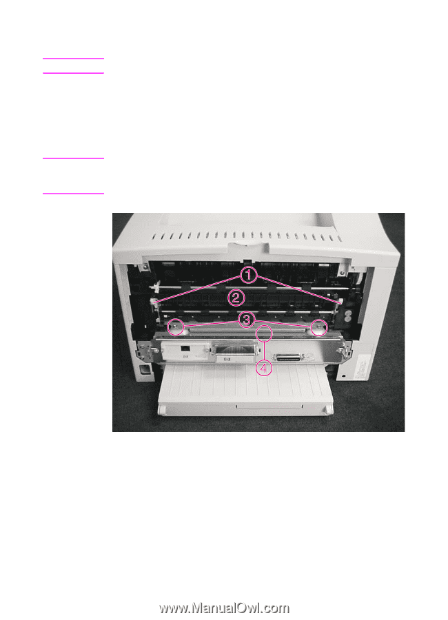
Hint Note 3 Slide the door to the left, and then remove it from the printer. For reassembly, insert the pin on the left side of the cover first. 4 Facing the back of the printer, remove the two machine screws (Figure 18, item 3) holding the fuser (item 2) in the chassis. 5 Using a small, flat-blade screw driver, lift at area 4 in Figure 18 to disengage the fuser assembly. Grasp the green handles (item 1) and strongly pull the fuser out of the chassis. The fuser power connection is on the left side of the assembly. To disengage and remove the fuser from the printer, pull strongly on the left side of the fuser. Figure 18 Removing the fuser (rear view of the printer) 24 Installing the printer maintenance kit ENWW
-
 1
1 -
2
-
3
-
4
-
5
-
6
-
7
-
8
-
9
-
10
-
11
-
12
-
13
-
14
-
15
-
16
-
17
-
18
-
19
-
20
-
 21
21 -
 22
22 -
 23
23 -
 24
24 -
 25
25 -
 26
26 -
 27
27 -
 28
28 -
 29
29 -
 30
30 -
 31
31 -
32
-
33
-
34
-
35
-
36
-
37
-
38
-
39
-
40
-
41
-
42
-
43
-
44
-
45
-
46
-
47
-
48
-
49
-
50
-
51
-
52
-
53
-
54
-
55
-
56
-
57
-
58
-
59
-
60
-
61
-
62
-
63
-
64
-
65
-
66
-
67
-
68
-
69
-
70
-
71
-
72
-
73
-
74
-
75
-
76
-
77
-
78
-
79
-
80
-
81
-
82
-
83
-
84
-
85
-
86
-
87
-
88
-
89
-
90
-
91
-
92
-
93
-
94
-
95
-
96
-
97
-
98
-
99
-
100
-
101
-
102
-
103
-
104
-
105
-
106
-
107
-
108
-
109
-
110
-
111
-
112
-
113
-
114
-
115
-
116
-
117
-
118
-
119
-
120
-
121
-
122
-
123
-
124
-
125
-
126
-
127
-
128
-
129
-
130
-
131
-
132
-
133
-
134
-
135
-
136
-
137
-
138
-
139
-
140
-
141
-
142
-
143
-
144
-
145
-
146
-
147
-
148
-
149
-
150
-
151
-
152
-
153
-
154
-
155
-
156
-
157
-
158
-
159
-
160
-
161
-
162
-
163
-
164
-
165
-
166
-
167
-
168
-
169
-
170
-
171
-
172
-
173
-
174
-
175
-
176
-
177
-
178
-
179
-
180
-
181
-
182
-
183
-
184
-
185
-
186
 |
 |
24
Installing the printer maintenance kit
ENWW
3
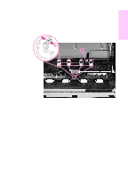
Slide the door to the left, and then remove it from the printer.
Hint
For reassembly, insert the pin on the left side of the cover first.
4
Facing the back of the printer, remove the two machine screws
(Figure 18, item 3) holding the fuser (item 2) in the chassis.
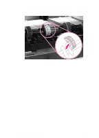
5
Using a small, flat-blade screw driver, lift at area 4 in Figure 18 to
disengage the fuser assembly. Grasp the green handles (item 1)
and strongly pull the fuser out of the chassis.
Note
The fuser power connection is on the left side of the assembly. To
disengage and remove the fuser from the printer, pull strongly on the
left side of the fuser.
Figure 18
Removing the fuser (rear view of the printer)