HP 6005 Hardware Reference Guide - HP Compaq 6005 Pro Microtower Model - Page 35
Installing an External 5.25-inch or 3.5-inch Drive, CAUTION,
 |
View all HP 6005 manuals
Add to My Manuals
Save this manual to your list of manuals |
Page 35 highlights
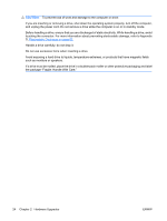
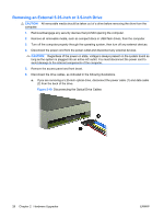
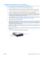
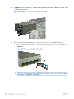
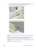
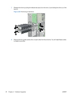
Installing an External 5.25-inch or 3.5-inch Drive NOTE: The system does not support Parallel ATA (PATA) optical drives. 1. Remove/disengage any security devices that prohibit opening the computer. 2. Remove all removable media, such as compact discs or USB flash drives, from the computer. 3. Turn off the computer properly through the operating system, then turn off any external devices. 4. Disconnect the power cord from the power outlet and disconnect any external devices. CAUTION: Regardless of the power-on state, voltage is always present on the system board as long as the system is plugged into an active AC outlet. You must disconnect the power cord to avoid damage to the internal components of the computer. 5. If you are installing a drive in a bay covered by a bezel blank, remove the front bezel then remove the bezel blank. See Removing Bezel Blanks on page 12 for more information. 6. Remove the access panel and front bezel. 7. Install four M3 metric guide screws in the lower holes on each side of the drive. HP has provided eight extra M3 metric guide screws on the front of the chassis, under the front bezel. The M3 metric guide screws are black. Refer to Installing and Removing Drives on page 23 for an illustration of the extra M3 metric guide screws location. CAUTION: Use only 5-mm long screws as guide screws. Longer screws can damage the internal components of the drive. NOTE: When replacing the drive, transfer the four M3 metric guide screws from the old drive to the new one. Figure 2-23 Installing Guide Screws (Optical Drive Shown) ENWW Installing and Removing Drives 29
-
 1
1 -
2
-
3
-
4
-
5
-
6
-
7
-
8
-
9
-
10
-
11
-
12
-
13
-
14
-
15
-
16
-
17
-
18
-
19
-
20
-
21
-
22
-
23
-
24
-
25
-
26
-
27
-
28
-
29
-
 30
30 -
 31
31 -
 32
32 -
 33
33 -
 34
34 -
 35
35 -
 36
36 -
 37
37 -
 38
38 -
 39
39 -
 40
40 -
41
-
42
-
43
-
44
-
45
-
46
-
47
-
48
-
49
-
50
-
51
-
52
-
53
-
54
-
55
-
56
-
57
-
58
-
59
-
60
-
61
-
62
 |
 |