HP 620 Compaq 320, 321, 420, 421, 620 and 621 Notebook PCs HP 420 and 620 Not - Page 104
System board, When replacing the system board
 |
UPC - 885631889732
View all HP 620 manuals
Add to My Manuals
Save this manual to your list of manuals |
Page 104 highlights
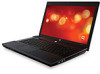
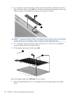
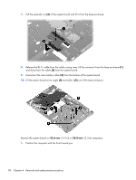
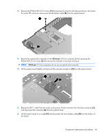
System board NOTE: The system board spare part kit includes replacement thermal material. Description System board with UMA graphics and RTC battery with GL40 chipset having 667-MHz FSB System board with UMA graphics and RTC battery with GM45 chipset having 1066-MHz FSB System board with discrete graphics and RTC battery with PM45 chipset having 1066-MHz FSB Spare part number 605748-001 605747-001 605746-001 Before removing the system board, follow these steps: 1. Shut down the computer. If you are unsure whether the computer is off or in Hibernation, turn the computer on, and then shut it down through the operating system. 2. Disconnect all external devices connected to the computer. 3. Disconnect the power from the computer by first unplugging the power cord from the AC outlet and then unplugging the AC adapter from the computer. 4. Remove the battery (see Battery on page 53). 5. Remove the service door (see Service door on page 53). 6. Remove the hard drive (see Hard drive on page 56). 7. Remove the optical drive (see Optical drive on page 62). 8. Remove the fan (see Fan on page 64). 9. Remove the palm rest (see Palm rest on page 68). 10. Remove the keyboard (see Keyboard on page 73). 11. Remove the top cover (see Top cover on page 77). When replacing the system board, be sure that the following components are removed from the defective system board and installed on the replacement system board: ● Memory module (see Memory module on page 59) ● WLAN module (see WLAN module on page 61) ● Modem module (see Modem module on page 103) ● Heat sink (see Heat sink on page 65) ● Processor (see Processor on page 66) ● Audio board (see Audio board on page 105) 96 Chapter 4 Removal and replacement procedures
-
 1
1 -
2
-
3
-
4
-
5
-
6
-
7
-
8
-
9
-
10
-
11
-
12
-
13
-
14
-
15
-
16
-
17
-
18
-
19
-
20
-
21
-
22
-
23
-
24
-
25
-
26
-
27
-
28
-
29
-
30
-
31
-
32
-
33
-
34
-
35
-
36
-
37
-
38
-
39
-
40
-
41
-
42
-
43
-
44
-
45
-
46
-
47
-
48
-
49
-
50
-
51
-
52
-
53
-
54
-
55
-
56
-
57
-
58
-
59
-
60
-
61
-
62
-
63
-
64
-
65
-
66
-
67
-
68
-
69
-
70
-
71
-
72
-
73
-
74
-
75
-
76
-
77
-
78
-
79
-
80
-
81
-
82
-
83
-
84
-
85
-
86
-
87
-
88
-
89
-
90
-
91
-
92
-
93
-
94
-
95
-
96
-
97
-
98
-
 99
99 -
 100
100 -
 101
101 -
 102
102 -
 103
103 -
 104
104 -
 105
105 -
 106
106 -
 107
107 -
 108
108 -
 109
109 -
110
-
111
-
112
-
113
-
114
-
115
-
116
-
117
-
118
-
119
-
120
-
121
-
122
-
123
-
124
-
125
-
126
-
127
-
128
-
129
-
130
-
131
-
132
-
133
-
134
-
135
-
136
-
137
-
138
-
139
-
140
-
141
-
142
-
143
-
144
-
145
-
146
-
147
-
148
-
149
-
150
-
151
-
152
-
153
-
154
-
155
-
156
-
157
-
158
-
159
-
160
-
161
-
162
-
163
-
164
-
165
 |
 |