HP 620 Compaq 320, 321, 420, 421, 620 and 621 Notebook PCs HP 420 and 620 Not - Page 107
Remove the Phillips PM2.0×3.0 screw, Phillips PM2.0×3.0 screw
 |
UPC - 885631889732
View all HP 620 manuals
Add to My Manuals
Save this manual to your list of manuals |
Page 107 highlights
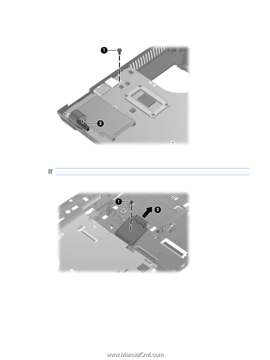
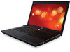
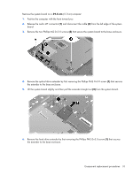
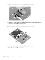
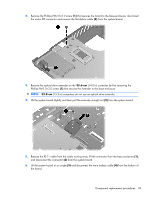
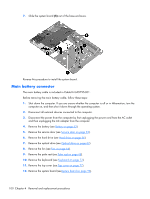
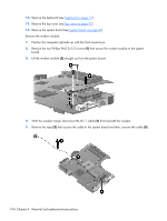
2. Remove the Phillips PM2.0×3.0 screw (1) that secures the board to the base enclosure, disconnect the audio ZIF connector and remove the flat-ribbon cable (2) from the system board. 3. Remove the optical drive extender on the 35.6-cm (14.0-in) computer by first removing the Phillips PM2.0×3.0 screw (1) that secures the extender to the base enclosure. NOTE: 33.8-cm (13.3-in) computers do not use an optical drive extender. 4. Lift the system board slightly and then pull the extender straight out (2) from the system board. 5. Release the RJ-11 cable from the cable routing area, lift the connector from the base enclosure (1), and disconnect the connector (2) from the system board. 6. Lift the system board at an angle (3) and disconnect the main battery cable (4) from the bottom of the board. Component replacement procedures 99
-
 1
1 -
2
-
3
-
4
-
5
-
6
-
7
-
8
-
9
-
10
-
11
-
12
-
13
-
14
-
15
-
16
-
17
-
18
-
19
-
20
-
21
-
22
-
23
-
24
-
25
-
26
-
27
-
28
-
29
-
30
-
31
-
32
-
33
-
34
-
35
-
36
-
37
-
38
-
39
-
40
-
41
-
42
-
43
-
44
-
45
-
46
-
47
-
48
-
49
-
50
-
51
-
52
-
53
-
54
-
55
-
56
-
57
-
58
-
59
-
60
-
61
-
62
-
63
-
64
-
65
-
66
-
67
-
68
-
69
-
70
-
71
-
72
-
73
-
74
-
75
-
76
-
77
-
78
-
79
-
80
-
81
-
82
-
83
-
84
-
85
-
86
-
87
-
88
-
89
-
90
-
91
-
92
-
93
-
94
-
95
-
96
-
97
-
98
-
99
-
100
-
101
-
 102
102 -
 103
103 -
 104
104 -
 105
105 -
 106
106 -
 107
107 -
 108
108 -
 109
109 -
 110
110 -
 111
111 -
 112
112 -
113
-
114
-
115
-
116
-
117
-
118
-
119
-
120
-
121
-
122
-
123
-
124
-
125
-
126
-
127
-
128
-
129
-
130
-
131
-
132
-
133
-
134
-
135
-
136
-
137
-
138
-
139
-
140
-
141
-
142
-
143
-
144
-
145
-
146
-
147
-
148
-
149
-
150
-
151
-
152
-
153
-
154
-
155
-
156
-
157
-
158
-
159
-
160
-
161
-
162
-
163
-
164
-
165
 |
 |