HP 620 Compaq 320, 321, 420, 421, 620 and 621 Notebook PCs HP 420 and 620 Not - Page 88
located in the battery bay, four Torx M2.5×6.0, Remove the two Phillips PM2.0×2.0 screws
 |
UPC - 885631889732
View all HP 620 manuals
Add to My Manuals
Save this manual to your list of manuals |
Page 88 highlights
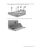
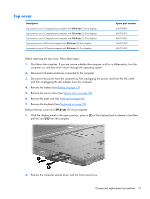
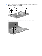
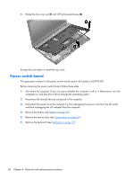
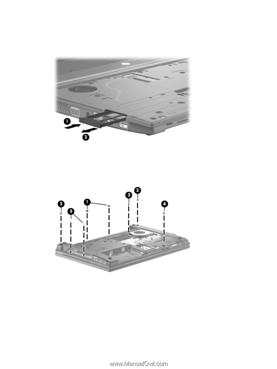
Remove the top cover on a 35.6-cm (14.0-in) and 33.8-cm (13.3-in) computer: 1. With the display panel in the open position, press in (1) of the ExpressCard to release it and then pull the card (2) from the computer. 2. Position the computer upside down with the front toward you. 3. Remove the two Phillips PM2.0×2.0 screws (1) located in the battery bay, four Torx M2.5×6.0 screws (2), (3), and (4), and the two Phillips PM2.0×3.0 screws (5) located in the recess near the optical drive. 80 Chapter 4 Removal and replacement procedures
-
 1
1 -
2
-
3
-
4
-
5
-
6
-
7
-
8
-
9
-
10
-
11
-
12
-
13
-
14
-
15
-
16
-
17
-
18
-
19
-
20
-
21
-
22
-
23
-
24
-
25
-
26
-
27
-
28
-
29
-
30
-
31
-
32
-
33
-
34
-
35
-
36
-
37
-
38
-
39
-
40
-
41
-
42
-
43
-
44
-
45
-
46
-
47
-
48
-
49
-
50
-
51
-
52
-
53
-
54
-
55
-
56
-
57
-
58
-
59
-
60
-
61
-
62
-
63
-
64
-
65
-
66
-
67
-
68
-
69
-
70
-
71
-
72
-
73
-
74
-
75
-
76
-
77
-
78
-
79
-
80
-
81
-
82
-
 83
83 -
 84
84 -
 85
85 -
 86
86 -
 87
87 -
 88
88 -
 89
89 -
 90
90 -
 91
91 -
 92
92 -
 93
93 -
94
-
95
-
96
-
97
-
98
-
99
-
100
-
101
-
102
-
103
-
104
-
105
-
106
-
107
-
108
-
109
-
110
-
111
-
112
-
113
-
114
-
115
-
116
-
117
-
118
-
119
-
120
-
121
-
122
-
123
-
124
-
125
-
126
-
127
-
128
-
129
-
130
-
131
-
132
-
133
-
134
-
135
-
136
-
137
-
138
-
139
-
140
-
141
-
142
-
143
-
144
-
145
-
146
-
147
-
148
-
149
-
150
-
151
-
152
-
153
-
154
-
155
-
156
-
157
-
158
-
159
-
160
-
161
-
162
-
163
-
164
-
165
 |
 |
Remove the top cover on a
35.6-cm
(14.0-in) and
33.8-cm
(13.3-in) computer:
1.
With the display panel in the open position, press in
(1)
of the ExpressCard to release it and then
pull the card
(2)
from the computer.
2.
Position the computer upside down with the front toward you.
3.
Remove the two Phillips PM2.0×2.0 screws
(1)
located in the battery bay, four Torx M2.5×6.0
screws
(2), (3)
, and
(4)
, and the two Phillips PM2.0×3.0 screws
(5)
located in the recess near
the optical drive.
80
Chapter 4
Removal and replacement procedures