HP 620 Compaq 320, 321, 420, 421, 620 and 621 Notebook PCs HP 420 and 620 Not - Page 97
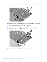
Remove eight Torx M2.5×6.0 screws, that secure the display to the base enclosure. Be careful
 |
UPC - 885631889732
View all HP 620 manuals
Add to My Manuals
Save this manual to your list of manuals |
Page 97 highlights
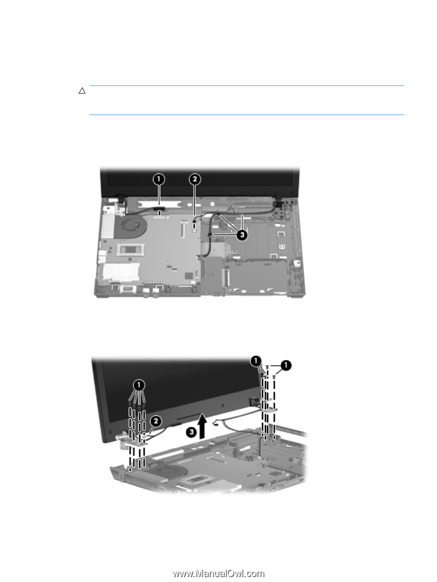
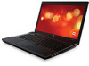
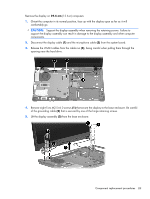
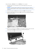
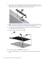
Remove the display on 39.6-cm (15.6-in) computers: 1. Orient the computer in its normal position, face up with the display open as far as it will comfortably go. CAUTION: Support the display assembly when removing the retaining screws. Failure to support the display assembly can result in damage to the display assembly and other computer components. 2. Disconnect the display cable (1) and the microphone cable (2) from the system board. 3. Release the WLAN cables from the cable run (3), being careful when pulling them through the opening near the hard drive. 4. Remove eight Torx M2.5×6.0 screws (1) that secure the display to the base enclosure. Be careful of the grounding cable (2) that is secured by one of the hinge retaining screws. 5. Lift the display assembly (3) from the base enclosure. Component replacement procedures 89
-
 1
1 -
2
-
3
-
4
-
5
-
6
-
7
-
8
-
9
-
10
-
11
-
12
-
13
-
14
-
15
-
16
-
17
-
18
-
19
-
20
-
21
-
22
-
23
-
24
-
25
-
26
-
27
-
28
-
29
-
30
-
31
-
32
-
33
-
34
-
35
-
36
-
37
-
38
-
39
-
40
-
41
-
42
-
43
-
44
-
45
-
46
-
47
-
48
-
49
-
50
-
51
-
52
-
53
-
54
-
55
-
56
-
57
-
58
-
59
-
60
-
61
-
62
-
63
-
64
-
65
-
66
-
67
-
68
-
69
-
70
-
71
-
72
-
73
-
74
-
75
-
76
-
77
-
78
-
79
-
80
-
81
-
82
-
83
-
84
-
85
-
86
-
87
-
88
-
89
-
90
-
91
-
 92
92 -
 93
93 -
 94
94 -
 95
95 -
 96
96 -
 97
97 -
 98
98 -
 99
99 -
 100
100 -
 101
101 -
 102
102 -
103
-
104
-
105
-
106
-
107
-
108
-
109
-
110
-
111
-
112
-
113
-
114
-
115
-
116
-
117
-
118
-
119
-
120
-
121
-
122
-
123
-
124
-
125
-
126
-
127
-
128
-
129
-
130
-
131
-
132
-
133
-
134
-
135
-
136
-
137
-
138
-
139
-
140
-
141
-
142
-
143
-
144
-
145
-
146
-
147
-
148
-
149
-
150
-
151
-
152
-
153
-
154
-
155
-
156
-
157
-
158
-
159
-
160
-
161
-
162
-
163
-
164
-
165
 |
 |