HP 8000f Maintenance and Service Guide: HP Compaq 8000f Elite Business PC Ultr - Page 72
Rear Fan,
 |
UPC - 885631750551
View all HP 8000f manuals
Add to My Manuals
Save this manual to your list of manuals |
Page 72 highlights
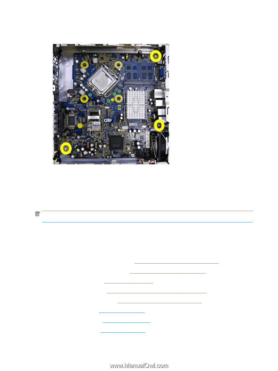
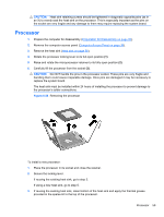
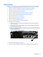
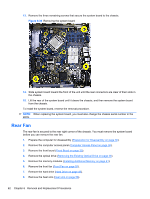
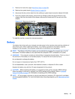
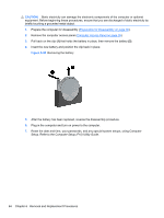
13. Remove the three remaining screws that secure the system board to the chassis. Figure 6-36 Removing the system board 14. Slide system board toward the front of the unit until the rear connectors are clear of their slots in the chassis. 15. Lift the rear of the system board until it clears the chassis, and then remove the system board from the chassis. To install the system board, reverse the removal procedure. NOTE: When replacing the system board, you must also change the chassis serial number in the BIOS. Rear Fan The rear fan is secured to the rear right corner of the chassis. You must remove the system board before you can remove the rear fan. 1. Prepare the computer for disassembly (Preparation for Disassembly on page 30). 2. Remove the computer access panel (Computer Access Panel on page 38). 3. Remove the front bezel (Front Bezel on page 39). 4. Remove the optical drive (Removing the Existing Optical Drive on page 46). 5. Remove the memory modules (Installing Additional Memory on page 41). 6. Remove the front fan (Front Fan on page 55). 7. Remove the hard drive (Hard Drive on page 49). 8. Remove the heat sink (Heat sink on page 58). 62 Chapter 6 Removal and Replacement Procedures
-
 1
1 -
2
-
3
-
4
-
5
-
6
-
7
-
8
-
9
-
10
-
11
-
12
-
13
-
14
-
15
-
16
-
17
-
18
-
19
-
20
-
21
-
22
-
23
-
24
-
25
-
26
-
27
-
28
-
29
-
30
-
31
-
32
-
33
-
34
-
35
-
36
-
37
-
38
-
39
-
40
-
41
-
42
-
43
-
44
-
45
-
46
-
47
-
48
-
49
-
50
-
51
-
52
-
53
-
54
-
55
-
56
-
57
-
58
-
59
-
60
-
61
-
62
-
63
-
64
-
65
-
66
-
 67
67 -
 68
68 -
 69
69 -
 70
70 -
 71
71 -
 72
72 -
 73
73 -
 74
74 -
 75
75 -
 76
76 -
 77
77 -
78
-
79
-
80
-
81
-
82
-
83
-
84
-
85
-
86
-
87
-
88
-
89
-
90
-
91
-
92
-
93
-
94
-
95
-
96
-
97
-
98
-
99
-
100
-
101
-
102
-
103
-
104
-
105
-
106
-
107
-
108
-
109
-
110
-
111
-
112
-
113
-
114
-
115
-
116
-
117
-
118
-
119
-
120
-
121
-
122
-
123
-
124
-
125
-
126
-
127
-
128
-
129
-
130
-
131
-
132
-
133
-
134
-
135
-
136
-
137
-
138
-
139
-
140
-
141
-
142
-
143
-
144
-
145
-
146
-
147
-
148
-
149
-
150
-
151
-
152
-
153
-
154
-
155
-
156
-
157
-
158
-
159
-
160
-
161
-
162
-
163
-
164
-
165
-
166
 |
 |