HP 9000 rp4440-8 Installation Guide, Sixth Edition - HP 9000 rp4410/rp4440
HP 9000 rp4440-8 Manual
 |
View all HP 9000 rp4440-8 manuals
Add to My Manuals
Save this manual to your list of manuals |
HP 9000 rp4440-8 manual content summary:
- HP 9000 rp4440-8 | Installation Guide, Sixth Edition - HP 9000 rp4410/rp4440 - Page 1
Installation Guide HP 9000 rp4410 and HP 9000 rp4440 Manufacturing Part Number: A9950-96010 Six Edition April 2007 Printed in the US - HP 9000 rp4440-8 | Installation Guide, Sixth Edition - HP 9000 rp4410/rp4440 - Page 2
to change without notice. The only warranties for HP products and services are set forth in the express warranty statements accompanying such products and services. Nothing herein should be construed as constituting an additional warranty. HP shall not be liable for technical or editorial errors - HP 9000 rp4440-8 | Installation Guide, Sixth Edition - HP 9000 rp4410/rp4440 - Page 3
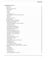
Server with a Lifter 21 Installing Additional Components 21 Required Service Tools 21 Accessing a Rack-Mounted Server 22 Accessing a Pedestal-Mounted Server Server Into a Rack, Non-HP rack, or Pedestal 72 HP Rack 72 Non-HP Rack 72 Pedestal Mount 72 Connecting the Cables 73 AC Input Power - HP 9000 rp4440-8 | Installation Guide, Sixth Edition - HP 9000 rp4410/rp4440 - Page 4
the Operating System 89 Supported Operating System 89 Booting and Shutting Down HP-UX 89 Verifying the Server Configuration Using Boot Console Handler 90 Troubleshooting 91 Troubleshooting Methodology 91 Troubleshooting Using the Server Power Button 91 Server Does Not Power On 92 BCH Menu - HP 9000 rp4440-8 | Installation Guide, Sixth Edition - HP 9000 rp4410/rp4440 - Page 5
76 Table 1-14. Console Connection Matrix 78 Table 1-15. LAN Configuration Methods 78 Table 1-16. ARP Ping Commands 80 Table 1-17. Power States 87 Table 1-18. Server Power Button Functions When Server is On and at BCH 92 Table 1-19. Server Power Button Functions When Server is On and OS - HP 9000 rp4440-8 | Installation Guide, Sixth Edition - HP 9000 rp4410/rp4440 - Page 6
Tables 6 - HP 9000 rp4440-8 | Installation Guide, Sixth Edition - HP 9000 rp4410/rp4440 - Page 7
HP 9000 rp4410 and rp4440 Servers (Top View 14 Figure 1-2. HP 9000 rp4410 and rp4440 Servers with Bezel Removed (Front View 15 Figure 1-3. HP 9000 rp4410 and rp4440 Servers (Rear View 15 Figure 1-4. Accessing T-25 Screws 22 Figure 1-5. Pedestal-Mounted Server . Hot-Swappable Power Supply Fan ( - HP 9000 rp4440-8 | Installation Guide, Sixth Edition - HP 9000 rp4410/rp4440 - Page 8
Figures Figure 1-44. Front Control Panel LEDs 95 Figure 1-45. QuickFind Diagnostic Label 98 8 - HP 9000 rp4440-8 | Installation Guide, Sixth Edition - HP 9000 rp4410/rp4440 - Page 9
About This Document This document describes how to unpack the HP 9000 rp4410 and HP 9000 rp4440 server, install additional components, start a server console session, power on the server, and boot the operating system. The document printing date and part number indicate the document's current - HP 9000 rp4440-8 | Installation Guide, Sixth Edition - HP 9000 rp4410/rp4440 - Page 10
A9950-96010 HP-UX 11i v1 HP-UX 11i v2 HP-UX 11i v3 A9950-96005 HP-UX 11i v1 N/A HP-UX 11i v1 Supported Product Versions Publication Date HP 9000 rp4410 and rp4440 April 2007 HP 9000 rp4410 and rp4440 HP 9000 rp4410 and rp4440 April 2005 July 2003 Document Organization This guide is - HP 9000 rp4440-8 | Installation Guide, Sixth Edition - HP 9000 rp4410/rp4440 - Page 11
one of the items. {} The contents are required in formats and command descriptions. If the contents HP-UX 11i operating system. Table 2 HP-UX 11i Releases Release Identifier B.11.20 B.11.22 B.11.23 B.11.31 Release Name HP-UX 11i v1.5 HP-UX 11i v1.6 HP-UX 11i v2.0 HP-UX 11i v3.0 Supported - HP 9000 rp4440-8 | Installation Guide, Sixth Edition - HP 9000 rp4410/rp4440 - Page 12
Related Documents You can find other information on HP server hardware management and diagnostic support tools in the following publications. Web Site for HP Technical Documentation: http://docs.hp.com Server Hardware Information: http://docs.hp.com/en/hw.html Diagnostics and Event Monitoring: - HP 9000 rp4440-8 | Installation Guide, Sixth Edition - HP 9000 rp4410/rp4440 - Page 13
"Connecting the Cables" on page 73 • "Console Setup" on page 75 • "Accessing the Host Console" on page 84 • "Powering ON and Powering OFF" on page 86 • "Booting the Operating System" on page 89 • "Troubleshooting" on page 91 Introduction The HP 9000 rp4410 and rp4440 servers are 1P/1C, 1P/2C, 2P/2C - HP 9000 rp4440-8 | Installation Guide, Sixth Edition - HP 9000 rp4410/rp4440 - Page 14
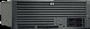
Installing the System Server Views Server Views Figure 1-1, Figure 1-2, and Figure 1-3 show the top, front, and rear views of the HP 9000 rp4410 and rp4440 servers. Figure 1-1 HP 9000 rp4410 and rp4440 Servers (Top View) 14 Chapter 1 - HP 9000 rp4440-8 | Installation Guide, Sixth Edition - HP 9000 rp4410/rp4440 - Page 15
View) Figure 1-3 HP 9000 rp4410 and rp4440 Servers (Rear View) Detailed Server Description The following sections list information on the main subsystems within the HP 9000 rp4410 and rp4440 servers. I/O Subsystem The following is supported on the HP 9000 rp4410 and rp4440 servers: • PCI-X slots - HP 9000 rp4440-8 | Installation Guide, Sixth Edition - HP 9000 rp4410/rp4440 - Page 16
cable. • Two USB 2.0 ports. • Three DB-9 ports (console, UPS, and modem). • Optional dual channel U320 RAID controller, two 68-pin external connectors (replaces SCSI interface). Processors The following is supported on the HP 9000 rp4410 and rp4440 servers: • 800 MHz/1.5 GB cache or 1 GHz/1.5 GB - HP 9000 rp4440-8 | Installation Guide, Sixth Edition - HP 9000 rp4410/rp4440 - Page 17
interleaved mode and chip spare. • Requires that DIMMs within each group of four (quad) be identical. Cooling Six cooling fans with N+1 redundancy. Power Supply Unit The following is supported on the HP 9000 rp4410 and rp4440 servers: • One 1200 W hot-swappable power supply. • Optional second 1200 - HP 9000 rp4440-8 | Installation Guide, Sixth Edition - HP 9000 rp4410/rp4440 - Page 18
these events helps you diagnose and troubleshoot problems with the server. Dimensions and Values Table 1-1 lists the dimensions and their values of the HP 9000 rp4410 and rp4440 servers. Table 1-1 Server Dimensions and Values Dimension Height Width Depth Weight Value 6.8 in (17.3 cm) 19 in - HP 9000 rp4440-8 | Installation Guide, Sixth Edition - HP 9000 rp4410/rp4440 - Page 19
components shipped with the server. 3 Install the server into a rack or pedestal mount. 4 Connect cables to the server. 4a Connect dc input power cable. 4b 4Connect LAN core I/O cable. 5 Set up the console. 6 Power on the server. 7 Access the console. 8 Boot the operating system - HP 9000 rp4440-8 | Installation Guide, Sixth Edition - HP 9000 rp4410/rp4440 - Page 20
to the server console. Step 3. Verify electrical requirements and ensure that grounding specifications and power requirements are met. Step 4. Validate server physical space requirements. Step 5. Confirm environmental requirements. Inspecting the Shipping Containers for Damage HP shipping containers - HP 9000 rp4440-8 | Installation Guide, Sixth Edition - HP 9000 rp4410/rp4440 - Page 21
Components This section describes how to install server components that are not installed before delivery. Required Service Tools Service of this product can require one or more of the following tools: • Electrically Conductive Field Service Kit (HP part number 9300-1155). • 1/4 inch flat blade - HP 9000 rp4440-8 | Installation Guide, Sixth Edition - HP 9000 rp4410/rp4440 - Page 22
Server The HP 9000 rp4410 and rp4440 servers are designed to be rack mounted. The following procedure explains how to gain access to a server the server to the rack. Step 2. Flip out the two pull handles at either end of the front bezel and slowly pull the unit forward by the handles. The server is - HP 9000 rp4440-8 | Installation Guide, Sixth Edition - HP 9000 rp4410/rp4440 - Page 23
1. Press the rail clips on either side of the server inward and push the server into the rack until it stops. Step 2. Replace the T-25 screws that fasten the server to the rack. Accessing a Pedestal-Mounted Server The HP 9000 rp4410 and rp4440 servers are also designed to be mounted in a pedestal - HP 9000 rp4440-8 | Installation Guide, Sixth Edition - HP 9000 rp4410/rp4440 - Page 24
Additional Components Front Panel Controls and Indicators The front panel of the server provides controls and indicators used for common operations. Figure 1-6, Figure 1-7, and Figure 1-8 show the front view of the server and the control panel. Figure 1-6 Front View with Bezel Control Panel - HP 9000 rp4440-8 | Installation Guide, Sixth Edition - HP 9000 rp4410/rp4440 - Page 25
LED System LED System LED Running Booting Attention Steady Flashing at 0.5 Hz Flashing at 1 Hz Green Green Yellow System LED System LED Power LED Power LED Power LED Disk LED Fault Off On On Off Thermal LED Thermal LED OK Warning Locator Button/LED Flashing at 2 Hz Off Steady Flashing - HP 9000 rp4440-8 | Installation Guide, Sixth Edition - HP 9000 rp4410/rp4440 - Page 26
, but less than five seconds-do not use. This initiates e-buzzer functions that are not supported in the HP 9000 rp4410 and rp4440 servers. • More than five seconds then released causes an immediate hard power off. NMI Button Use a paper clip to press this button. Press the non-maskable interrupt - HP 9000 rp4440-8 | Installation Guide, Sixth Edition - HP 9000 rp4410/rp4440 - Page 27
drive directly and turns on when a drive is accessed. Drive is operating. The drive status LED is green when power is applied to drive circuits. DVD, DVD-R, and DVD-RW Drives The server is delivered with one DVD drive (DVD-R and DVD-RW optional). Each of these devices has one activity LED - HP 9000 rp4440-8 | Installation Guide, Sixth Edition - HP 9000 rp4410/rp4440 - Page 28
Activity LED Emergency Eject Table 1-6 LED Activity LED DVD Drive LED Definitions State Flashing green Drive is active Description Front Bezel The server does not need to be powered off to remove the front bezel. Removing the Front Bezel To remove the front bezel, grasp the front bezel at the - HP 9000 rp4440-8 | Installation Guide, Sixth Edition - HP 9000 rp4410/rp4440 - Page 29
the top cover is replaced at the end of the operation, the chassis fans return to normal speed. Removing the Front Cover CAUTION Power the server off prior to removing the front cover. All components accessible behind the front cover are cold-swappable and require power to be off. To remove the - HP 9000 rp4440-8 | Installation Guide, Sixth Edition - HP 9000 rp4410/rp4440 - Page 30
Components Figure 1-12 Removing and Replacing the Front Cover Thumbscrews Step 4. Raise the cover slightly, and pull the cover toward the front of the server to free the tabs from the slots in the center of the chassis. Replacing the Front Cover To replace the front cover, follow these steps - HP 9000 rp4440-8 | Installation Guide, Sixth Edition - HP 9000 rp4410/rp4440 - Page 31
Figure 1-13 Installing the System Installing Additional Components Removing and Replacing the Top Cover Thumbscrews Rear of Chassis Replacing the Top Cover To replace the top cover, follow these steps: Step 1. Align the tabs at the rear of the top cover with the corresponding slots in the chassis - HP 9000 rp4440-8 | Installation Guide, Sixth Edition - HP 9000 rp4410/rp4440 - Page 32
Hot-Swappable Chassis Fan Units There are three hot-swappable chassis fan units in the server. • Fan units 0, 1, and 2 are in the center of the chassis, fits into the right-most position behind the power supply. Fan unit 2 cannot be installed in the left or center positions. 32 Chapter 1 - HP 9000 rp4440-8 | Installation Guide, Sixth Edition - HP 9000 rp4410/rp4440 - Page 33
to follow ESD safety precautions can result in damage to the server. NOTE A hot-swappable device does not require interaction with the operating system before the device is removed from or installed into the server. The ac power to the server does not need to be off to remove or replace a hot - HP 9000 rp4440-8 | Installation Guide, Sixth Edition - HP 9000 rp4410/rp4440 - Page 34
two minutes a soft-shutdown of the server occurs. Replacing a Hot-Swappable Fan Unit To replace a hot-swappable I/O or power supply fan unit, follow these steps: For assistance with this procedure, contact your local HP Authorized Service Provider. Observe all ESD safety precautions before attempting - HP 9000 rp4440-8 | Installation Guide, Sixth Edition - HP 9000 rp4410/rp4440 - Page 35
follow these steps: Step 1. If rack-mounted, slide the server out from the rack until it stops. (See "Extend the Server from the Rack" on page 22.) Step 2. Remove the lever attached to the side of the power supply cage to unplug the I/O baseboard assembly from the socket on the midplane riser board. - HP 9000 rp4440-8 | Installation Guide, Sixth Edition - HP 9000 rp4410/rp4440 - Page 36
assembly all the way to the rear until removed from chassis. CAUTION The I/O baseboard assembly is large. Be careful when lifting it out of the server chassis. 36 Chapter 1 - HP 9000 rp4440-8 | Installation Guide, Sixth Edition - HP 9000 rp4410/rp4440 - Page 37
are reinstalling the assembly that was previously removed from a configured server. To replace the I/O baseboard assembly, follow these steps: The I/O baseboard assembly is large. Use care when sliding it into the server chassis. Step 3. With the I/O baseboard flush against the midplane riser board - HP 9000 rp4440-8 | Installation Guide, Sixth Edition - HP 9000 rp4410/rp4440 - Page 38
Notice This product contains a Lithium battery (HP part number 1420-0386). WARNING Lithium according to the manufacturer's instructions. Replacing the System Battery Step 1. If rack-mounted, slide the server out from the rack until it stops. (See "Extend the Server from the Rack" on page 22.) - HP 9000 rp4440-8 | Installation Guide, Sixth Edition - HP 9000 rp4410/rp4440 - Page 39
Installing the System Installing Additional Components Figure 1-18 System Battery Location on I/O Baseboard Battery Step 5. Lift up the battery holder retaining clip with a flat-head screwdriver and push on the back of the battery to remove the battery from its socket. Step 6. Lift up the battery - HP 9000 rp4440-8 | Installation Guide, Sixth Edition - HP 9000 rp4410/rp4440 - Page 40
off to install a hot-swappable power supply. Installing Hot-Swappable Power Supplies This section provides instructions on how to install power supplies. Power Supply Load Order The supported configuration of an HP 9000 rp4410 or rp4440 server requires a minimum of one power supply. You can install - HP 9000 rp4440-8 | Installation Guide, Sixth Edition - HP 9000 rp4410/rp4440 - Page 41
system. Failure to observe this caution results in damage to the server. To install a hot-swappable power supply, follow these steps: Step 1. If rack-mounted, slide the server out from the rack until it stops. (See "Extend the Server from the Rack" on page 22.) Step 2. Remove the cable management - HP 9000 rp4440-8 | Installation Guide, Sixth Edition - HP 9000 rp4410/rp4440 - Page 42
Components Installing Hot-Pluggable Disk Drives One additional hot-pluggable disk drive can be added to the server in slot 2. Always use low profile disk drives (1 inch height) in the server. To install a hot-pluggable disk drive, follow these steps: Step 1. Remove the volume filler from slot - HP 9000 rp4440-8 | Installation Guide, Sixth Edition - HP 9000 rp4410/rp4440 - Page 43
1 and 2 Slot 2-SCSI ID 1 Slot 1-SCSI ID 0 Installing Processors This section provides information about installing processors. WARNING Voltages are present at various locations within the server whenever an ac power source is connected. This voltage is present even when the main - HP 9000 rp4440-8 | Installation Guide, Sixth Edition - HP 9000 rp4410/rp4440 - Page 44
RISC/Itanium dipswitch is set to PA-RISC for the HP 9000 rp4410 and rp4440 servers. If this switch is incorrectly set, the system does not enter into self test. Required Tools To install processors in the server, use the CPU Install Kit (HP part number 5069-5441). This kit consists of the following - HP 9000 rp4440-8 | Installation Guide, Sixth Edition - HP 9000 rp4410/rp4440 - Page 45
or rp4440 rp4440 only rp4440 only Dual Processor Module 1 2 3 4 Connector CPU0 CPU1 CPU2 CPU3 Removing the Processor Extender Board Installing the System Installing Additional Components WARNING Ensure that the system is powered off and all power sources have been disconnected from the server - HP 9000 rp4440-8 | Installation Guide, Sixth Edition - HP 9000 rp4410/rp4440 - Page 46
Installing the System Installing Additional Components Figure 1-23 Extender Board Latches Step 5. Pull out on the extraction levers to unplug the processor extender board from the socket located on the midplane riser board. Step 6. Pull out the processor extender board from the chassis. 46 - HP 9000 rp4440-8 | Installation Guide, Sixth Edition - HP 9000 rp4410/rp4440 - Page 47
attempting this procedure. Failure to follow ESD safety precautions can result in damage to the server. NOTE Before installing a processor into the server, read the following instructions carefully for a complete understanding of this process. To install a processor on the extender board, follow - HP 9000 rp4440-8 | Installation Guide, Sixth Edition - HP 9000 rp4410/rp4440 - Page 48
cable is not pinched between the heatsink and sheet metal frame of the extender board. Also, ensure that the two power cable ends attached to the dual processor module do not come unplugged from their sockets when you move the cable into place under the heatsink. See Figure 1- - HP 9000 rp4440-8 | Installation Guide, Sixth Edition - HP 9000 rp4410/rp4440 - Page 49
Figure 1-26 Processor Cable Placed Incorrectly Installing the System Installing Additional Components Heatsink Cable Placed Incorrectly Pinched Between Heatsink and Extender Board Frame Protective Plastic Sleeve Sheet Metal Frame Step 6. Lock the assembly to the socket by rotating the cam on the - HP 9000 rp4440-8 | Installation Guide, Sixth Edition - HP 9000 rp4410/rp4440 - Page 50
Torx-T15 Use Torx T15 Driver to Tighten Shoulder Screws and Thumbscrews 2.5 MM Allen Key Align Pins on Heatsink with Slots in Frame Slots* Slots* Power Cable Protected by Plastic Sleeve *Slots shown are at CPU1 socket. Processor shown is being mounted on socket CPU0 per load order. 50 Chapter 1 - HP 9000 rp4440-8 | Installation Guide, Sixth Edition - HP 9000 rp4410/rp4440 - Page 51
operation. • Use MAKODIAG provided by the offline diagnostic environment to exercise the processor. Installing Memory The standard configuration of HP 9000 rp4410 and rp4440 servers include a 16-DIMM memory extender board. This extender board must contain a minimum of 1 GB of memory (four 256 MB - HP 9000 rp4440-8 | Installation Guide, Sixth Edition - HP 9000 rp4410/rp4440 - Page 52
in quads 0, 1, and 2 Two fillers in quads 2 and 3 Two fillers total: Two fillers in quad 3 16 DIMMs in quads 0, 1, 2, and 3 No fillers required a. One DIMM filler board covers two adjacent DIMM connectors. Figure 1-28 16-DIMM Memory Extender Board Minimum Configuration DIMM Filler Table - HP 9000 rp4440-8 | Installation Guide, Sixth Edition - HP 9000 rp4410/rp4440 - Page 53
7 (quad 6 remains unfilled) 24 DIMMs in quads 0, 1, 2, 3, 4, and 5 No fillers required 28 DIMMs in quads 0, 1, 2, 3, 4, 5, and 6 No fillers required 32 DIMMs in quads 0, 1, 2, 3, 4, 5, 6, and 7 No fillers required a. One DIMM filler board covers two adjacent DIMM connectors. Chapter 1 53 - HP 9000 rp4440-8 | Installation Guide, Sixth Edition - HP 9000 rp4410/rp4440 - Page 54
Installing the System Installing Additional Components Figure 1-29 32-DIMM Memory Extender Board Minimum Configuration DIMM Filler 54 Chapter 1 - HP 9000 rp4440-8 | Installation Guide, Sixth Edition - HP 9000 rp4410/rp4440 - Page 55
boards is located under the front cover. Installing the System Installing Additional Components WARNING Ensure that the system is powered off and all power sources have been disconnected from the server prior to attempting this procedure. Voltages are present at various locations within the - HP 9000 rp4440-8 | Installation Guide, Sixth Edition - HP 9000 rp4410/rp4440 - Page 56
the tab in the connector.) Step 2. Firmly and evenly push on each end of the DIMM until it seats in the socket. Ensure that the extraction . Step 2. Align the memory extender board with the left and right chassis guide slots. Step 3. Slide the memory extender board in until it begins to seat - HP 9000 rp4440-8 | Installation Guide, Sixth Edition - HP 9000 rp4410/rp4440 - Page 57
/PCI-X The HP 9000 rp4410 and rp4440 servers support PCI/PCI-X hot-pluggable technology and includes six hot-pluggable PCI/PCI-X slots. Hot-Pluggable PCI/PCI-X Operations PCI/PCI-X hot-pluggable technology enables the following operations. For procedures with step-by-step instructions describing how - HP 9000 rp4440-8 | Installation Guide, Sixth Edition - HP 9000 rp4410/rp4440 - Page 58
Configurations PCI/PCI-X slots are numbered from 1 through 8 in the server as shown in Figure 1-32. Figure 1-32 Slot ID Numbering PCI LEDs Green Power LEDs Core I/O PCI-X Public I/O Hot-pluggable PCI-X Amber Attention LEDs The following describes configuration requirements for slots - HP 9000 rp4440-8 | Installation Guide, Sixth Edition - HP 9000 rp4410/rp4440 - Page 59
accepted and runs at the frequency shown. c. Incompatible frequency: card does not work. d. Incompatible bus: Card does not work. The new card does not initialize powers off. e. Maximum bus mode and frequency supported on shared slots is PCI-X 66 MHz. Chapter 1 59 - HP 9000 rp4440-8 | Installation Guide, Sixth Edition - HP 9000 rp4410/rp4440 - Page 60
and pull up on the MRL located on the OLX divider approximately 75 degrees. (Figure 1-33) CAUTION Do not pull up on the MRL of a powered on, occupied slot or the server will crash. For instructions on how to power off an occupied slot, see "OLR" on page 64. 60 Chapter 1 - HP 9000 rp4440-8 | Installation Guide, Sixth Edition - HP 9000 rp4410/rp4440 - Page 61
/PCI-X OLX Divider Layout PCI-X Card Latch Closed Position MRL-Closed Installing the System Installing Additional Components PCI-X Card Latch Open Position MRL-Open Power LED Light Pipe Attention Button Attention LED Light Pipe Step 4. Ensure that the MRL and the card latch on the OLX divider are - HP 9000 rp4440-8 | Installation Guide, Sixth Edition - HP 9000 rp4410/rp4440 - Page 62
Installing the System Installing Additional Components Figure 1-34 Inserting PCI/PCI-X Card Step 5. If the PCI/PCI-X card is full size, open the slider gate latch to access the card slot. 62 Chapter 1 - HP 9000 rp4440-8 | Installation Guide, Sixth Edition - HP 9000 rp4410/rp4440 - Page 63
Figure 1-35 Slider Gate Latch Installing the System Installing Additional Components Step 6. If the PCI/PCI-X card is full size, close the slider gate latch to secure the end of the card. (Figure 1-35) Step 7. Push the MRL down until it seats against the chassis wall. Chapter 1 63 - HP 9000 rp4440-8 | Installation Guide, Sixth Edition - HP 9000 rp4410/rp4440 - Page 64
server all the way back into the rack until it stops. OLR CAUTION For HP service bay. Step 4. Press the Attention button located on the OLX divider that controls the affected slot. The power LED starts to blink. Wait until the power the end of server models. You must remove the PCI/PCI-X card manually - HP 9000 rp4440-8 | Installation Guide, Sixth Edition - HP 9000 rp4410/rp4440 - Page 65
size, close the slider gate latch to secure the end of the card. (Figure 1-33) Step 12. Push server all the way back into the rack until it stops. Understanding LEDs and Hardware Errors Table 1-12 describes the hot-pluggable LED error conditions. Table 1-12 Hot-Pluggable LED Descriptions Power - HP 9000 rp4440-8 | Installation Guide, Sixth Edition - HP 9000 rp4410/rp4440 - Page 66
Components Troubleshooting PCI/PCI power off during a hot-plug removal operation, do not open the MRL on the OLX divider. This action causes system failure or operating system crashes. Converting SCSI From Simplex to Duplex This section explains how to convert the HP 9000 rp4410 or rp4440 server - HP 9000 rp4440-8 | Installation Guide, Sixth Edition - HP 9000 rp4410/rp4440 - Page 67
Ensure that the system is powered off and all power sources have been disconnected from the server prior to attempting this procedure. controller. Accessing the SCSI Backplane Before adding the accessories required to convert the server from simplex to duplex, you must remove outer components to - HP 9000 rp4440-8 | Installation Guide, Sixth Edition - HP 9000 rp4410/rp4440 - Page 68
0 and slot 1 are driven by SCSI channel A. When the duplex board is installed, the slot 1 hard disk drive is now driven by SCSI channel B. If HP-UX was previously installed and whole disk vxfs was not used, the system no longer boots. 68 Chapter 1 - HP 9000 rp4440-8 | Installation Guide, Sixth Edition - HP 9000 rp4410/rp4440 - Page 69
Figure 1-37 Installing the Duplex Board Installing the System Installing Additional Components Step 3. Secure the duplex board to the disk drive cage by the bracket and to the SCSI backplane by the SCSI connector sockets. (Figure 1-37) Step 4. Install the SCSI Cable B on the SCSI backplane. ( - HP 9000 rp4440-8 | Installation Guide, Sixth Edition - HP 9000 rp4410/rp4440 - Page 70
Installing the System Installing Additional Components Figure 1-38 Installing SCSI Cable B to the SCSI Backplane Step 5. Connect the other end of the SCSI Cable B to the SCSI B channel connector on the SCSI adapter board. (Figure 1-39) a. Release the SCSI Cable B from its stowed position within - HP 9000 rp4440-8 | Installation Guide, Sixth Edition - HP 9000 rp4410/rp4440 - Page 71
SCSI Adapter Board Replacing the Removed Modules To return the server to operational configuration, follow these steps: Step 1. Replace 6. If rack-mounted, slide the server back into the rack until it stops. (See "Installing the Server Into a Rack, Non-HP rack, or Pedestal" on page 72.) Chapter 1 - HP 9000 rp4440-8 | Installation Guide, Sixth Edition - HP 9000 rp4410/rp4440 - Page 72
you need an HP 9000 rp4440 Server Rackless Mount Kit. This kit comes with an installation guide titled Converting Your Rack Server to a Rackless Mount (HP part number A6979-96001). To convert a rack-mount server to a pedestal-mount server, see Converting Your Rack Server to a Pedestal Server on the - HP 9000 rp4440-8 | Installation Guide, Sixth Edition - HP 9000 rp4410/rp4440 - Page 73
power the server and to provide LAN connectivity for the server. AC Input Power The HP 9000 rp4410 and rp4440 servers come with one or two power supplies installed. A power . The server is shipped in simplex configuration which supports external devices. If you convert the server to duplex - HP 9000 rp4440-8 | Installation Guide, Sixth Edition - HP 9000 rp4410/rp4440 - Page 74
supply in slot P2. Plug the other end of the power cord into an appropriate outlet. Connecting to the LAN The server has the following ports that provide network connectivity: • iLO MP LAN port. Use this port to access the Integrity iLO MP through the LAN. • Console/Remote/UPS port (RS-232). Use - HP 9000 rp4440-8 | Installation Guide, Sixth Edition - HP 9000 rp4410/rp4440 - Page 75
cable from an available LAN port into a live connection on the network. Console Setup This section describes how to set up and start a console session on the server. Setting Up the Console Setting up the console includes the following steps: • Determine the physical access method to connect cables - HP 9000 rp4440-8 | Installation Guide, Sixth Edition - HP 9000 rp4410/rp4440 - Page 76
Installing the System Console Setup Setup Checklist Use the checklist in Table 1-13 to assist • RS-232 serial port 3 Log on to the iLO MP Log in to the iLO MP from a supported Web browser or command line using the default user name and password. 4 Change default user name and password Change - HP 9000 rp4440-8 | Installation Guide, Sixth Edition - HP 9000 rp4410/rp4440 - Page 77
Setup Flowchart Use this flowchart as a guide to assist in the Integrity iLO MP setup process. Figure 1-41 iLO MP Setup Flowchart Installing the System Console Setup , andanIPd IaPddardedsrsess Chapter 1 77 - HP 9000 rp4440-8 | Installation Guide, Sixth Edition - HP 9000 rp4410/rp4440 - Page 78
14 Console Connection Matrix Operating System Console Connection Method HP-UX LAN port Local RS-232 serial port Remote/modem port Required whether DHCP is enabled or disabled on the server, and if DHCP and DNS services are available to the server. (See Table 1-15 for possible scenarios.) - HP 9000 rp4440-8 | Installation Guide, Sixth Edition - HP 9000 rp4410/rp4440 - Page 79
Console servers with IP addresses, subnet masks, and gateway addresses. All HP 9000 entry class servers with iLO MP are shipped from the factory with DHCP enabled. TIP HP Connect the LAN cable from the server to an active network port. Step 3. Apply ac power to the server (if not already done). Step - HP 9000 rp4440-8 | Installation Guide, Sixth Edition - HP 9000 rp4410/rp4440 - Page 80
Installing the System Console Setup ARP Ping operational issues include the following: • You can use ARP Ping regardless of the status of DHCP, unless an IP address has ever been acquired using DHCP. • When ARP Ping is successful, DHCP status is disabled. • Some DHCP server options can cause the - HP 9000 rp4440-8 | Installation Guide, Sixth Edition - HP 9000 rp4410/rp4440 - Page 81
the server. The software emulates console output as it would appear on an ASCII terminal screen and displays it on a console device receive) • None (transmit) b. Verify that the terminal type is configured appropriately. Supported terminal types are as follows: • hpterm • vt100 • vt100+ • vt-utf8 - HP 9000 rp4440-8 | Installation Guide, Sixth Edition - HP 9000 rp4410/rp4440 - Page 82
emulation software application for instructions on how to configure the software options. Step 3. Use Table 1-14 to determine the required connection components and the ports used to connect the server to the console device. Step 4. Connect the cables. a. Connect the DB-9 end of the RS-232 serial - HP 9000 rp4440-8 | Installation Guide, Sixth Edition - HP 9000 rp4410/rp4440 - Page 83
Rights (Administrator) level user: login = Admin password = Admin • Console Rights (Operator) level user: login = Oper password = Oper NOTE account and password are case sensitive. IMPORTANT For security reasons, HP strongly recommends that you modify the default settings during the initial - HP 9000 rp4440-8 | Installation Guide, Sixth Edition - HP 9000 rp4410/rp4440 - Page 84
If you plan to use directory services, HP recommends leaving at least one local account enabled as an alternate method of access. Accessing the Host Console This section describes the different ways to access the host console of the server. Accessing the Host Console With the TUI - CO Command This - HP 9000 rp4440-8 | Installation Guide, Sixth Edition - HP 9000 rp4410/rp4440 - Page 85
Installing the System Accessing the Host Console Interacting with the iLO MP Using the Web GUI Web browser access is an embedded feature of the iLO MP. The iLO MP has a separate LAN port from the system LAN port. It requires a separate LAN drop, IP address, and networking information from that of - HP 9000 rp4440-8 | Installation Guide, Sixth Edition - HP 9000 rp4410/rp4440 - Page 86
key (?) at the top right corner of each page to display help about that page. Powering ON and Powering OFF This section provides information and procedures for powering on and powering off the server. Power States The server has three power states: • Standby power • Full power • Off 86 Chapter 1 - HP 9000 rp4440-8 | Installation Guide, Sixth Edition - HP 9000 rp4410/rp4440 - Page 87
feature is set to Always On through the iLO MP PR command, the server automatically powers on to the full power state when the power cord is plugged in to the server. To manually power on the server, follow these steps: Step 1. Plug all power cables into the receptacles on the rear panel of the - HP 9000 rp4440-8 | Installation Guide, Sixth Edition - HP 9000 rp4410/rp4440 - Page 88
from the receptacles on the rear panel of the server. Powering Off the Server Manually To manually power off the server, follow these steps: Step 1. Gracefully shut down the operating system. Step 2. Press the power button to power off the server. CAUTION The main dc voltage is now removed from - HP 9000 rp4440-8 | Installation Guide, Sixth Edition - HP 9000 rp4410/rp4440 - Page 89
servers is HP-UX 11i Version 1 (and higher HP-UX versions that support PA-RISC systems.) Booting and Shutting Down HP-UX This section describes booting and shutting down HP-UX on the HP 9000 rp4410 and rp4440 servers. • To boot HP-UX, follow these steps: - "Standard HP-UX Booting Using Boot Console - HP 9000 rp4440-8 | Installation Guide, Sixth Edition - HP 9000 rp4410/rp4440 - Page 90
the shutdown -h command. To reboot a halted server you must power on the server using the PC command at the iLO MP Command menu. • To shut down HP-UX and reboot the server, issue the shutdown -r command. Verifying the Server Configuration Using Boot Console Handler From the BCH Main Menu, enter in - HP 9000 rp4440-8 | Installation Guide, Sixth Edition - HP 9000 rp4410/rp4440 - Page 91
Boot Console Handler (BCH). Descriptions and user information about offline troubleshooting tools are available on the Web at: http://www.docs.hp.com. The offline tools are available for downloading at: http://www.software.hp.com. Troubleshooting Using the Server Power Button The server power button - HP 9000 rp4440-8 | Installation Guide, Sixth Edition - HP 9000 rp4410/rp4440 - Page 92
button is pressed. You must be aware of its uses to properly troubleshoot the system. NOTE If the server is off, and power is not connected to server power supplies, pressing the power button has no effect. Power problems during installation are usually related to the installation process. If the - HP 9000 rp4440-8 | Installation Guide, Sixth Edition - HP 9000 rp4410/rp4440 - Page 93
the System Troubleshooting • If the console shows that the server is powered on, but server LEDs indicate that power is off, remove and reseat connectors on the LED status board. If the problem persists, replace the LED status board. If the console shows that the server is not powered on (server is - HP 9000 rp4440-8 | Installation Guide, Sixth Edition - HP 9000 rp4410/rp4440 - Page 94
interconnections. If you are experiencing monitor, keyboard, or mouse problems, follow these steps: 1. Check the monitor controls. Adjust contrast and brightness as required. 2. Inspect all power and interconnecting cables. Check that all console connectors are fully engaged. 3. Check that all iLO - HP 9000 rp4440-8 | Installation Guide, Sixth Edition - HP 9000 rp4410/rp4440 - Page 95
server console session. Step 2. Insert the CD with the copy of the latest version of the firmware. Step 3. Using the BCH menu prompt, boot to the drive that contains the CD with the updated firmware. Step 4. Follow the instructions to update the firmware. Troubleshooting LEDs Power LED Power Button - HP 9000 rp4440-8 | Installation Guide, Sixth Edition - HP 9000 rp4410/rp4440 - Page 96
Troubleshooting Table 1-21 Front Control Panel LED Definitions (Continued) LED/ Button System LED State Flash Rate Color Attention Flashing at 1 Hz Yellow System LED System LED Power LED Power LED Power and is attached to the top of the power supply cage. This panel contains LEDs that - HP 9000 rp4440-8 | Installation Guide, Sixth Edition - HP 9000 rp4410/rp4440 - Page 97
. The processors are mismatched-review the information on installing processors. A required component(s) is not detected. Check that recently installed items are correctly installed. Make sure nothing is blocking server airflow. Check that recently installed items are correctly installed. An event - HP 9000 rp4440-8 | Installation Guide, Sixth Edition - HP 9000 rp4410/rp4440 - Page 98
Installing the System Troubleshooting Figure 1-45 QuickFind Diagnostic Label Processor Subsystem I/O VRM CPU VRM Fan Memory 0 Memory 1 Memory 2 Memory 3 Memory 4 Memory 5 Memory 6 Memory 7 Power Supply Memory Config Error Processor Config Error Missing Component System Temperature Check Event Log - HP 9000 rp4440-8 | Installation Guide, Sixth Edition - HP 9000 rp4410/rp4440 - Page 99
to solve the problem. • Note failure symptoms and error indications (LEDs and messages) by checking the system event log. • Try to determine precisely what did or did not happen. Step 2. Collect the following information: • The model number of your server (for example, HP 9000 rp4440) • The product - HP 9000 rp4440-8 | Installation Guide, Sixth Edition - HP 9000 rp4410/rp4440 - Page 100
Installing the System Troubleshooting 100 Chapter 1 - HP 9000 rp4440-8 | Installation Guide, Sixth Edition - HP 9000 rp4410/rp4440 - Page 101
(BCH), 89 C cables, to connect power and LAN, 73 CM command, 87, 88 command mode See CM, 87 connecting to the LAN, 74 console accessing host with GUI, 85 accessing host with TUI, 84 determining connection method, 78 problems, troubleshooting, 94 setup, 75 contacting HP, 99 controls CD/DVD controls - HP 9000 rp4440-8 | Installation Guide, Sixth Edition - HP 9000 rp4410/rp4440 - Page 102
troubleshooting, 66 pedestal accessing the server, 23 convert from rack mount, 72 ports server rear, 75 102 power button, 26, 91 full state, 86 off state, 86 PR command, 87 problems, 92 reset command See PR standby state, 86 states, 86 supplies, installing, 40 powering off the server, 88 manually - HP 9000 rp4440-8 | Installation Guide, Sixth Edition - HP 9000 rp4410/rp4440 - Page 103
troubleshooting methodology, 91 operating system, 93 U unloading the server, 21 unpacking, inspecting for damage, 20 user accounts modifying, 83 V validate server configuration, 90 verify site preparation, 20 W Web iLO MP login page, 85 iLO MP status summary page, 85 iLO MP, launch help, 86
-
 1
1 -
 2
2 -
 3
3 -
 4
4 -
 5
5 -
 6
6 -
 7
7 -
8
-
9
-
10
-
11
-
12
-
13
-
14
-
15
-
16
-
17
-
18
-
19
-
20
-
21
-
22
-
23
-
24
-
25
-
26
-
27
-
28
-
29
-
30
-
31
-
32
-
33
-
34
-
35
-
36
-
37
-
38
-
39
-
40
-
41
-
42
-
43
-
44
-
45
-
46
-
47
-
48
-
49
-
50
-
51
-
52
-
53
-
54
-
55
-
56
-
57
-
58
-
59
-
60
-
61
-
62
-
63
-
64
-
65
-
66
-
67
-
68
-
69
-
70
-
71
-
72
-
73
-
74
-
75
-
76
-
77
-
78
-
79
-
80
-
81
-
82
-
83
-
84
-
85
-
86
-
87
-
88
-
89
-
90
-
91
-
92
-
93
-
94
-
95
-
96
-
97
-
98
-
99
-
100
-
101
-
102
-
103
 |
 |

Installation Guide
HP 9000 rp4410 and HP 9000 rp4440
Manufacturing Part Number: A9950-96010
Six Edition
April 2007
Printed in the US