HP A1310n Upgrading and Servicing Guide
HP A1310n - Pavilion - 1 GB RAM Manual
 |
View all HP A1310n manuals
Add to My Manuals
Save this manual to your list of manuals |
HP A1310n manual content summary:
- HP A1310n | Upgrading and Servicing Guide - Page 1
Upgrading and Servicing Guide - HP A1310n | Upgrading and Servicing Guide - Page 2
furnished by HP. This document contains proprietary information that is protected by copyright. All rights are reserved. No part of this for limited viewing uses only. Microsoft and Windows are U.S. Registered trademarks of Microsoft Corporation. HP supports lawful use of technology and does not - HP A1310n | Upgrading and Servicing Guide - Page 3
Replacing Drives 3 Removing a Drive 4 Replacing or Adding a Drive 5 Adding Memory 7 Removing a Memory Module 7 Installing a Memory Module 8 Removing or Installing an Add-In Card 8 Removing an Add-In Card 9 Installing an Add-In Card 9 Replacing the Battery 10 Upgrading and Servicing Guide - HP A1310n | Upgrading and Servicing Guide - Page 4
iv Upgrading and Servicing Guide - HP A1310n | Upgrading and Servicing Guide - Page 5
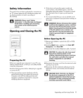
"Safety Information" in the Warranty and Support Guide before installing and connecting your system to the electrical power system. Opening and Closing the PC • to upgrade or service the PC. • These procedures assume familiarity with the general terminology associated with personal computers and - HP A1310n | Upgrading and Servicing Guide - Page 6
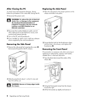
card (NIC) (labeled as an Ethernet connector). 2 Reconnect the modem/telephone cable, and all other cables (such as the keyboard, mouse, and monitor) and external devices. 3 Turn on the PC and all peripherals. 4 If you installed an add-in card, install any software drivers supplied by the card - HP A1310n | Upgrading and Servicing Guide - Page 7
(blank plate) or a CD-ROM, CD-RW, DVD-ROM, DVD+RW/+R, or combination drive C Memory card reader (select models) D Diskette (floppy) drive (select models) E Front connector panel (no replacement instructions) F Hard disk drive G Second hard disk drive (select models) Upgrading and Servicing Guide 3 - HP A1310n | Upgrading and Servicing Guide - Page 8
For a second hard disk drive, remove the two screws (3) and then slide the drive part way back out of the bay (4). Disconnecting the Optical Drive Cables Disconnecting the Memory Card Reader Drive Cable Removing the Second Hard Disk Drive 4 Upgrading and Servicing Guide Disconnecting the Diskette - HP A1310n | Upgrading and Servicing Guide - Page 9
new drive (two on each side). The screws help guide the drive into its proper position in the bay. For a second hard disk drive, skip this step and go to step 5. 5 Slide the drive part way into the drive bay, making sure to align the guide screws with the guide slots. Upgrading and Servicing Guide - HP A1310n | Upgrading and Servicing Guide - Page 10
to your drive as indicated in the following illustrations. If it is present, reconnect the sound cable. Connecting the Optical Drive Cables NOTE: An optical drive may include a sound cable. Connect this cable also. Connecting the Serial ATA Hard Disk Drive Cables 6 Upgrading and Servicing Guide - HP A1310n | Upgrading and Servicing Guide - Page 11
To determine which type and speed of memory module your PC uses, and for specific memory module information and specifications, go to the Web site listed in your Warranty and Support Guide and click the Support link. WARNING: Using the wrong type of memory module could damage the system. Removing - HP A1310n | Upgrading and Servicing Guide - Page 12
each board/card in the computer. The total +5 V current draw in a fully loaded system (one with all add-in card slots filled) must not exceed the total number of slots multiplied by 2 amps. A Phillips screwdriver is needed to remove, replace, or add an add-in card. 8 Upgrading and Servicing Guide - HP A1310n | Upgrading and Servicing Guide - Page 13
and close the PC. See "Opening and Closing the PC" on page 1. NOTE: If the new card or device isn't working, read through the card manufacturer's installation instructions, and recheck all connections, including those to the card, power supply, keyboard, and monitor. Upgrading and Servicing Guide 9 - HP A1310n | Upgrading and Servicing Guide - Page 14
CR2032 battery in the socket, with the positive (+) side facing the latch. 7 Replace memory modules or cables you removed. 8 Set the chassis upright. 9 Complete the procedures to replace the side panel, and to close the PC. See "Opening and Closing the PC" on page 1. 10 Upgrading and Servicing Guide - HP A1310n | Upgrading and Servicing Guide - Page 15
Upgrading and Servicing Guide 11 - HP A1310n | Upgrading and Servicing Guide - Page 16
Printed in
-
 1
1 -
 2
2 -
 3
3 -
 4
4 -
 5
5 -
 6
6 -
 7
7 -
8
-
9
-
10
-
11
-
12
-
13
-
14
-
15
-
16
 |
 |

Upgrading and Servicing Guide