HP A4500A Hardware Manual - rp24xx, Customer Viewable
HP A4500A - VMEbus Single Board Computer 744 Motherboard Manual
 |
View all HP A4500A manuals
Add to My Manuals
Save this manual to your list of manuals |
HP A4500A manual content summary:
- HP A4500A | Hardware Manual - rp24xx, Customer Viewable - Page 1
rp24xx Hardware Manual - HP A4500A | Hardware Manual - rp24xx, Customer Viewable - Page 2
Notice Hewlett-Packard makes no warranty of any kind with regard to this material, including but not limited to, the implied warranties of merchantability and fitness for a particular purpose. Hewlett-Packard shall not be liable for errors contained herein or for incidental or consequential damages - HP A4500A | Hardware Manual - rp24xx, Customer Viewable - Page 3
1 What's New, and Using This Information - HP A4500A | Hardware Manual - rp24xx, Customer Viewable - Page 4
4 Chapter - HP A4500A | Hardware Manual - rp24xx, Customer Viewable - Page 5
support hardware-related tasks that you may need to perform in order to prepare for delivery, unpacking, installation, operation, or adding components to your rp24xx server , you will see the navigation instructions to the next "logical" piece of information along with the previous "logical" piece - HP A4500A | Hardware Manual - rp24xx, Customer Viewable - Page 6
Using rp24xx Server Information 6 Chapter - HP A4500A | Hardware Manual - rp24xx, Customer Viewable - Page 7
2002. New Sections: "What's New?" is the latest addition to the rp24xx server web site. This section will tell you about the latest changes to the previously- changes to all sections as applicable to HP e3000. NOTE All references to rp24xx are equally applicable to the HP e3000. Chapter 1 - HP A4500A | Hardware Manual - rp24xx, Customer Viewable - Page 8
What's New? 2 Chapter - HP A4500A | Hardware Manual - rp24xx, Customer Viewable - Page 9
2 System Hardware Overview and Reference Information - HP A4500A | Hardware Manual - rp24xx, Customer Viewable - Page 10
10 Chapter - HP A4500A | Hardware Manual - rp24xx, Customer Viewable - Page 11
of the Enterprise Server Family hardware http://www.hp.com/products1/servers/family_overview.html For an overview of the HP-9000 rp24xx Server hardware http://www.unixsolutions.hp.com/products/servers/aclass/index.htm Software Requirements rp24xx servers are designed to operate with HP-UX version 11 - HP A4500A | Hardware Manual - rp24xx, Customer Viewable - Page 12
System Overview 12 Chapter - HP A4500A | Hardware Manual - rp24xx, Customer Viewable - Page 13
Block Diagram rp24xx Block Diagram (Processor Clock) Clock Multiplier (Runway) Clock Multiplier SYSTEM / FANS POWER SUPPLY PDH/PDC Support Bus Controller Power Converter PCXW+ PCXW+ Power Converter Data / Address & Controller PLATFORM MONITOR Multifunction I/O Controller Lower Bus - HP A4500A | Hardware Manual - rp24xx, Customer Viewable - Page 14
rp24xx Block Diagram 20 Chapter - HP A4500A | Hardware Manual - rp24xx, Customer Viewable - Page 15
Taiwan RFI Statement Japan Safety and Regulatory Statements Acoustics (Germany) Australian C-Tick Label Laser Safety Product Information For detailed information on the rp24xx Enterprise Server product, please go to the http://docs.hp.com web site (in the Systems Hardware selection). Chapter 23 - HP A4500A | Hardware Manual - rp24xx, Customer Viewable - Page 16
hp Server rp24xx Safety and Regulatory Information Regulatory Information For your protection, Battery Notice This product contains two Lithium batteries located on the: • System Board • Guardian Service Processor board These batteries are not to be removed or replaced by the user. If either battery - HP A4500A | Hardware Manual - rp24xx, Customer Viewable - Page 17
Cabinet Safety Precautions hp Server rp24xx Safety and Regulatory Information WARNING Cabinets are heavy requirements, refer to the ballast worksheets in documentation accompanying the cabinet or http://www.hp.com/enclosures/c_rocs.htm Failure to follow these precautions can result in damage to - HP A4500A | Hardware Manual - rp24xx, Customer Viewable - Page 18
hp Server rp24xx Safety and Regulatory Information Sicherheitsvorkehrungen für Einbaugehäuse WARNING Dokumentation zum Einbaugehäuse entnehmen. Außerdem finden Sie diese Informationen unter www.docs.hp.com Eine Mißachtung dieser Sicherheitsvorkehrungen kann zu Verletzungen des Personals oder Schäden - HP A4500A | Hardware Manual - rp24xx, Customer Viewable - Page 19
hp Server rp24xx Safety and Regulatory Information Consignes de sécurité relatives aux armoires de travail sur les contrepoids dans la documentation qui accompagne l'armoire ou visitez le site www.docs.hp.com Vous devez prendre ces précautions afin d'éviter des risques de dommage au matériel ou - HP A4500A | Hardware Manual - rp24xx, Customer Viewable - Page 20
hp Server rp24xx Safety and Regulatory Information WARNING Los productos deslizables no deben hojas de datos del lastre en la documentación suministrada con el armario o bien visite www.docs.hp.com El incumplimiento de estas medidas de precaución puede tener como resultado daños al equipo o - HP A4500A | Hardware Manual - rp24xx, Customer Viewable - Page 21
Procedimentos de Segurança - Armários hp Server rp24xx Safety and Regulatory Information WARNING Os armários são a planilha de lastro na documentação que acompanha o armário ou em www.docs.hp.com A não observância destas precauções pode resultar em danos ao equipamento ou lesões as pessoas - HP A4500A | Hardware Manual - rp24xx, Customer Viewable - Page 22
hp Server rp24xx Safety and Regulatory Information Precauzioni di siccurezza sugli armadi WARNING Gli comprese nella documentazione fornita con l'armadio o accedere al sito Web www.docs.hp.com La mancata applicazione di queste norme precauzionali potrebbe causare danni all'apparecchiatura o - HP A4500A | Hardware Manual - rp24xx, Customer Viewable - Page 23
Säkerhetsföreskrifter för kabinett hp Server rp24xx Safety and Regulatory Information WARNING Kabinetten är tunga även när kabinettets dokumentation finns specifikationer för ballast. Du kan också gå till www.docs.hp.com Om dessa föreskrifter inte följs föreligger risk för personskada eller skada - HP A4500A | Hardware Manual - rp24xx, Customer Viewable - Page 24
hp Server rp24xx Safety and Regulatory Information Voorzorgsmaatregelen voor de veiligheid voor kasten de informatie over ballast in de documentatie die u bij de kast heeft ontvangen of bezoek www.docs.hp.com om te bepalen hoeveel ballast is vereist. Als u deze aanwijzingen niet opvolgt, kan dit - HP A4500A | Hardware Manual - rp24xx, Customer Viewable - Page 25
Sikkerhedsforanstaltninger for skabe hp Server rp24xx Safety and Regulatory Information WARNING Skabene er tunge, selv når til ballasttegningerne i papirerne, der følger med skabet, samt tit www.docs.hp.com Hvis ovenstående anvisninger ikke følges, kan det medføre materiel skade eller kvæstelse - HP A4500A | Hardware Manual - rp24xx, Customer Viewable - Page 26
hp Server rp24xx Safety and Regulatory Information Sikkerhetsforanstaltninger for skapene WARNING Skapene er du se i ballastbeskrivelsen i dokumentasjonen som fulgte med skapet, eller gå til www.docs.hp.com Hvis disse forholdsreglene ikke blir fulgt, kan det føre til skade på utstyr eller personer - HP A4500A | Hardware Manual - rp24xx, Customer Viewable - Page 27
Laitekaappia koskeva turvavaroitus hp Server rp24xx Safety and Regulatory Information WARNING Kaapit ovat tyhjinäkin painavia. Ole (ballast worksheets) tai käy www-sivuilla osoitteessa http://www.docs.hp.com Näiden ohjeiden noudattamatta jättäminen voi johtaa laitteiston vaurioitumiseen tai - HP A4500A | Hardware Manual - rp24xx, Customer Viewable - Page 28
hp Server rp24xx Safety and Regulatory Information www.docs.hp.com 36 Chapter - HP A4500A | Hardware Manual - rp24xx, Customer Viewable - Page 29
hp Server rp24xx Safety and Regulatory Information www.docs.hp.com Chapter 37 - HP A4500A | Hardware Manual - rp24xx, Customer Viewable - Page 30
hp Server rp24xx Safety and Regulatory Information www.docs.hp.com 38 Chapter - HP A4500A | Hardware Manual - rp24xx, Customer Viewable - Page 31
hp Server rp24xx Safety and Regulatory Information www.docs.hp.com Chapter 39 - HP A4500A | Hardware Manual - rp24xx, Customer Viewable - Page 32
hp Server rp24xx Safety and Regulatory Information www.docs.hp.com 40 Chapter - HP A4500A | Hardware Manual - rp24xx, Customer Viewable - Page 33
Guide 22 and EN 45014 Manufacturer's Name: Hewlett-Packard Company Internet & Applications Systems Division Manufacturer's Address:8000 Foothills Blvd. Roseville, CA 95747 USA declares, that the product Product Name: HP Server local Hewlett-Packard Sales and Service Office or Hewlett-Packard - HP A4500A | Hardware Manual - rp24xx, Customer Viewable - Page 34
hp Server rp24xx , if not installed and used in accordance with the instruction manual, may cause harmful interference to radio communications. Operation of -Packard's system verification tests were conducted with HP-supported peripheral devices and HP shielded cables, such as those you receive - HP A4500A | Hardware Manual - rp24xx, Customer Viewable - Page 35
Korean RFI Statement hp Server rp24xx Safety and Regulatory Information Taiwan RFI Statement Japan Safety and Regulatory Statements K 0.29 G 0.41 Chapter 43 - HP A4500A | Hardware Manual - rp24xx, Customer Viewable - Page 36
hp Server rp24xx Safety and Regulatory Information Acoustics (Germany) Acoustic noise level a Class 1 laser product conforming to the requirements contained in the Department of Health and Human Services (DHHS) regulation 21 CFR, Subchapter J. The certification is indicated by a label on the plastic - HP A4500A | Hardware Manual - rp24xx, Customer Viewable - Page 37
ESD Safety Standards ESD Safety Standards Static charges (voltage levels) occur when objects are separated or rubbed together. The voltage level of a static charge is determined by the following factors: • Types of materials • Relative humidity • Rate of change or separation Effect of humidity on - HP A4500A | Hardware Manual - rp24xx, Customer Viewable - Page 38
ESD Safety Standards • Use conductive tables and chairs. • Use a grounded wrist strap (or other grounding method) and antistatic mats when handling circuit boards. • Store spare electronic modules in antistatic containers. 46 Chapter - HP A4500A | Hardware Manual - rp24xx, Customer Viewable - Page 39
Acoustic Safety Standards Acoustic Safety Standards The acoustic specifications for the rp24xx server are as follows: Sound power level 6.4 Bels LWA Sound pressure level at operator position 58.2 dB LPA Reducing Acoustic Noise Levels Ambient noise level in a - HP A4500A | Hardware Manual - rp24xx, Customer Viewable - Page 40
Acoustic Safety Standards 48 Chapter - HP A4500A | Hardware Manual - rp24xx, Customer Viewable - Page 41
Local Computer Installation Codes Local Computer Installation Codes Special local codes exist in some locations regulating the installation of computer equipment. The customer is responsible for making sure their computer system installation is in compliance with all local laws, regulations, and - HP A4500A | Hardware Manual - rp24xx, Customer Viewable - Page 42
Local Computer Installation Codes 50 Chapter - HP A4500A | Hardware Manual - rp24xx, Customer Viewable - Page 43
Altitude Operation Standards Altitude Operation Standards Maximum Altitude Operational 3000 meters above sea level Non-operational 4572 meters above sea level Effects of Altitude Altitude effects the cooling of computer systems. Less air density means less cooling. Differences in air - HP A4500A | Hardware Manual - rp24xx, Customer Viewable - Page 44
Altitude Operation Standards 52 Chapter - HP A4500A | Hardware Manual - rp24xx, Customer Viewable - Page 45
Temperature and Humidity Operation Standards The following table lists the computer room temperature and humidity specifications for rp24xx servers. Temperature and Humidity Specifications Parameter Maximum Non-Operating Range Recommended Operating Range Maximum Operating Range Rate Of Change - HP A4500A | Hardware Manual - rp24xx, Customer Viewable - Page 46
Temperature and Humidity Operation Standards 54 Chapter - HP A4500A | Hardware Manual - rp24xx, Customer Viewable - Page 47
Safety Standards Electrical Interference Safety Standards The following are some of the sources of electrical interference that may affect rp24xx servers. Convenience Wall Outlets Power outlets for building maintenance equipment (i.e., vacuum cleaners, floor buffers, etc.) must be wired from circuit - HP A4500A | Hardware Manual - rp24xx, Customer Viewable - Page 48
Electrical Interference Safety Standards 56 Chapter - HP A4500A | Hardware Manual - rp24xx, Customer Viewable - Page 49
Other Safety/Operation Standards Other Safety/Operation Standards The following are some of the other environmental influences that may affect L Class servers. Vibration Continuous vibration can cause a slow degradation of mechanical parts and, when severe, can cause data errors in disc drives. - HP A4500A | Hardware Manual - rp24xx, Customer Viewable - Page 50
Other Safety/Operation Standards 58 Chapter - HP A4500A | Hardware Manual - rp24xx, Customer Viewable - Page 51
3 System Site Preparation - HP A4500A | Hardware Manual - rp24xx, Customer Viewable - Page 52
60 Chapter - HP A4500A | Hardware Manual - rp24xx, Customer Viewable - Page 53
Cooling Requirements Cooling Requirements The temperature and humidity specifications shown below are the maximums and standards at which server cooling parameters have been established. Temperature and Humidity Specifications Parameter Maximum Non-Operating Range Recommended Operating Range - HP A4500A | Hardware Manual - rp24xx, Customer Viewable - Page 54
Cooling Requirements 62 Chapter - HP A4500A | Hardware Manual - rp24xx, Customer Viewable - Page 55
are available to meet unique power configurations used all over the world. Cabinet Mounted Server Power Requirements Cabinet-mounted servers have the same power requirements as stand-alone servers. However, the power cords for cabinets are dependent on the type of Power Distribution Unit (PDU - HP A4500A | Hardware Manual - rp24xx, Customer Viewable - Page 56
Input Power Requirements 64 Chapter - HP A4500A | Hardware Manual - rp24xx, Customer Viewable - Page 57
a cabinet. This section provides site requirements for racked server installation. HP Cabinet Dimensions Servers can be installed in any of the following HP cabinets: Cabinet Product Number Description EIA Max. Servers External Dimensions (width x depth x height) Centimeters Inches A4900A - HP A4500A | Hardware Manual - rp24xx, Customer Viewable - Page 58
-HP Cabinet Installation Requirements rp24xx servers can be installed in cabinets other than those manufactured by HP. Refer to the installation instructions tips forward. rp24xx servers installed in all HP cabinets are secured with captive screws. HP will NOT support servers that are not secured - HP A4500A | Hardware Manual - rp24xx, Customer Viewable - Page 59
, in a free-standing stack of a maximum of six servers high, or racked in a cabinet. This section provides site requirements for stacked server installation. NOTE HP will not support stacking of any other A-Class server. CAUTION In order to remain within weight limitations and to prevent tipping - HP A4500A | Hardware Manual - rp24xx, Customer Viewable - Page 60
Site Requirements Stacked Server Minimum Service Access Requirements Access Location Rear Sides Front 15 cm 7.5 cm 7.5 cm (6 in.) (3 in.) (3 in.) WARNING Ensure that the surface on which the stacked servers are sitting will support the combined weight of all servers in the stack plus the - HP A4500A | Hardware Manual - rp24xx, Customer Viewable - Page 61
Height Width Depth Weight 9.52 cm 48.26 cm 63.5 cm 22.68 kg (3.75 in.) (19 in.) (25 in.) (50 lbs) Stand-Alone Server Minimum Service Access Requirements Access Location Rear Left Side Right Side Front 30 cm 15 cm 30 cm 30 cm (12 in.) (6 in.) (12 in.) (12 in - HP A4500A | Hardware Manual - rp24xx, Customer Viewable - Page 62
Stand-Alone Server Site Requirements 70 Chapter - HP A4500A | Hardware Manual - rp24xx, Customer Viewable - Page 63
Temperature and Humidity Operation Standards The following table lists the computer room temperature and humidity specifications for rp24xx servers. Temperature and Humidity Specifications Parameter Maximum Non-Operating Range Recommend ed Operating Range Maximum Operating Range Rate Of - HP A4500A | Hardware Manual - rp24xx, Customer Viewable - Page 64
Temperature and Humidity Operation Standards 72 Chapter - HP A4500A | Hardware Manual - rp24xx, Customer Viewable - Page 65
4 Server Unpack and Install Instructions - HP A4500A | Hardware Manual - rp24xx, Customer Viewable - Page 66
74 Chapter - HP A4500A | Hardware Manual - rp24xx, Customer Viewable - Page 67
the carton. Inside the carton you will find, in addition to the server, an accessory kit and a packet containing installation instructions and regulatory information. NOTE The following instructions do not apply to servers that are received pre-installed in a cabinet. These procedures pertain to - HP A4500A | Hardware Manual - rp24xx, Customer Viewable - Page 68
on its side in order to conserve table space, or standing the server on the floor. To install the pedestal base, follow the instructions listed below: Step 1. As you are facing the front of the server, carefully stand it on its side with the right side up. Step 2. Place the pedestal, smooth side - HP A4500A | Hardware Manual - rp24xx, Customer Viewable - Page 69
servers (up to six) that are stacked. Open the Installation Instructions and Regulatory Information Packet The Installation Instructions/Regulatory Web support for Central Dispatch. Please visit Resonate's website at "http://www.resonate.com/hp" Infoseek Ultraseek Server Ultraseek Server is - HP A4500A | Hardware Manual - rp24xx, Customer Viewable - Page 70
, please consult the web site at http://www.ultraseek.com/hp. Nokia Wireless Application Protocol (WAP) Server Nokia WAP server is the industry leading WAP server software. It provides seamless functionality with most HTTP servers, retrieving native WML and WML Script content, or converting HTML - HP A4500A | Hardware Manual - rp24xx, Customer Viewable - Page 71
• System Console • Local Area Network (LAN) Console • LANs • Power Cord. The graphic shown below illustrates locations of the external connections to the server. 100-240V~, 600W 6.0-2.6A, 50-60Hz win urbo Path: 0/2/0 win urbo Path: 0/4/0 On/Off Switch GSP Reset TOC Console/ UPS Port win - HP A4500A | Hardware Manual - rp24xx, Customer Viewable - Page 72
: 0/0/0/0. Connect Power Cords Connect the power cord that is provided with the system to the server. For stand-alone servers, the power cord will be localized to each country's power application. If an HP Uninterruptible Power Supply (UPS) is the power source, use the power cord provided with the - HP A4500A | Hardware Manual - rp24xx, Customer Viewable - Page 73
HP cabinets can hold multiple HP-9000 A-Class, rp24xx servers: Cabinet Product No. Assembled by: Size (Height x Width) Max. Servers A4900A as your guide for installing additional rp24xx servers. Installing the Server The following procedure describes how to install a stand-alone server into an - HP A4500A | Hardware Manual - rp24xx, Customer Viewable - Page 74
from it's packing materials, if not already unpacked. Step 3. Refer to the A-400/A-500 Server Slide Rail Installation instructions, for both server and cabinet rail installation instructions. Installing Bezel End Caps Each server is shipped with two metal brackets and two plastic end caps that are - HP A4500A | Hardware Manual - rp24xx, Customer Viewable - Page 75
positioned in the cabinet, follow the procedure listed below to attach the brackets and end caps: Step 1. Extend the server between four and six inches out of the cabinet to allow room to work. Step 2. Attach the metal brackets to each end of the bezel - HP A4500A | Hardware Manual - rp24xx, Customer Viewable - Page 76
the vertical columns. Replace the screws that fasten the server to the rack. Step 5. Attach the bezel to the front of the server. The cabinet-mounted server will now look like the picture shown below. Installation In Third-Party Racks Overview HP has qualified the rack systems of several vendors as - HP A4500A | Hardware Manual - rp24xx, Customer Viewable - Page 77
lines. rp24xx servers are supported only in HP cabinets or in Server Installations This document is a guide to insure safe and reliable installation and operation of rp24xx servers provides for a bolt-down bracket. When servicing the HP rp24xx server, it is critical to use properly attached rack - HP A4500A | Hardware Manual - rp24xx, Customer Viewable - Page 78
HP to use the standard service contract for any rp24xx server in the field regardless of the racking situation. Alternate service contracts HP strongly recommends using a server rack that provides the extra space required to house excess cabling. rp24xx server PDU Support PDUs for rp24xx servers - HP A4500A | Hardware Manual - rp24xx, Customer Viewable - Page 79
Installing a Stand-alone Server in a Cabinet Table 0-3 (Continued) Anti-Tip Proper slides Airflow Service Access Cable Strain Relief Front Access Rear Access MUST MUST MUST MUST MUST 40 inches 24 inches Third Party Rack Ordering Guide for Vendor Products Table 0-4 Rack Mounting Hardware - HP A4500A | Hardware Manual - rp24xx, Customer Viewable - Page 80
Deep LAN Storage Module rp24xx server Adaptor Ventilated Front and Rear a. Requires purchase of two. Floor anchoring Sales & Customer Support 1-800-SMC-PLUS (1-800- 762-7587) NOTE For additional or other third party rack vendor product information, contact the HP - HP A4500A | Hardware Manual - rp24xx, Customer Viewable - Page 81
Rail Installation The following information contains instructions for installing rp24xx servers in a cabinet. CAUTION Both screws 10 10/32 x 0.5" screws 10 Sheet metal nuts (Note: Contains non-E-series HP cabinet hardware, also) 1 see-through plastic bag containing: 4 plastic snap rivets 4 sheet - HP A4500A | Hardware Manual - rp24xx, Customer Viewable - Page 82
end caps, and the cable management device is not shown: NOTE This illustration shows non-E-series HP cabinet columns The following procedures list the steps required to install a stand-alone server in a cabinet. Step 1. Attach rear slide mounts to the outer rails using M4 x 0.7mm screws. Do - HP A4500A | Hardware Manual - rp24xx, Customer Viewable - Page 83
Server Slide Rail Installation Step 2. Place the outer rails with mounting brackets in the rack. Engage support hooks in the rack columns. The front mounts and rear mounts are different, as shown below: Support Hook attached to rack column. Front Slide Mount Placement Chapter 91 - HP A4500A | Hardware Manual - rp24xx, Customer Viewable - Page 84
Server Slide Rail Installation Rear Slide Mount Placement Step 3. Install sheet metal nuts on rear columns. Locate the slide mount laterally against rack column. Install and - HP A4500A | Hardware Manual - rp24xx, Customer Viewable - Page 85
screws. The inner rails contain a flat spring latch. The free end of the latch goes toward the front of the server, the riveted end goes toward the rear of the server chassis. Step 7. Double-check all mounting screws to ensure that they are tight. Step 8. Completely extend both outer slides to - HP A4500A | Hardware Manual - rp24xx, Customer Viewable - Page 86
support the weight of the server chassis in an emergency. Failure to heed this warning may result in personal injury and/or permanent damage to the server the outer (cabinet) rails ccrr014 Step 10. Carefully guide the inner slide rails on the server chassis into the outer rails, engaging the ball - HP A4500A | Hardware Manual - rp24xx, Customer Viewable - Page 87
Rail Installation Step 13. Secure the server to the rack columns with M4 x 0.7mm screws and M4 clip nuts. Step 14. Optional: Install shipping retainers at the rear of the unit if the server is to be shipped while installed in a rack. Install retainers with M5 x 0.8mm screws and M5 clip nuts - HP A4500A | Hardware Manual - rp24xx, Customer Viewable - Page 88
Server Slide Rail Installation 96 Chapter - HP A4500A | Hardware Manual - rp24xx, Customer Viewable - Page 89
observe this precaution could result in personal injury or death and equipment damage. Step 3. Connect the console and system peripherals to the server(s). NOTE Attaching cables while the rails are extended fully forward will ensure that sufficient slack is available for later maintenance. Step - HP A4500A | Hardware Manual - rp24xx, Customer Viewable - Page 90
Cabinet Installation 98 Chapter - HP A4500A | Hardware Manual - rp24xx, Customer Viewable - Page 91
can be procured in two modes: stand-alone or pre-installed in a cabinet at the Hewlett-Packard factory. Stand-alone servers can be installed in an existing HP-supported cabinet by purchasing Rail Kit A5810A. Installing a Factory-integrated Cabinet Unpacking the Cabinet NOTE It is the customer - HP A4500A | Hardware Manual - rp24xx, Customer Viewable - Page 92
Cabinet Mounted Server Unpack 1 2 3 3 3 Step 3. Remove the brackets securing the cabinet to the pallet (callout 4). 4 4 4 Step 4. Insert the ramps in the notches provided on the pallet (callout 5). Remove the side panels from the cabinet and set them aside (callout 6). 100 Chapter - HP A4500A | Hardware Manual - rp24xx, Customer Viewable - Page 93
Cabinet Mounted Server Unpack 6 6 5 5 5 WARNING: A fully configured 2.0 meter cabinet can weigh over 500 kg (1100 lbs). Always use at least two people to roll the cabinet off of - HP A4500A | Hardware Manual - rp24xx, Customer Viewable - Page 94
the top and sides for dents, warpage, or scratches. ❏ Check the server front bezels for alignment, scratches and breakage. ❏ Check any filler panels to meet specifications, notify the nearest Hewlett-Packard Sales and Support Office. If damage occurred in transit, notify the carrier HP. 102 Chapter - HP A4500A | Hardware Manual - rp24xx, Customer Viewable - Page 95
PowerTrust Uninterruptible Power Supply (UPS) Option PowerTrust Uninterruptible Power Supply (UPS) Option Unpack the PowerTrust UPS and use the installation information in the PowerTrust System Guide, included with the UPS, to connect the UPS to the cabinet. Chapter 103 - HP A4500A | Hardware Manual - rp24xx, Customer Viewable - Page 96
PowerTrust Uninterruptible Power Supply (UPS) Option 104 Chapter - HP A4500A | Hardware Manual - rp24xx, Customer Viewable - Page 97
and Support Office regarding shipment. Before shipment, place a tag on the container (or equipment) to identify the owner and the service to repacking checklist and refer to the unpacking instructions for detail. Repacking Checklist: ❏ Assemble the HP packing materials that came with the cabinet. - HP A4500A | Hardware Manual - rp24xx, Customer Viewable - Page 98
Repackaging the Cabinet for Shipment 106 Chapter - HP A4500A | Hardware Manual - rp24xx, Customer Viewable - Page 99
conditions are met and the correct procedure followed. NOTE HP will not support the stacking any other A-Class server. CAUTION In order to remain within weight limitations and to prevent tipping, do not stack servers more than six high. Each server weighs approximately 23 kg (50 lbs). DO NOT - HP A4500A | Hardware Manual - rp24xx, Customer Viewable - Page 100
Stacking Servers CAUTION DO NOT stack heavy objects, such as monitors, on top of the server. The weight may cause the top to cave in and damage internal components. 108 Chapter - HP A4500A | Hardware Manual - rp24xx, Customer Viewable - Page 101
unit for which internal access is required (target server). NOTE HP will not support the stacking of any other A-Class server. CAUTION In order to remain within weight limitations and to prevent tipping, do not stack servers more than six high. Each server weighs approximately 23 kg (50 lbs). DO - HP A4500A | Hardware Manual - rp24xx, Customer Viewable - Page 102
Unstacking Servers 110 Chapter - HP A4500A | Hardware Manual - rp24xx, Customer Viewable - Page 103
5 Operating Instructions - HP A4500A | Hardware Manual - rp24xx, Customer Viewable - Page 104
112 Chapter - HP A4500A | Hardware Manual - rp24xx, Customer Viewable - Page 105
Processor (GSP) Configuring the Guardian Service Processor (GSP) The Guardian Service Processor (GSP) is resident in GSP LAN Port Perform LAN configuration from the system's local port (either console or the HP secure web console). NOTE The GSP LAN port is different from the System LAN. It will - HP A4500A | Hardware Manual - rp24xx, Customer Viewable - Page 106
the Guardian Service Processor ) __ Enter Y, N, or Q and proceed according to the instructions shown above in this step. CAUTION Be sure to read each prompt information: User's Name: Joe Smith Organization's Name: IT Support Dial-back configuration: Disabled Access Level: Operator Mode: multiple - HP A4500A | Hardware Manual - rp24xx, Customer Viewable - Page 107
Configuring the Guardian Service Processor (GSP) Removing Users You can remove (disable) a GSP user with the same Security options and access control (SO) command used to add a user. To - HP A4500A | Hardware Manual - rp24xx, Customer Viewable - Page 108
Configuring the Guardian Service Processor (GSP) 116 Chapter - HP A4500A | Hardware Manual - rp24xx, Customer Viewable - Page 109
and booting the system to the operating system Login prompt. 1. Apply AC Power to the system console. 2. Apply power to the server by pressing the rear panel On/Off switch IN. win urbo Path: 0/2/0 win urbo Path: 0/4/0 100-240V~, 600W 6.0-2.6A, 50-60Hz A B Ultra2 Wide SCSI Path: 0/0/1/0 - HP A4500A | Hardware Manual - rp24xx, Customer Viewable - Page 110
Initial Power-up 118 Chapter - HP A4500A | Hardware Manual - rp24xx, Customer Viewable - Page 111
Boot To Operating System Boot To Operating System The length of time required to boot the system depends on the number of processors and the amount of RAM memory installed. Average configurations can take 20 minutes or more. The boot process is shown in the following illustration: Typical Boot - HP A4500A | Hardware Manual - rp24xx, Customer Viewable - Page 112
Boot To Operating System 120 Chapter - HP A4500A | Hardware Manual - rp24xx, Customer Viewable - Page 113
the OS, enter, "/etc/shutdown -h" at the prompt. 4. At the rear of the computer, press and release the on/off switch to power-down the server. NOTE Housekeeping voltage is still present after switching power off. Unplug the power cord to completely remove power. 5. Unplug the power cord from the - HP A4500A | Hardware Manual - rp24xx, Customer Viewable - Page 114
System Power Down 122 Chapter - HP A4500A | Hardware Manual - rp24xx, Customer Viewable - Page 115
6 Adding Components to the Server - HP A4500A | Hardware Manual - rp24xx, Customer Viewable - Page 116
124 Chapter - HP A4500A | Hardware Manual - rp24xx, Customer Viewable - Page 117
slots (4 DIMM pairs) on the system board for memory DIMMs. These slots are numbered 1through 8. Four slots (5 - 8) are disabled on A400 servers. A500 servers can access all slots. The following rules govern the installation of memory DIMMs: • Memory must be installed in DIMM pairs. • The capacity of - HP A4500A | Hardware Manual - rp24xx, Customer Viewable - Page 118
Add Memory 126 Chapter - HP A4500A | Hardware Manual - rp24xx, Customer Viewable - Page 119
. Each Twin Turbo slot has a dedicated PCI bus and supports 32 and 64-bit PCI cards. • Slots 3 and 4 are Turbo slots. They share a single PCI bus and support 32 and 64-bit PCI cards. A400 servers have access to slots 1 and 2 only. A500 servers have access to all four slots. The following graphic - HP A4500A | Hardware Manual - rp24xx, Customer Viewable - Page 120
Path: 0/0/0/0 LAN Console Path: 0/6/0 Pull-Out Tab ccrr008 New I/O Cards For rp24xx The following table lists new I/O cards for the rp24xx. NOTE The first HP-UX release for the new cards is 11.00. I/O Card No. Description A6828A U160 Single Port SCSI A6829A U160 Dual Port SCSI A6795A 2Gb - HP A4500A | Hardware Manual - rp24xx, Customer Viewable - Page 121
restrictions apply regarding the installation of PCI I/O cards that contain a PCI-to-PCI bridge: • HP-UX boot is currently not supported for cards that contain a PCI-to-PCI bridge. • HP-UX patches are required when more than one card containing a PCI-to-PCI bridge is installed in shared slots (slots - HP A4500A | Hardware Manual - rp24xx, Customer Viewable - Page 122
used in slots 1, 3, or 4. 2. Provides web-based console capability on any PC with a browser. If needed, this card must be ordered with the A500 server. Cannot be ordered standalone. This card is not required if a system console terminal is used. Cannot have both A5858A and System Console (C1099A) on - HP A4500A | Hardware Manual - rp24xx, Customer Viewable - Page 123
locations. Add Disks Drive A Drive B ccrr003 (MPE/iX does not support hotswap). It is not necessary to shutdown the HP-UX operating system or power off the server to install a new disk, but you may shutdown HP-UX and power off the server if you choose. The MPE/iX operating system needs to be - HP A4500A | Hardware Manual - rp24xx, Customer Viewable - Page 124
Add Disks 132 Chapter - HP A4500A | Hardware Manual - rp24xx, Customer Viewable - Page 125
populate the new system board). • Add a CPU to the server. • Remove a CPU for troubleshooting (to be replaced in the same system board). • Remove a (2 meter (6foot)) (HP p/n 5184-0874) 4. U.K. power cord (2 meter (6foot)) (HP p/n 5184-0875) 5. Vacuum filter (0.03 micron) (HP p/n 3150-0785) A - HP A4500A | Hardware Manual - rp24xx, Customer Viewable - Page 126
Adding CPUs and Socket Cleaning 1 2 3 4 5 6 ccrr011 No. Title 1 Heat Sink 2 EMI O-Ring 3 Thermostrate Pad 4 CPU Chip 5 CPU Chip Socket 6 CPU Chip Socket Dust Cover 134 Chapter - HP A4500A | Hardware Manual - rp24xx, Customer Viewable - Page 127
Adding CPUs and Socket Cleaning CPU Cleaning for System Board Replacement This section provides information for those situations where CPUs are removed and then replaced onto the same system board or onto a new system board. 1. Carefully vacuum the area surrounding the CPU to be removed and replaced - HP A4500A | Hardware Manual - rp24xx, Customer Viewable - Page 128
Tighten the four CPU mounting screws a little at a time, in a cross pattern (1, 3, 2, 4), until they are all tight. The following picture shows both CPUs installed in a server. 136 Chapter - HP A4500A | Hardware Manual - rp24xx, Customer Viewable - Page 129
Adding CPUs and Socket Cleaning NOTE The A400 system supports one CPU; the A500 supports two CPUs. Chapter 137 - HP A4500A | Hardware Manual - rp24xx, Customer Viewable - Page 130
Adding CPUs and Socket Cleaning 138 Chapter - HP A4500A | Hardware Manual - rp24xx, Customer Viewable - Page 131
System Console Configuration System Console Configuration The following describes the steps required to configure the HP C1099A or 700/96 terminal for VT-100 mode for operation with an rp24xx server. C1099A VT-100 Mode Configuration. The following procedure outlines the steps to configure the - HP A4500A | Hardware Manual - rp24xx, Customer Viewable - Page 132
System Console Configuration 9. Move to multipage and, using the [Prev] and [Next] keys, select "yes". (Enables screen scrolling). 10. Move to Backspace Def and, using the [Prev] and [Next] keys, select "Backspace/Del". 11. Move to EM100 ID and, using the [Prev] and [Next] keys, select "EM100". 12. - HP A4500A | Hardware Manual - rp24xx, Customer Viewable - Page 133
notebook PC network adapter and the 10BaseT LAN Console port on the rear of the rp24xx server. 2. Launch the terminal emulator software and set emulation to VT100. 3. Connect to the rp24xx server Guardian Service Processor (GSP) by entering its IP address and press or . Chapter 141 - HP A4500A | Hardware Manual - rp24xx, Customer Viewable - Page 134
LAN Console 142 Chapter - HP A4500A | Hardware Manual - rp24xx, Customer Viewable - Page 135
• Low-level Commands - A remote operator can exercise powerful, low-level, HP-UX and MPE/ix commands and functions. • Remote Server Management - Provides secure access to the RS-232 low-level console serial port, on supported servers, via the Internet/Intranet. • One Person, One Console, Several - HP A4500A | Hardware Manual - rp24xx, Customer Viewable - Page 136
Card Replacement Secure Web Console PCI Card Introduction. Since the SWC card is half-card size, it will normally be installed on the server rear bulkhead in I/O slot #1 as shown below: I/O Slot #1 win urbo Path: 0/2/0 win urbo Path: 0/4/0 100-240V~, 600W 6.0-2.6A, 50-60Hz A B Ultra2 Wide - HP A4500A | Hardware Manual - rp24xx, Customer Viewable - Page 137
and the troubleshooting tools. • Ensure that your browser is on the Supported Browsers list with browsers and versions. For specific instructions on how to set these options, session use, from a pool of numbers that the DHCP server controls. Typically, you can use DHCP to preconfigure SWCS permanent - HP A4500A | Hardware Manual - rp24xx, Customer Viewable - Page 138
Secure Web Console I/O Card Replacement Initial Cable Connections To make the cable connections, proceed as follows: Step 1. Connect the SWC card to the Intranet/internet (LAN). LAN Connection Step 2. Observe the LEDs on the SWC card rear bulkhead connector. L1 Self-Test L2 LAN Activity L3 Power - HP A4500A | Hardware Manual - rp24xx, Customer Viewable - Page 139
's console port. Failure to follow this precaution can result in root level access being available to any level of SWC user. Step 3. Connect the server's console to the SWC card via the RS 232 Serial port. RS 232 Serial Port Step 4. Perform Initial Configuration of the SWC card. a. Ensure that - HP A4500A | Hardware Manual - rp24xx, Customer Viewable - Page 140
Secure Web Console I/O Card Replacement NOTE The SWC requires creation of the first administrator account before proceeding further. a. Using a web browser, access the SWC at the default IP address (192.0.0.192). 148 Chapter - HP A4500A | Hardware Manual - rp24xx, Customer Viewable - Page 141
Secure Web Console I/O Card Replacement b. To create the first SWC administrator account, fill in the prompts shown in the following illustration: Chapter 149 - HP A4500A | Hardware Manual - rp24xx, Customer Viewable - Page 142
take as much as 45 seconds to gain initial access to the SWC card. Step 7. Connect the serial cable between the SWC card and the server's console port. 150 Chapter - HP A4500A | Hardware Manual - rp24xx, Customer Viewable - Page 143
card features and functions. Secure Web Console System Information For technical documentation about the Secure Web Console, refer to the following URL: http://www.docs.hp.com Chapter 151 - HP A4500A | Hardware Manual - rp24xx, Customer Viewable - Page 144
Secure Web Console I/O Card Replacement 152 Chapter - HP A4500A | Hardware Manual - rp24xx, Customer Viewable - Page 145
8 Troubleshooting the Server - HP A4500A | Hardware Manual - rp24xx, Customer Viewable - Page 146
154 Chapter - HP A4500A | Hardware Manual - rp24xx, Customer Viewable - Page 147
guide to identify failing CRU's from the Error Chassis Logs. The guide Service Processor Login and Password (this will give you a GSP prompt) 3. At the prompt, GSP>, type SL (this will take you to the support FRU identification. Alert Level: How the problem has affected the system operation. Source - HP A4500A | Hardware Manual - rp24xx, Customer Viewable - Page 148
2. Match the SOURCE, SOURCE DETAIL, SOURCE ID, and PROBLEM DETAIL values found in the Chassis Log entry with the Support Processor Support Module Module (DC - DC Conveter) N/A Power Not a CRU, Contact Supply HP support. N/A Fan Replace the Fan assembly. N/A GSP PCA The Service - HP A4500A | Hardware Manual - rp24xx, Customer Viewable - Page 149
Chassis Code to Customer Replaceable Unit (CRU) Decode Table 7-1 (Continued) Chassis Log Field Values and Descriptions from Log Entry Source 8 - I/O Source Detail Source ID 6 - Disk N/A Proble m Detail CRU Various Values Disk Subsyste m Action to Take Use BCH commands and ODE - HP A4500A | Hardware Manual - rp24xx, Customer Viewable - Page 150
Chassis Code to Customer Replaceable Unit (CRU) Decode 4 Chapter - HP A4500A | Hardware Manual - rp24xx, Customer Viewable - Page 151
9 Server Component Removal and Replacement Procedures - HP A4500A | Hardware Manual - rp24xx, Customer Viewable - Page 152
194 Chapter - HP A4500A | Hardware Manual - rp24xx, Customer Viewable - Page 153
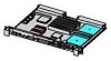
Customer Replaceable Unit (CRU) Physical Location Customer Replaceable Unit (CRU) Physical Location This section contains views of the rp24xx server. The locator numbers in the diagrams correspond to the numbers in the CRU Part Number section. 2 3 10 6 7 4 13 6 11 12 5 9 8 16 7 14 17 NOTE - HP A4500A | Hardware Manual - rp24xx, Customer Viewable - Page 154
Customer Replaceable Unit (CRU) Physical Location 2 Chapter - HP A4500A | Hardware Manual - rp24xx, Customer Viewable - Page 155
Units (CRUs) for the rp24xx server. CRUs may be removed or replaced by either the customer or by qualified HP field engineering personnel. Table 1 A6145-69001 36 GB Disk Drive A5570A A5570-60002 A5570-69002 Guardian Service Processor 9 Non Exchange CRUs Part # A5570-60003 A5570-60005 A5570- - HP A4500A | Hardware Manual - rp24xx, Customer Viewable - Page 156
Customer Replaceable Unit (CRU) Part Numbers 2 Chapter - HP A4500A | Hardware Manual - rp24xx, Customer Viewable - Page 157
bezel. WARNING Do not attempt to lift or carry the server by the bezel. The bezel is made of plastic and is attached to the server chassis by two bezel retainers and four ball-posts. It will only support the weight of the server chassis in an emergency. Failure to heed this warning may - HP A4500A | Hardware Manual - rp24xx, Customer Viewable - Page 158
Front Bezel Removal 230 Chapter - HP A4500A | Hardware Manual - rp24xx, Customer Viewable - Page 159
replace the bezel. WARNING Do not lift or carry the server by the bezel. The bezel is made of plastic and is attached to the server chassis by two bezel retainers and four ball-posts. It will only support the weight of the server chassis in an emergency. Failure to heed this warning may - HP A4500A | Hardware Manual - rp24xx, Customer Viewable - Page 160
Front Bezel Replacement 232 Chapter - HP A4500A | Hardware Manual - rp24xx, Customer Viewable - Page 161
that can cause serious injury or death. Step 2. Unfasten the two captive knurled thumbscrews located near the bottom edge of the front of the server cover. Step 3. Grasp the thumb screws and pull the cover toward you. Slide the cover approximately 2.5 MM (1 in.) then lift the cover front to - HP A4500A | Hardware Manual - rp24xx, Customer Viewable - Page 162
Server Cover Removal 234 Chapter - HP A4500A | Hardware Manual - rp24xx, Customer Viewable - Page 163
and seat it against the rear chassis panel. Step 3. Fasten the two captive knurled thumbscrews located near the bottom edge of the front of the server cover. CAUTION The server weighs approximately 23 kg (50 lbs). Take necessary precautions to prevent muscle strain when lifting and carrying the - HP A4500A | Hardware Manual - rp24xx, Customer Viewable - Page 164
Server Cover Replacement 236 Chapter - HP A4500A | Hardware Manual - rp24xx, Customer Viewable - Page 165
replaced while the server is running. NOTE MPE/iX does not support hotswap. Do not use these procedures on HP e3000 servers. The procedures in is being replaced. NOTE HP often uses different manufacturers for disks that have the same product number. The HotPlug manual procedure will not update - HP A4500A | Hardware Manual - rp24xx, Customer Viewable - Page 166
at the time the volume group was activated. Remove the bad disk as described in the HotPlug Hardware Procedure section, then follow the instructions in Disk Drive Replacement for replacing the disk and perform the Hot Swap Procedure for Unattached Physical Volumes described there. Otherwise, your - HP A4500A | Hardware Manual - rp24xx, Customer Viewable - Page 167
line. This lvreduce process will hang, and you will need terminal control to kill the command. Once the "successfully reduced" message has been generated, manually kill the process, using the kill -9 command. a. Use the ps command to find the PID for the lvreduce process. # ps -ef | grep lvreduce - HP A4500A | Hardware Manual - rp24xx, Customer Viewable - Page 168
using the lvlnboot command. # lvlnboot -R HotPlug Hardware Procedure CAUTION (MPE/iX does not support hotswap). Disk Drives can be removed or installed with the server still powered on. This is referred to as a "manual HotPlug". However, DO NOT remove a HotPlug disk drive until all prior software - HP A4500A | Hardware Manual - rp24xx, Customer Viewable - Page 169
HotPlug Disk Drive Removal (HPUX Systems Only) ccrr003 Chapter 241 - HP A4500A | Hardware Manual - rp24xx, Customer Viewable - Page 170
HotPlug Disk Drive Removal (HPUX Systems Only) 242 Chapter - HP A4500A | Hardware Manual - rp24xx, Customer Viewable - Page 171
and hardware procedures are followed, internal disk drives can be removed and replaced while the server is running. NOTE MPE/iX does not support hotplug. Do not use these procedures on HP e3000 servers. The procedures in this section are in two parts: physically replacing the device in the - HP A4500A | Hardware Manual - rp24xx, Customer Viewable - Page 172
this procedure if the disk that was removed was recognized as an attached physical volume. NOTE HP often uses different manufacturers for disks having the same product number. The HotPlug manual procedure will not update the disk drivers internal information to that of the replaced disk drive - HP A4500A | Hardware Manual - rp24xx, Customer Viewable - Page 173
Physical Volumes Follow these steps to replace a HotPlug disk drive for unattached physical volumes. NOTE HP often uses different manufacturers for disks having the same product number. The HotPlug manual procedure will not update the disk drivers internal information to that of the replaced disk - HP A4500A | Hardware Manual - rp24xx, Customer Viewable - Page 174
Run the mkboot command to make the device bootable. For example: #mkboot /dev/rdsk/cXtXdX Step 5. Use the mkboot command again to add the HP-UX auto-file string. For example: #mkboot -a "hpux" /dev/rdsk/cXtXdX Step 6. Run lvlnboot: #lvlnboot -R Step 7. Resynchronize the mirrors of the replaced disk - HP A4500A | Hardware Manual - rp24xx, Customer Viewable - Page 175
To remove the I/O Card Cage, follow the steps listed below: CAUTION Ensure that the system is shut down and power removed from the server before attempting removal or replacement of a component. Step 1. On the rear bulkhead, remove cables attached to I/O card slots 2 through 4, located inside the - HP A4500A | Hardware Manual - rp24xx, Customer Viewable - Page 176
I/O Card Cage Removal 1 6 7 2 3 8 5 9 4 ccrr005 No. Title 1 I/O Card Cage 2 I/O Card #1 slot tab 3 I/O Card #1 (short card only) 4 Top front captive screws 5 Flat lever handle 6 I/O Cards #2 through 4 slot tabs 7 I/O Cards #2 through 4 (long or short cards) 8 I/O Backplane retainer - HP A4500A | Hardware Manual - rp24xx, Customer Viewable - Page 177
Ensure that the system is shut down and power removed from the server before attempting removal or replacement of a component. Step 1. Grasp the card, plug the 5V power connector into the receptacle on the Guardian Service Protector card. The following photograph shows an empty I/O Card Cage. - HP A4500A | Hardware Manual - rp24xx, Customer Viewable - Page 178
I/O Card Cage Replacement 1 6 7 2 3 8 5 9 4 ccrr005 No. Title 1 I/O Card Cage 2 I/O Card #1 slot tab 3 I/O Card #1 (short card only) 4 Top front captive screws 5 Flat lever handle 6 I/O Cards #2 through 4 slot tabs 7 I/O Cards #2 through 4 (long or short cards) 8 I/O Backplane retainer - HP A4500A | Hardware Manual - rp24xx, Customer Viewable - Page 179
taken out of the chassis prior to removing these cards. PCI slot 1 supports a short PCI I/O card attached to the I/O Backplane and is located outside the Guardian Service Processor (GSP), front right side). • To remove PCI I/O cards 2, 3, and 4: a. Take the I/O card cage out of the server. b. Grasp - HP A4500A | Hardware Manual - rp24xx, Customer Viewable - Page 180
PCI I/O Card Removal 1 6 7 2 3 8 5 9 4 ccrr005 No. Title 1 I/O Card Cage 2 I/O Card #1 slot tab 3 I/O Card #1 (short card only) 4 Top front captive screws 5 Flat lever handle 6 I/O Cards #2 through 4 slot tabs 7 I/O Cards #2 through 4 (long or short cards) 8 I/O Backplane retainer - HP A4500A | Hardware Manual - rp24xx, Customer Viewable - Page 181
the chassis prior to replacing these cards. PCI slot 1 supports a short PCI I/O card attached to the I/O Backplane server. a. Take the I/O card cage out of the server. b. Orient the replacement I/O card in its guide power outlet (located on the Guardian Service Processor, front right side) after the - HP A4500A | Hardware Manual - rp24xx, Customer Viewable - Page 182
PCI I/O Card Replacement 1 6 7 2 3 8 5 9 4 ccrr005 No. Name No. Name 1 I/O Card Cage 6 I/O Card anchor screws 2 Outside I/O Card anchor screw 7 I/O Cards #2 through #4 3 Short I/O Card #1 (may be Secure Web Console) 8 I/O Backplane anchor screw 4 I/O Card Cage anchor quarter- - HP A4500A | Hardware Manual - rp24xx, Customer Viewable - Page 183
backplane inside the I/O card cage. CAUTION Ensure that the system is shut down and power removed from the server before attempting removal or replacement of a component. To remove the PCI backplane from the server, perform the following steps: Step 1. Remove the I/O cables from the back of the - HP A4500A | Hardware Manual - rp24xx, Customer Viewable - Page 184
PCI Backplane Removal 256 Chapter - HP A4500A | Hardware Manual - rp24xx, Customer Viewable - Page 185
4 are attached to the PCI backplane inside the I/O card cage. CAUTION Ensure that the system is shut down and power removed from the server before attempting removal or replacement of a component. To replace the PCI backplane, perform the following steps: Step 1. Lay the I/O card cage, open side - HP A4500A | Hardware Manual - rp24xx, Customer Viewable - Page 186
PCI Backplane Replacement 258 Chapter - HP A4500A | Hardware Manual - rp24xx, Customer Viewable - Page 187
sides of the System Board, next to the CPU assemblies. CAUTION DC-DC converter boards are not "hot-swap" or "hot-plug" units. Shut the server down and unplug the electrical connection prior to removing or replacing DC-DC converter boards. To remove a DC-DC Converter board and its slave(s) from - HP A4500A | Hardware Manual - rp24xx, Customer Viewable - Page 188
DC-DC Converter Removal ccrr010 272 Chapter - HP A4500A | Hardware Manual - rp24xx, Customer Viewable - Page 189
of the System Board, in front of the CPU assemblies. CAUTION DC-DC converter boards are not "hot-swap" or "hot-plug" units. Shut the server down and unplug the electrical connection prior to removing or replacing DC-DC converter boards. To replace a DC-DC Converter board and its slave(s) from - HP A4500A | Hardware Manual - rp24xx, Customer Viewable - Page 190
DC-DC Converter Replacement ccrr010 274 Chapter - HP A4500A | Hardware Manual - rp24xx, Customer Viewable - Page 191
is unseated, pull it up and out of the System Board. The following picture shows a memory DIMM located on the right side (from the server front) of the server system board. The next graphic is a drawing of a generic memory DIMM, followed by drawings that show DIMM removal/replacement. Chapter 275 - HP A4500A | Hardware Manual - rp24xx, Customer Viewable - Page 192
Memory DIMM Removal 276 Chapter - HP A4500A | Hardware Manual - rp24xx, Customer Viewable - Page 193
CAUTION Ensure that the system is shut down and power removed from the server before attempting removal or replacement of a component. To replace a memory DIMM DIMM when seating it. Step 1. Match the guide slots on the bottom of the DIMM with the guides on the socket and seat the memory DIMM into - HP A4500A | Hardware Manual - rp24xx, Customer Viewable - Page 194
Memory DIMM Replacement 278 Chapter - HP A4500A | Hardware Manual - rp24xx, Customer Viewable - Page 195
Processor (GSP) Removal Guardian Service Processor (GSP) Removal The GSP card resides on the System Board at the rear left center, under the short PCI I/O card (slot 1), which must be removed for access. Before removing the GSP from the server, perform the following steps: CAUTION Ensure that - HP A4500A | Hardware Manual - rp24xx, Customer Viewable - Page 196
Guardian Service Processor (GSP) Removal 288 Chapter - HP A4500A | Hardware Manual - rp24xx, Customer Viewable - Page 197
Processor Replacement Guardian Service Processor Replacement The GSP card resides on the System Board at the rear left center, under the mounting screws that hold the GSP card in place. The following picture shows a GSP installed in a server. The following graphic shows the location of a GSP in the - HP A4500A | Hardware Manual - rp24xx, Customer Viewable - Page 198
Guardian Service Processor Replacement 290 Chapter - HP A4500A | Hardware Manual - rp24xx, Customer Viewable - Page 199
three configurations: rack-mounted, stacked, or stand-alone. Access to servers mounted in an HP-supported rack is covered in this section. NOTE Ensure that there is enough area (Approximately 82 centimeters (32 in.) to fully extend the server out the front and work on it. WARNING Ensure that all - HP A4500A | Hardware Manual - rp24xx, Customer Viewable - Page 200
Extend a Server From the Rack 296 Chapter - HP A4500A | Hardware Manual - rp24xx, Customer Viewable - Page 201
are available in three configurations: rack-mounted, stacked, or stand-alone. Access to servers mounted in an HP-supported rack is covered in this section. To return the server into the rack, perform the following steps: Step 1. Push and hold each rail clip in to unlock the rail from the fully - HP A4500A | Hardware Manual - rp24xx, Customer Viewable - Page 202
Insert the Server into the Rack 298 Chapter
-
 1
1 -
 2
2 -
 3
3 -
 4
4 -
 5
5 -
 6
6 -
 7
7 -
8
-
9
-
10
-
11
-
12
-
13
-
14
-
15
-
16
-
17
-
18
-
19
-
20
-
21
-
22
-
23
-
24
-
25
-
26
-
27
-
28
-
29
-
30
-
31
-
32
-
33
-
34
-
35
-
36
-
37
-
38
-
39
-
40
-
41
-
42
-
43
-
44
-
45
-
46
-
47
-
48
-
49
-
50
-
51
-
52
-
53
-
54
-
55
-
56
-
57
-
58
-
59
-
60
-
61
-
62
-
63
-
64
-
65
-
66
-
67
-
68
-
69
-
70
-
71
-
72
-
73
-
74
-
75
-
76
-
77
-
78
-
79
-
80
-
81
-
82
-
83
-
84
-
85
-
86
-
87
-
88
-
89
-
90
-
91
-
92
-
93
-
94
-
95
-
96
-
97
-
98
-
99
-
100
-
101
-
102
-
103
-
104
-
105
-
106
-
107
-
108
-
109
-
110
-
111
-
112
-
113
-
114
-
115
-
116
-
117
-
118
-
119
-
120
-
121
-
122
-
123
-
124
-
125
-
126
-
127
-
128
-
129
-
130
-
131
-
132
-
133
-
134
-
135
-
136
-
137
-
138
-
139
-
140
-
141
-
142
-
143
-
144
-
145
-
146
-
147
-
148
-
149
-
150
-
151
-
152
-
153
-
154
-
155
-
156
-
157
-
158
-
159
-
160
-
161
-
162
-
163
-
164
-
165
-
166
-
167
-
168
-
169
-
170
-
171
-
172
-
173
-
174
-
175
-
176
-
177
-
178
-
179
-
180
-
181
-
182
-
183
-
184
-
185
-
186
-
187
-
188
-
189
-
190
-
191
-
192
-
193
-
194
-
195
-
196
-
197
-
198
-
199
-
200
-
201
-
202
 |
 |

rp24xx Hardware Manual