HP A6152n Upgrading and Servicing Guide
HP A6152n - Pavilion - 3 GB RAM Manual
 |
UPC - 883585142743
View all HP A6152n manuals
Add to My Manuals
Save this manual to your list of manuals |
HP A6152n manual content summary:
- HP A6152n | Upgrading and Servicing Guide - Page 1
Upgrading and Servicing Guide - HP A6152n | Upgrading and Servicing Guide - Page 2
Hewlett-Packard products and services are set forth in the express statements accompanying such products and services. Nothing herein should be construed as constituting an additional warranty. HP United States and/or other countries/regions. HP supports lawful use of technology and does not endorse - HP A6152n | Upgrading and Servicing Guide - Page 3
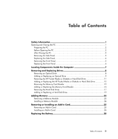
Information 1 Opening and Closing the PC 1 Preparing the PC 2 Before Opening the PC 2 After Closing the PC 3 Removing the Side Panel or Replacing the HP Pocket Media or Diskette or Hard Disk Drive 13 Removing the Memory Card Reader 15 Adding or Replacing the Memory Card Reader 16 Removing - HP A6152n | Upgrading and Servicing Guide - Page 4
iv Table of Contents - HP A6152n | Upgrading and Servicing Guide - Page 5
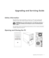
Information" in the Warranty and Support Guide before installing and connecting your system to the electrical power system. The Upgrading and Servicing Guide provides instructions on how to remove and replace hardware components of your PC. Opening and Closing the PC Upgrading and Servicing Guide 1 - HP A6152n | Upgrading and Servicing Guide - Page 6
service the PC numbers, all installed options, and other information about the system. It's easier to consult this information than to open and examine the PC PC from the power source before removing the front and side panels of the PC. Failure to do so before you open the PC of the PC or optional - HP A6152n | Upgrading and Servicing Guide - Page 7
as the monitor. 5 If you installed an add-in card, install any software drivers supplied by the card manufacturer. Removing the Side Panel 1 See "Before Opening the PC" on page 2. 2 Loosen the thumbscrew (A) that secures the side panel to the PC chassis. You may need to use a screwdriver the first - HP A6152n | Upgrading and Servicing Guide - Page 8
attached properly. 2 Ensure that the hole for the thumbscrew aligns with the hole in the chassis, and then replace the thumbscrew (A). 3 See "After Closing the PC" on page 3. 4 Upgrading and Servicing Guide - HP A6152n | Upgrading and Servicing Guide - Page 9
Removing the Front Panel This procedure is necessary only when removing or replacing an optical drive, memory card reader, an HP Pocket Media Drive, diskette drive, or the hard disk drive. 1 Pull the three tabs (B) away from the outside edge of the chassis. B 2 Swing the front - HP A6152n | Upgrading and Servicing Guide - Page 10
right side of the front panel into the three holes on the right side of the chassis until the panel snaps into place. 6 Upgrading and Servicing Guide - HP A6152n | Upgrading and Servicing Guide - Page 11
drive (select models) E Front connector panel (no replacement instructions) F Hard disk drive and space for a second hard disk drive (located inside the chassis) (select models) NOTE: The connectors and components of your chassis model may vary from the illustration. Upgrading and Servicing Guide 7 - HP A6152n | Upgrading and Servicing Guide - Page 12
and drivers for the PC" on page 1. 2 Release the drive by pulling the latch out away from the chassis and then pulling the drive part way out of the front of the chassis. (The latch drive brackets secure the drives in their respective positions in the chassis.) 8 Upgrading and Servicing Guide - HP A6152n | Upgrading and Servicing Guide - Page 13
3 Disconnect the power, data, and the sound cable, if available, from the back of the optical drive you want to remove. For most drive cables, plate slot (B) and rotate the screwdriver to break the knockout plate out of the front cover. Discard the knockout plate. A B Upgrading and Servicing Guide 9 - HP A6152n | Upgrading and Servicing Guide - Page 14
part way into the front of the chassis. (The latch drive brackets secure the drives in their respective positions in the chassis.) 10 Upgrading and Servicing Guide - HP A6152n | Upgrading and Servicing Guide - Page 15
6 Connect the power and data cables from the back of the optical PC" on page 1. 2 Release the HP Pocket Media or diskette (floppy), or hard disk drive, by removing the two screws on the side of the drive, and then slide the drive part way out of the front of the chassis. Upgrading and Servicing Guide - HP A6152n | Upgrading and Servicing Guide - Page 16
3 Disconnect the power and data cables from the back of the drive by squeezing the two latches and pulling the cable. MASTER SLAVE To CPU 4 Pull the drive out through the front of the chassis. 12 Upgrading and Servicing Guide - HP A6152n | Upgrading and Servicing Guide - Page 17
HP Pocket Media, diskette (floppy), or hard disk drive, if necessary. See "Removing the HP Pocket Media or Diskette or Hard Disk Drive" on page 11. 2 Slide the HP the side of the drive, and then attach the two screws. For the HP Pocket Media and diskette (floppy) drive, make sure to insert the screw - HP A6152n | Upgrading and Servicing Guide - Page 18
a primary hard disk drive. B - Connect to a secondary hard disk drive (select models only). C - Connect to the PC motherboard. 5 Complete the procedures to replace the front panel, replace the side panel, and close the PC. See "Opening and Closing the PC" on page 1. 14 Upgrading and Servicing Guide - HP A6152n | Upgrading and Servicing Guide - Page 19
card reader, sliding the reader to the left to loosen it, and then pulling the memory card reader part way out of the front of the chassis. 3 Disconnect the cable from the back of the memory card reader. 4 Pull the memory card reader out of the front of the chassis. Upgrading and Servicing Guide - HP A6152n | Upgrading and Servicing Guide - Page 20
hole on the top of the memory card reader, and then insert the short screw to secure the memory card reader to the chassis. 5 Complete the procedures to replace the front panel, replace the side panel, and close the PC. See "Opening and Closing the PC" on page 1. 16 Upgrading and Servicing Guide - HP A6152n | Upgrading and Servicing Guide - Page 21
remove the side panel and to remove the front panel. See "Opening and Closing the PC" on page 1. 2 Lay the computer gently on its side. 3 Remove the two screws that secure the hard disk the hard disk drive cage away from the bottom of the chassis as shown below. Upgrading and Servicing Guide 17 - HP A6152n | Upgrading and Servicing Guide - Page 22
drive connector. 6 5 2 1 Disconnecting the Serial ATA hard disk drive cables MASTER SLAVE To CPU Disconnecting the Parallel ATA hard disk drive cables 18 Upgrading and Servicing Guide - HP A6152n | Upgrading and Servicing Guide - Page 23
disk drive cables are facing the top of the drive cage. NOTE: If you are replacing an old drive with a new drive, remove the four guide screws from the old drive, and use the screws to install the new drive. If you are installing a second hard disk drive, use four standard - HP A6152n | Upgrading and Servicing Guide - Page 24
the chassis. The two screw holes on the hard disk drive cage (A) should be aligned with the screw holes on the chassis (B). A B 4 Align the four guides on the bottom of the hard disk drive cage with the holes on the back of the chassis, and then slide it down toward the - HP A6152n | Upgrading and Servicing Guide - Page 25
models only). C - Connect to the PC motherboard. 6 Attach the two screws that secure the hard disk drive cage to the chassis. 7 Complete the procedures to replace the front panel, replace the side panel, and close the PC. See "Opening and Closing the PC" on page 1. Upgrading and Servicing Guide 21 - HP A6152n | Upgrading and Servicing Guide - Page 26
and speed of memory module your PC uses, and for specific memory module information and specifications, go to the Web site listed in your Warranty and Support Guide, and click the Support link. WARNING: Using the wrong type of memory module could damage the system. 22 Upgrading and Servicing Guide - HP A6152n | Upgrading and Servicing Guide - Page 27
the procedures to prepare the PC and to remove the side panel. See "Opening and Closing the PC" on page 1. 2 Gently lay the PC on its side. 3 Locate the memory sockets on the motherboard. CAUTION: When handling a 6 Lift the memory module from the memory socket. Upgrading and Servicing Guide 23 - HP A6152n | Upgrading and Servicing Guide - Page 28
same type and speed as the memory originally installed in your PC. CAUTION: When handling a memory module, be careful not upright. 3 Complete the procedures to replace the side panel, and close the PC. See "Opening and Closing the PC" on page 1. NOTE: If a blank screen is displayed after replacing - HP A6152n | Upgrading and Servicing Guide - Page 29
. A flat-head and a Phillips screwdriver are needed to remove, replace, or add an add-in card. NOTE: A power supply upgrade may be required for certain graphics card upgrades. Check with the graphics card supplier for more information about power supply requirements. Upgrading and Servicing Guide 25 - HP A6152n | Upgrading and Servicing Guide - Page 30
. See "Opening and Closing the PC" on page 1. 2 Gently lay the PC on its side. 3 On the back of the PC, remove the screw from the bracket cover for the add-in card slots, and then remove the bracket cover. 4 Inside the PC, locate the add-in card slots on the motherboard. WARNING: Be careful of the - HP A6152n | Upgrading and Servicing Guide - Page 31
and close the PC. See "Opening and Closing the PC" on page 1. NOTE: If the new card or device isn't working, read through the card manufacturer's installation instructions and recheck all connections, including those to the card, power supply, keyboard, and monitor. Upgrading and Servicing Guide 27 - HP A6152n | Upgrading and Servicing Guide - Page 32
motherboard provides backup power for the PC instructions. 1 Complete the procedures to prepare the PC and to remove the side panel. See "Opening and Closing the PC" on page 1. 2 Gently lay the PC PC. See "Opening and Closing the PC" on page 1. 28 Upgrading and Servicing Guide Part number: 5991-6989
-
 1
1 -
 2
2 -
 3
3 -
 4
4 -
 5
5 -
 6
6 -
 7
7 -
8
-
9
-
10
-
11
-
12
-
13
-
14
-
15
-
16
-
17
-
18
-
19
-
20
-
21
-
22
-
23
-
24
-
25
-
26
-
27
-
28
-
29
-
30
-
31
-
32
 |
 |

Upgrading and Servicing Guide