HP BL465c Electrical signal integrity considerations for HP BladeSystem
HP BL465c - ProLiant - 2 GB RAM Manual
 |
UPC - 882780893504
View all HP BL465c manuals
Add to My Manuals
Save this manual to your list of manuals |
HP BL465c manual content summary:
- HP BL465c | Electrical signal integrity considerations for HP BladeSystem - Page 1
considerations for HP BladeSystem technology brief Introduction...2 What is signal integrity ...2 Challenges...4 Significant factors affecting signal integrity 6 Dielectric losses ...6 Skin effect ...6 Impedance discontinuities ...6 Stubs ...7 Crosstalk...8 Design goals ...9 Target fabrics ...10 - HP BL465c | Electrical signal integrity considerations for HP BladeSystem - Page 2
support upcoming technologies and increasing demand for bandwidth and power document the electrical requirements for the high-speed interfaces of the HP BladeSystem. This applies to all HP BladeSystem switch modules, mezzanine cards, server blades low bit rates However, at high bit rates and over - HP BL465c | Electrical signal integrity considerations for HP BladeSystem - Page 3
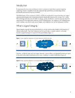
As signal speeds increase additional effects inherent in the transmission media environment emerge as inhibitors to successful signal delivery. These effects include: • the physical characteristics of the material used for transmission, including materials adjoining the transmission media • the - HP BL465c | Electrical signal integrity considerations for HP BladeSystem - Page 4
rates of up to 10 Gb/s. Each half-height server blade has the cross-sectional bandwidth to conduct up to 160 Gb/s per direction. In a c7000 enclosure fully configured with 16 half-height server blades of the transmission. The "eye" in the eye diagram is shown in Figure 4; it is the opening in - HP BL465c | Electrical signal integrity considerations for HP BladeSystem - Page 5
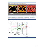
Figure 4. Measured eye diagrams from a 40" PCI-Compliance ISI trace Increasing frequency significantly increases attenuation. Skin resistive loss and dielectric loss are the primary components of frequency-dependent attenuation, as shown in Figure 5. Figure 5. Frequency dependent attenuation 5 - HP BL465c | Electrical signal integrity considerations for HP BladeSystem - Page 6
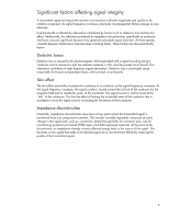
Significant factors affecting signal integrity A transmitted signal arriving at the receiver must maintain sufficient magnitude and quality to be reliably recognized. As signal frequency increases, previously inconsequential factors emerge as new obstacles. Line bandwidth is affected by attenuation - HP BL465c | Electrical signal integrity considerations for HP BladeSystem - Page 7
return to the trace after the delay of going down and back. This reflected signal is added to the traveling signal. At high enough data rates this delay is long enough compared to the bit length to adversely affect a portion of the next bit. This distorts the signal waveform. Figure 6. Cross - HP BL465c | Electrical signal integrity considerations for HP BladeSystem - Page 8
Crosstalk As current moves through a conductor it creates an electromagnetic field. When two (or more) conductors run parallel to each other, the inductive and capacitive coupling between the paths can lead to interference. This interference is also known as crosstalk. Essentially, crosstalk is the - HP BL465c | Electrical signal integrity considerations for HP BladeSystem - Page 9
a high-speed signal midplane that provides the flexibility to intermingle server blades and interconnect fabrics in many ways to solve a multitude of designed and built to ensure that it can support upcoming technologies and their demand for bandwidth and power for at least five to seven years. - HP BL465c | Electrical signal integrity considerations for HP BladeSystem - Page 10
c-Class architecture must support dozens of server blades, more than 50 Mezzanine Cards (MEZZ) and I/O modules, and multiple enclosure designs. Target fabrics The HP BladeSystem provides high-speed interfaces between server blades and switch modules. Server blades may contain components connected - HP BL465c | Electrical signal integrity considerations for HP BladeSystem - Page 11
reflected the physical system. The team then created an extensive documentation/specification library and server blades and interconnect modules. To aid in the design of the signal midplane, HP involved the same signal integrity experts that design the HP Superdome computers. Specifically, HP - HP BL465c | Electrical signal integrity considerations for HP BladeSystem - Page 12
) are required to meet the electrical specifications developed by HP, allowing separate vendors to create interoperable parts of the channel. The server blade vendor must ensure that any channel terminating at an IC on the server blade meets the same requirements as the combined effects of the - HP BL465c | Electrical signal integrity considerations for HP BladeSystem - Page 13
to a trace, see Figure 12. Test pads should not be used. Figure 12. Remove non-functional pads Using data from a fiber weave investigation HP determined that the differences found among PCB fiber weaves were large enough at 10Gb/s to affect signal integrity. For designs that expect to operate at - HP BL465c | Electrical signal integrity considerations for HP BladeSystem - Page 14
of a board for more than two inches of cumulative distance. The length of trace segments that are parallel to the edge of a board should be minimized as much as possible. Traces should be at an angle of at least 10º to a board edge. This is to reduce the effects of PCB fiber weave on board impedance - HP BL465c | Electrical signal integrity considerations for HP BladeSystem - Page 15
was designed to ensure that it could support new high-speed technologies and their demand for both bandwidth and power for at least 5 to 7 years the models accurately reflected the physical system. HP created and maintains an extensive documentation/specification library that with adherence yields - HP BL465c | Electrical signal integrity considerations for HP BladeSystem - Page 16
www.hp.com/servers/technology www.hp.com/go/bladesystem Call to action Send comments about this paper to [email protected]. © 2009 Hewlett-Packard Development Company, L.P. The information contained herein is subject to change without notice. The only warranties for HP products and services are
-
 1
1 -
 2
2 -
 3
3 -
 4
4 -
 5
5 -
 6
6 -
 7
7 -
8
-
9
-
10
-
11
-
12
-
13
-
14
-
15
-
16
 |
 |

Electrical signal integrity considerations for
HP BladeSystem
technology brief
Introduction
.........................................................................................................................................
2
What is signal integrity
........................................................................................................................
2
Challenges
..........................................................................................................................................
4
Significant factors affecting signal integrity
.............................................................................................
6
Dielectric losses
...............................................................................................................................
6
Skin effect
.......................................................................................................................................
6
Impedance discontinuities
.................................................................................................................
6
Stubs
..............................................................................................................................................
7
Crosstalk
.........................................................................................................................................
8
Design goals
.......................................................................................................................................
9
Target fabrics
................................................................................................................................
10
Infrastructure architecture
................................................................................................................
10
Implementation
..................................................................................................................................
11
Specification library
.......................................................................................................................
12
Board trace lengths
........................................................................................................................
12
Board layout and materials
.............................................................................................................
12
Summary
..........................................................................................................................................
15
For more information
..........................................................................................................................
16
Call to action
....................................................................................................................................
16