HP Chromebox G3 Maintenance and Service Guide
HP Chromebox G3 Manual
 |
View all HP Chromebox G3 manuals
Add to My Manuals
Save this manual to your list of manuals |
HP Chromebox G3 manual content summary:
- HP Chromebox G3 | Maintenance and Service Guide - Page 1
Maintenance and Service Guide SUMMARY This guide provides information about spare parts, removal and replacement of parts, security, backing up, and more. - HP Chromebox G3 | Maintenance and Service Guide - Page 2
a trademark owned by its proprietor and used by HP Inc. under license. Chrome, Chromebox, and Google, are trademarks of Google LLC. available on your Chromebook. To access the latest user guides, go to http://www.hp.com/support, and follow the instructions to find your product. Then select Manuals - HP Chromebox G3 | Maintenance and Service Guide - Page 3
...5 Front ...6 Rear ...7 Bottom ...8 Labels ...9 3 Illustrated parts catalog ...13 Chromebox major components ...13 Miscellaneous parts ...15 4 Removal and replacement procedures preliminary requirements 17 Tools required ...17 Service considerations ...18 Plastic parts ...18 Cables and connectors - HP Chromebox G3 | Maintenance and Service Guide - Page 4
Bottom cover ...27 I/O side frame ...28 Bottom shield ...29 Power connector cable ...30 WLAN module ...31 Solid-state drive ...33 Memory module ...33 System board ...35 Fan ...37 Heat sink ...38 Top shield ...39 Power button board ...40 7 Specifications ...43 Chromebook specifications ...43 Solid- - HP Chromebox G3 | Maintenance and Service Guide - Page 5
and their descriptions Category Description Product Name HP Chromebox G3 Processors ● Intel™ Core® i7-1061U Intel Pentium, or Intel Celeron processor Media card reader HP 3-in-1 card reader Memory DDR4-2666 dual-channel SODIMM support Supports the following configurations: ● 16 GB (2 × 8 - HP Chromebox G3 | Maintenance and Service Guide - Page 6
requirements AC adapters: ● 90 W HP Smart Adapter (4.5 mm) ● 90 W HP Smart Adapter (PFC, standard barrel, right angle, 4.5 mm) ● 65 W HP Smart Adapter (non-PFC, EM, standard barrel, 4.5 mm) ● 65 W HP Smart Adapter (non-PFC, EM, standard barrel, 4.5 mm) ● 65 W HP Smart Adapter (non-PFC, standard - HP Chromebox G3 | Maintenance and Service Guide - Page 7
Table 1-1 Product components and their descriptions (continued) Category Description Operating system Chrome 64 Serviceability End user replaceable part: AC adapter ENWW 3 - HP Chromebox G3 | Maintenance and Service Guide - Page 8
4 Chapter 1 Product description ENWW - HP Chromebox G3 | Maintenance and Service Guide - Page 9
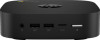
table to identify the components on the right side of the Chromebox. Table 2-1 Right-side components and their descriptions Component (1) stored on your device, such as photos, downloaded files, and saved networks. HP recommends that you save files to an external hard drive, USB flash drive, or - HP Chromebox G3 | Maintenance and Service Guide - Page 10
. Also connects an optional headset microphone. This jack does not support optional standalone microphones. WARNING! To reduce the risk of personal Notices. NOTE: When a device is connected to the jack, the Chromebox™ speakers are disabled. (2) USB SuperSpeed charging port Connects a USB - HP Chromebox G3 | Maintenance and Service Guide - Page 11
optional memory cards that store, manage, share, or access information. To insert a card: 1. Hold the card label-side up, with the connectors facing the Chromebox. 2. Insert the card into the memory card reader, and then press in on the card until it is firmly seated. To remove a card: ▲ Press - HP Chromebox G3 | Maintenance and Service Guide - Page 12
USB Type-A SuperSpeed port Connects a USB device, provides data transfer, and (for select products) charges small devices (such as a smartphone) when the Chromebox is on or in Sleep mode. NOTE: Use a standard USB Type-A charging cable or cable adapter (purchased separately) when charging a small - HP Chromebox G3 | Maintenance and Service Guide - Page 13
troubleshooting system problems or traveling internationally with the device. Labels can be in paper form or imprinted on the product. IMPORTANT: Check the bottom of the Chromebox for the correct label. ● Service label-Provides important information to identify your device. When contacting support - HP Chromebox G3 | Maintenance and Service Guide - Page 14
The following label below represents Asia Pacific and Japan 1 countries and regions. The following label below represents Asia Pacific and Japan 2 countries and regions. 10 Chapter 2 Getting to know your Chromebox ENWW - HP Chromebox G3 | Maintenance and Service Guide - Page 15
● Regulatory labels-Provide regulatory information about the device. ● Wireless certification labels-Provide information about optional wireless devices and the approval markings for the countries or regions in which the devices have been approved for use. ENWW Labels 11 - HP Chromebox G3 | Maintenance and Service Guide - Page 16
12 Chapter 2 Getting to know your Chromebox ENWW - HP Chromebox G3 | Maintenance and Service Guide - Page 17
current information about supported parts for your Chromebox, go to http://partsurfer.hp.com, select your country or region, and then follow the on-screen instructions. NOTE: Details about your Chromebox, including model, serial number, product key, and length of warranty, are on the service tag at - HP Chromebox G3 | Maintenance and Service Guide - Page 18
Table 3-1 Chromebox major component descriptions and part numbers Item Component Spare part number spare part kit does not include the power button board cable. The power button board cable is available using spare part number M42089-001. (3b) Power button board cable M42089-001 (4) Fan ( - HP Chromebox G3 | Maintenance and Service Guide - Page 19
Table 3-1 Chromebox major component descriptions and part numbers (continued) Item Component Miscellaneous part descriptions and part numbers Component AC adapter: 90 W AC adapter (PFC, S-3P, 4.5 mm) 65 W HP Smart Adapter (non-PFC, EM, RC, 4.5 mm) 65 W AC adapter (non-PFC, S-3P, 4.5 mm) Power - HP Chromebox G3 | Maintenance and Service Guide - Page 20
16 Chapter 3 Illustrated parts catalog ENWW - HP Chromebox G3 | Maintenance and Service Guide - Page 21
4 Removal and replacement procedures preliminary requirements Use this information to properly prepare to disassemble and reassemble the Chromebox. Tools required You need the following tools to complete the removal and replacement procedures: ● Tweezers ● Case utility tool or similar thin, - HP Chromebox G3 | Maintenance and Service Guide - Page 22
during disassembly and reassembly can damage plastic parts. Cables and connectors Handle cables with extreme care to avoid damage. IMPORTANT: When servicing the Chromebox, be sure that cables are placed in their proper locations during the reassembly process. Improper cable placement can damage the - HP Chromebox G3 | Maintenance and Service Guide - Page 23
material. ● Use a wrist strap connected to a properly grounded work surface and use properly grounded tools and equipment. ● Use conductive field service tools, such as cutters, screw drivers, and vacuums. ● When fixtures must directly contact dissipative surfaces, use fixtures made only of static - HP Chromebox G3 | Maintenance and Service Guide - Page 24
20 Chapter 4 Removal and replacement procedures preliminary requirements ENWW - HP Chromebox G3 | Maintenance and Service Guide - Page 25
5 Electrostatic discharge information A sudden discharge of static electricity from your finger or other conductor can destroy static-sensitive devices or microcircuitry. Often the spark is neither felt nor heard, but damage occurs. An electronic device exposed to electrostatic discharge (ESD) - HP Chromebox G3 | Maintenance and Service Guide - Page 26
Table 5-1 Static electricity occurrence based on activity and humidity (continued) Relative humidity Removing DIPs from vinyl tray 2,000 V 4,000 V Removing DIPs from polystyrene foam 3,500 V 5,000 V Removing bubble pack from PCB (printed circuit board) 7,000 V 20,000 V Packing PCBs in - HP Chromebox G3 | Maintenance and Service Guide - Page 27
with pins, leads, or circuitry. Recommended materials and equipment HP recommends certain materials and equipment to prevent static electricity. Static-dissipative table or floor mats with hard tie to ground ● Field service kits ● Static awareness labels ● Wrist straps and footwear straps providing - HP Chromebox G3 | Maintenance and Service Guide - Page 28
● Material handling packages ● Conductive plastic bags ● Conductive plastic tubes ● Conductive tote boxes ● Opaque shielding bags ● Transparent metallized shielding bags ● Transparent shielding tubes 24 Chapter 5 Electrostatic discharge information ENWW - HP Chromebox G3 | Maintenance and Service Guide - Page 29
provider parts. IMPORTANT: Components described in this chapter should be accessed only by an authorized service provider. Accessing these parts can damage the Chromebook or void the warranty. NOTE: Details about your Chromebook, including model, serial number, product key, and length - HP Chromebox G3 | Maintenance and Service Guide - Page 30
. For complete and current information about supported parts for your Chromebook, go to http://partsurfer.hp.com, select your country or region, and then follow the on-screen instructions. You must remove, replace, or loosen as many as 30 screws when you service the parts described in this chapter - HP Chromebox G3 | Maintenance and Service Guide - Page 31
for disassembly (Preparation for disassembly on page 27). Remove the bottom cover: 1. Position the Chromebox upside down with the rear toward you. 2. Remove the four rubber feet (1). The rubber feet are available in the Rubber Feet Kit, spare part number L17271-001. 3. Remove the four Phillips M2 - HP Chromebox G3 | Maintenance and Service Guide - Page 32
: 1. Remove the two Phillips M2.5 × 5.0 screws (1) that secure the I/O side frame to the Chromebox. 2. Detach the bottom shield rear protective strip (2) from the I/O side frame and bottom shield. (The -001. 28 Chapter 6 Removal and replacement procedures for authorized service provider parts ENWW - HP Chromebox G3 | Maintenance and Service Guide - Page 33
frame on page 28). Remove the bottom shield: 1. Remove the four Phillips M2.5 × 5.0 screws (1) that secure the bottom shield to the Chromebox. 2. Detach the bottom shield front protective strip (2) and the bottom shield padding (3) from the bottom shield. (The bottom shield front protective strip - HP Chromebox G3 | Maintenance and Service Guide - Page 34
removing the power connector cable, follow these steps: 1. Prepare the Chromebox for disassembly (Preparation for disassembly on page 27). 2. Remove the power connector cable bracket (2). The power connector cable bracket is available using spare part number M42090-001. 4. Remove the power connector - HP Chromebox G3 | Maintenance and Service Guide - Page 35
(4). If the gasket needs to be replaced, it is available using spare part number L17265-001. Reverse this procedure to functionality, and then contact technical support. Before removing the WLAN module, follow these steps: 1. Prepare the Chromebox for disassembly (Preparation for disassembly on - HP Chromebox G3 | Maintenance and Service Guide - Page 36
the antenna connector, as shown in the following illustration. Reverse this procedure to install the WLAN module. 32 Chapter 6 Removal and replacement procedures for authorized service provider parts ENWW - HP Chromebox G3 | Maintenance and Service Guide - Page 37
drive Solid-state drive absorber Spare part number M11040-005 M24278-001 Before removing the solid-state drive, follow these steps: 1. Prepare the Chromebox for disassembly (Preparation for disassembly on page 27). 2. Remove the bottom cover (Bottom cover on page 27). 3. Remove the I/O side frame - HP Chromebox G3 | Maintenance and Service Guide - Page 38
the memory module, follow these steps: 1. Prepare the Chromebox for disassembly (Preparation for disassembly on page 27). of the memory module shield and remove the shield (2). The memory module shield is available using spare part number L17264-001. NOTE: When installing the memory module shield, - HP Chromebox G3 | Maintenance and Service Guide - Page 39
2. Spread the two retention clips outward (1) until the memory module tilts up at a 45° angle, and then remove the module (2). Use the same procedure to remove all memory modules. IMPORTANT: To prevent damage to the memory module, hold the memory module by the edges only. Do not touch the components - HP Chromebox G3 | Maintenance and Service Guide - Page 40
1. Prepare the Chromebox for disassembly (Preparation for disassembly on page 27). 2. Remove the bottom cover (Bottom cover on page 27). 3. Remove the power button board cable (2) from the system board. 36 Chapter 6 Removal and replacement procedures for authorized service provider parts ENWW - HP Chromebox G3 | Maintenance and Service Guide - Page 41
and part number Description Fan (includes cable) Spare part number M24727-001 Before removing the fan, follow these steps: 1. Prepare the Chromebox for disassembly (Preparation for disassembly on page 27). 2. Remove the bottom cover (Bottom cover on page 27), and then remove the following - HP Chromebox G3 | Maintenance and Service Guide - Page 42
part number M24726-001 Before removing the heat sink, follow these steps: 1. Prepare the Chromebox for disassembly (Preparation for disassembly on page 27). 2. Remove the bottom cover (Bottom on page 37). 38 Chapter 6 Removal and replacement procedures for authorized service provider parts ENWW - HP Chromebox G3 | Maintenance and Service Guide - Page 43
Remove the heat sink: 1. Remove the four Phillips M2.0 × 4.0 screws (1) that secure the heat sink to the system board. 2. Remove the heat sink (2). Each time the heat sink is removed, thoroughly clean the thermal material from the processor component (1) and the surface of the heat sink (2). - HP Chromebox G3 | Maintenance and Service Guide - Page 44
number M24724-001 Before removing the power button board, follow these steps: 1. Prepare the Chromebox for disassembly (Preparation for disassembly on page 27). 2. Remove the bottom cover (Bottom page 39). 40 Chapter 6 Removal and replacement procedures for authorized service provider parts ENWW - HP Chromebox G3 | Maintenance and Service Guide - Page 45
necessary to replace the power button board cable, disconnect the cable from the connector (3) on the power button board. The power button board cable is available using spare part number M42089-001. Reverse this procedure to install the power button board. ENWW Component replacement procedures 41 - HP Chromebox G3 | Maintenance and Service Guide - Page 46
42 Chapter 6 Removal and replacement procedures for authorized service provider parts ENWW - HP Chromebox G3 | Maintenance and Service Guide - Page 47
7 Specifications This chapter provides specifications for your Chromebox. Chromebook specifications This section provides specifications for your Chromebook. When traveling with your Chromebook, the Chromebook dimensions and weights, as well as input power ratings - HP Chromebox G3 | Maintenance and Service Guide - Page 48
Table 7-1 Chromebook specifications (continued) Metric U.S. Operating voltage and current 5 V dc @ 2 A / 12 V dc @ 3 A /15 V dc @ 3 A - 45 W USB-C® 5 V dc @ 3 A / 9 V dc @ 3 A / 12 V dc @ 3.75 A /15 V dc @ 3 A - 45 W USB-C 5 V dc @ 3 A / 9 V dc @ 3 A / 10 V dc @ 3.75 A / 12 V dc @ 3.75 A / 15 - HP Chromebox G3 | Maintenance and Service Guide - Page 49
when referring to hard drive storage capacity. Actual accessible capacity is less. Actual drive specifications may differ slightly. NOTE: Certain restrictions and exclusions apply. Contact support for details. ENWW Solid-state drive specifications 45 - HP Chromebox G3 | Maintenance and Service Guide - Page 50
46 Chapter 7 Specifications ENWW - HP Chromebox G3 | Maintenance and Service Guide - Page 51
ac, or from 220 V ac to 240 V ac. The 3-conductor power cord set included with the Chromebox meets the requirements for use in the country or region where the equipment is purchased. Power cord sets 1 Australia SAA 1 Austria OVE 1 Belgium CEBEC 1 Brazil ABNT 1 Canada CSA 2 ENWW 47 - HP Chromebox G3 | Maintenance and Service Guide - Page 52
Table 8-1 Power cord requirements for specific countries and regions (continued) Country/region Accredited agency Applicable note number Chile IMQ 1 Denmark DEMKO 1 Finland FIMKO 1 France UTE 1 Germany VDE 1 India BIS 1 Israel SII 1 Italy IMQ 1 Japan JIS 3 Netherlands - HP Chromebox G3 | Maintenance and Service Guide - Page 53
Table 8-1 Power cord requirements for specific countries and regions (continued) Country/region Accredited agency Applicable note number United States UL 2 1. The flexible cord must be Type HO5VV-F, 3-conductor, 0.75 mm² conductor size. Power cord set fittings (appliance coupler and wall plug - HP Chromebox G3 | Maintenance and Service Guide - Page 54
50 Chapter 8 Power cord set requirements ENWW - HP Chromebox G3 | Maintenance and Service Guide - Page 55
dispose of the battery in general household waste. Follow the local laws and regulations in your area for battery disposal. HP encourages customers to recycle used electronic hardware, HP original print cartridges, and rechargeable batteries. For more information about recycling programs, see the - HP Chromebox G3 | Maintenance and Service Guide - Page 56
52 Chapter 9 Recycling ENWW - HP Chromebox G3 | Maintenance and Service Guide - Page 57
electrostatic discharge 17, 21 Chromebook specifications 43 Chromebox major components 13 Chromebox specifications 43 components bottom 8 front side 6 product description 2 L labels Bluetooth 9 regulatory 9 serial number 9 service 9 wireless certification 9 WLAN 9 M memory module removal 33 spare - HP Chromebox G3 | Maintenance and Service Guide - Page 58
21 system board removal 35 spare part numbers 35 T top shield removal 39 spare part number 39 transporting guidelines 17 traveling with the Chromebox 9 W wireless certification label 9 WLAN device 9 WLAN label 9 WLAN module removal 31 spare part number 31 workstation guidelines 17, 18 54 Index ENWW
-
 1
1 -
 2
2 -
 3
3 -
 4
4 -
 5
5 -
 6
6 -
 7
7 -
8
-
9
-
10
-
11
-
12
-
13
-
14
-
15
-
16
-
17
-
18
-
19
-
20
-
21
-
22
-
23
-
24
-
25
-
26
-
27
-
28
-
29
-
30
-
31
-
32
-
33
-
34
-
35
-
36
-
37
-
38
-
39
-
40
-
41
-
42
-
43
-
44
-
45
-
46
-
47
-
48
-
49
-
50
-
51
-
52
-
53
-
54
-
55
-
56
-
57
-
58
 |
 |

Maintenance and Service Guide
SUMMARY
This guide provides information about spare parts, removal and replacement of parts, security, backing up, and more.