HP Color LaserJet Enterprise CM4540 Service Manual
HP Color LaserJet Enterprise CM4540 - MFP Manual
 |
View all HP Color LaserJet Enterprise CM4540 manuals
Add to My Manuals
Save this manual to your list of manuals |
HP Color LaserJet Enterprise CM4540 manual content summary:
- HP Color LaserJet Enterprise CM4540 | Service Manual - Page 1
COLOR LASERJET ENTERPRISE CM4540 MFP SERIES Service Manual - HP Color LaserJet Enterprise CM4540 | Service Manual - Page 2
- HP Color LaserJet Enterprise CM4540 | Service Manual - Page 3
HP Color LaserJet Enterprise CM4540 MFP Series Service Manual - HP Color LaserJet Enterprise CM4540 | Service Manual - Page 4
HP products and services are set forth in the express warranty statements accompanying such products and services. Nothing herein should be construed as constituting an additional warranty. HP . PANTONE® is Pantone, Inc's checkstandard trademark for color. UNIX® is a registered trademark of The Open - HP Color LaserJet Enterprise CM4540 | Service Manual - Page 5
Conventions used in this guide TIP: Tips provide helpful hints or shortcuts. NOTE: Notes provide important information to explain a concept or to complete a task. CAUTION: Cautions indicate procedures that you - HP Color LaserJet Enterprise CM4540 | Service Manual - Page 6
iv Conventions used in this guide ENWW - HP Color LaserJet Enterprise CM4540 | Service Manual - Page 7
Table of contents 1 Theory of operation ...1 Basic operation ...2 Sequence of operation 4 Engine-control system ...5 DC controller ...6 Solenoids 6 Clutches ...7 Switches 7 Sensors ...8 Motors ...9 Fans ...10 High-voltage power supply 12 Low-voltage power supply 14 Overcurrent/overvoltage - HP Color LaserJet Enterprise CM4540 | Service Manual - Page 8
and disengagement 33 Intermediate transfer belt (ITB) unit 34 Primary-transfer-roller engagement and disengagement 35 ITB cleaning 37 Calibration ...37 Color-misregistration control 38 Image-stabilization control 39 Pickup, feed, and delivery system 40 Pickup-and-feed unit 44 Cassette pickup - HP Color LaserJet Enterprise CM4540 | Service Manual - Page 9
...96 After performing service ...96 Post-service test ...97 Print-quality test ...97 Parts removal order ...98 Customer self repair (CSR) components 100 Control panel ...100 Print cartridges ...103 Toner-collection unit 104 Formatter PCA ...106 Fax card ...107 Remove the fax card 107 Hard - HP Color LaserJet Enterprise CM4540 | Service Manual - Page 10
Pickup roller (Tray 1 114 Reinstalling the pickup roller (Tray 1 117 Secondary transfer roller 118 Reinstall the transfer roller 119 Intermediate transfer belt (ITB 120 Standard output bin 123 Output bin bezel 124 Remove the output bin bezel 124 ASY-TRY-F-BASE-SP (document feeder tray - HP Color LaserJet Enterprise CM4540 | Service Manual - Page 11
Remove the ASY-TRY-SP (tray assembly 155 ASY-FRM-RE-FEED-SP (internal assembly 157 Remove ASY-FRM-RE-FEED-SP (internal assembly 157 ASY-PBA-RELAY-SB (document feeder PCA 159 Remove the ASY-PBA-RELAY-SB (document feeder PCA 159 ASM-IF-SP (document feeder cable 160 Remove the ASM-IF-SP (document - HP Color LaserJet Enterprise CM4540 | Service Manual - Page 12
assemblies ...199 IPTU ...199 Remove the IPTU 199 Cassette feed guide 202 Secondary transfer assembly 204 Reinstall the secondary transfer assembly 205 Separation toner-feed motor 218 Remove the residual-toner-feed motor 218 Residual-toner duct and feed assembly 219 Remove the residual-toner - HP Color LaserJet Enterprise CM4540 | Service Manual - Page 13
ENWW Image scanner power supply unit (PSU 237 Remove the image scanner supply unit (PSU) and fan 238 Interconnect board (ICB 239 Remove the ICB 239 DC controller PCA only 241 Remove the DC controller PCA only 241 Low-voltage power supply (LVPS 243 Remove the low-voltage power supply 243 DC - HP Color LaserJet Enterprise CM4540 | Service Manual - Page 14
ITB motor ...292 Remove the ITB motor 292 Main-drive assembly 293 Remove the main-drive assembly 294 Reinstall the main-drive assembly 298 Optional paper feeder assemblies (1 x 500-sheet and 3 x 500-sheet 303 Front door (optional paper feeder 303 Rear cover (optional paper feeder 305 Right- - HP Color LaserJet Enterprise CM4540 | Service Manual - Page 15
350 Remove the jogger assembly 350 Flapper guide assembly 352 Remove the flapper guide assembly 353 Flapper assembly 354 Remove the flapper 3 Solve problems ...363 Solve problems checklist ...364 Administration Menu Map ...366 Troubleshooting process ...367 Determine the problem source 367 - HP Color LaserJet Enterprise CM4540 | Service Manual - Page 16
372 Scanning subsystem 373 Tools for troubleshooting ...374 Component diagnostics 374 LED diagnostics 374 LED indicators 374 Engine diagnostics 375 Defeating interlocks 375 Disable cartridge check 376 Engine-test button 376 Paper-path test 378 Manual sensor test 378 Front-door switch - HP Color LaserJet Enterprise CM4540 | Service Manual - Page 17
PCA 435 IPTU PCA 436 Locations of major components 437 General timing chart 451 Circuit diagrams 452 Internal print-quality test pages 458 Print-quality-troubleshooting pages 458 Diagnostics page 461 xv - HP Color LaserJet Enterprise CM4540 | Service Manual - Page 18
Cleaning page 462 Configuration pages 462 Configuration page 462 HP embedded Jetdirect page 464 Embedded protocol page 465 Finding important information on the configuration pages 466 Color-band test 466 Print-quality troubleshooting tools 467 Repetitive defects ruler 467 Calibrate the - HP Color LaserJet Enterprise CM4540 | Service Manual - Page 19
ENWW 20.00.00 Insufficient memory: To continue, touch "OK 482 21.00.00 Page Too Complex To continue, touch "OK 483 30.01.YY Scanner Failure 483 30.01.YY Scanner Failure 483 30.01.YY Scanner Failure 483 30.01.YY Scanner Failure 484 30.01.YY Scanner Failure 484 30.01.YY Scanner - HP Color LaserJet Enterprise CM4540 | Service Manual - Page 20
.06.XX Error 497 47.WX.YZ Printer Calibration Failed To continue, touch "OK" 49.21.49 The device has a detection problem 499 49.XX.YY Error To continue turn Error 510 55.00.05 Engine Firmware RFU Error To continue turn off on 511 56.00.01 Illegal Input Printer Error To continue turn off then on - HP Color LaserJet Enterprise CM4540 | Service Manual - Page 21
malfunction 523 99.09.65 Disk data error 524 99.09.66 No disk installed 524 99.09.67 Disk is not bootable please download firmware 524 99.09.68 Expecting secondary disk 525 full Remove all paper from bin 525 destinations received 1 copy 525 Accept bad signature 525 - HP Color LaserJet Enterprise CM4540 | Service Manual - Page 22
right door 530 Close right door 530 Close top cover 530 Close upper right door 530 Code CRC error Send full RFU on port 531 Color RFU failed Send full RFU on port 531 Communication Lost 531 Connect output accessory 531 Cooling device 532 Data received 532 Data received To print - HP Color LaserJet Enterprise CM4540 | Service Manual - Page 23
cartridge installed 538 Genuine HP supply installed 538 HP Secure drive disabled 539 Incompatible - HP Color LaserJet Enterprise CM4540 | Service Manual - Page 24
second side . 545 Manually feed: - HP Color LaserJet Enterprise CM4540 | Service Manual - Page 25
firmware 555 Resend Upgrade 555 Restoring factory settings 555 Restricted from printing in color touch "OK 559 The Device Fan Has Failed 560 Toner collection unit almost full 560 Too many jobs in To use another tray, press "OK 562 Troubleshooting To exit press 562 Type Mismatch Tray 563 - HP Color LaserJet Enterprise CM4540 | Service Manual - Page 26
On 565 USB accessory not functional 565 USB hubs are not fully supported Some operations may not work properly 566 USB is write protected To clear lift 568 Windows Login Required to Use this Feature 568 Wrong cartridge in slot 568 Event log messages 570 Print an event log 570 Show an - HP Color LaserJet Enterprise CM4540 | Service Manual - Page 27
609 Product feeds multiple sheets 610 Use manual print modes ...611 Solve image-quality problems 614 Print quality examples 614 Clean the product problems 623 Solve connectivity problems 624 Solve direct-connect problems 624 Solve network problems 624 Service mode functions ...625 Service - HP Color LaserJet Enterprise CM4540 | Service Manual - Page 28
Clear the fax activity log 649 Service settings ...650 Settings in the Troubleshooting menu 650 Settings in the Resets menu 650 Firmware upgrades 650 Product updates ...651 Determine the installed revision of firmware 651 Perform a firmware upgrade 651 Use the HP Embedded Web Server 651 Use - HP Color LaserJet Enterprise CM4540 | Service Manual - Page 29
parts list ...756 Numerical parts list ...769 Appendix A Service and support 783 Hewlett-Packard limited warranty statement 784 HP's Premium Protection Warranty: LaserJet print cartridge limited warranty statement 785 Color LaserJet Fuser Kit, Transfer Kit, and Roller Kit Limited Warranty - HP Color LaserJet Enterprise CM4540 | Service Manual - Page 30
OpenSSL ...790 Customer self-repair warranty service 791 Customer support ...792 Appendix B Product specifications 793 Physical consumption 799 Paper use ...799 Plastics ...799 HP LaserJet print supplies 799 Return and recycling instructions 800 United States and Puerto Rico 800 Multiple - HP Color LaserJet Enterprise CM4540 | Service Manual - Page 31
Canadian DOC regulations 808 VCCI statement (Japan 808 Power cord instructions 808 Power cord statement (Japan 808 EMC statement (China 809 EMC statement (Korea 809 EMI statement (Taiwan 809 Laser statement for Finland 809 GS statement ( - HP Color LaserJet Enterprise CM4540 | Service Manual - Page 32
xxx ENWW - HP Color LaserJet Enterprise CM4540 | Service Manual - Page 33
77 Table 1-18 Delivery components (3-bin stapling mailbox 80 Table 3-1 Pre-troubleshooting checklist 367 Table 3-2 Troubleshooting flowchart ...369 Table 3-3 Manual sensor diagnostic tests 378 Table 3-4 Tray/bin manual sensor test 393 Table 3-5 Paper-path sensors diagnostic tests 413 Table - HP Color LaserJet Enterprise CM4540 | Service Manual - Page 34
of 6 636 Table 3-37 Preboot menu options (6 of 6 637 Table 3-38 Send-fax messages ...645 Table 3-39 Receive-fax messages ...647 Table 4-1 Service kits ...661 Table 4-2 110 V and 220 V unique components 663 Table 4-3 Common fasteners ...664 Table 4-4 External covers, panels, and doors 667 Table - HP Color LaserJet Enterprise CM4540 | Service Manual - Page 35
48 Numerical parts list ...769 Table B-1 Product dimensions ...794 Table B-2 Power requirements ...794 Table B-3 Power consumption (average, in watts)1246 794 Table B-4 HP Color LaserJet Enterprise CM4540 MFP Series13 794 Table B-5 Media registration and image placement accuracy 795 ENWW xxxiii - HP Color LaserJet Enterprise CM4540 | Service Manual - Page 36
xxxiv ENWW - HP Color LaserJet Enterprise CM4540 | Service Manual - Page 37
ITB unit ...34 Figure 1-27 Three states of primary-transfer-roller engagement and disengagement 36 Figure 1-28 ITB cleaning process ...37 Figure 1-29 Toner patterns for calibration 38 Figure 1-30 Paper path ...40 Figure 1-31 Switches and sensors for the pickup, feed, and delivery system 41 Figure - HP Color LaserJet Enterprise CM4540 | Service Manual - Page 38
Figure 1-33 Three main units of the pickup, feed, and delivery system 43 Figure 1-34 Pickup-and-feed unit ...44 Figure 1-35 Cassette-pickup mechanism 45 Figure 1-36 Cassette lift mechanism ...46 Figure 1-37 Multiple-feed prevention ...47 Figure 1-38 Multipurpose tray pickup mechanism 48 Figure 1- - HP Color LaserJet Enterprise CM4540 | Service Manual - Page 39
the print cartridge (2 of 2 103 Figure 2-11 Remove the toner-collection unit (1 of 4 104 Figure 2-12 Remove the toner-collection unit (2 of 4 104 Figure 2-13 Remove the toner-collection unit (3 of 4 105 Figure 2-14 Remove the toner-collection unit (4 of 4 105 Figure 2-15 Remove the formatter - HP Color LaserJet Enterprise CM4540 | Service Manual - Page 40
Figure 2-46 Remove the ASY-CVR-FE-PICK-SP (pickup roller cover 126 Figure 2-47 External panels, covers, and doors; identification and location 127 Figure 2-48 Remove S-CVR-REAR (scanner rear cover) (1 of 2 128 Figure 2-49 Remove S-CVR-REAR (scanner rear cover) (2 of 2 128 Figure 2-50 Remove ASY- - HP Color LaserJet Enterprise CM4540 | Service Manual - Page 41
Figure 2-87 Remove the document feeder (3 of 3 152 Figure 2-88 Reinstall the document feeder 152 Figure 2-89 Remove the ASY-CVR-FE-FEED-SP (document feeder jam-access cover) (1 of 2 153 Figure 2-90 Remove the ASY-CVR-FE-FEED-SP (document feeder jam-access cover) (2 of 2 154 Figure 2-91 Remove - HP Color LaserJet Enterprise CM4540 | Service Manual - Page 42
of 5 201 Figure 2-150 Remove the IPTU (5 of 5 201 Figure 2-151 Remove the cassette feed guide (1 of 3 202 Figure 2-152 Remove the cassette feed guide (2 of 3 203 Figure 2-153 Remove the cassette feed guide (3 of 3 203 Figure 2-154 Remove the secondary transfer assembly (1 of 3 204 Figure 2-155 - HP Color LaserJet Enterprise CM4540 | Service Manual - Page 43
217 Figure 2-178 Remove the registration assembly (8 of 8 217 Figure 2-179 Remove the residual-toner-feed motor 218 Figure 2-180 Remove the residual-toner duct and feed assembly (1 of 4 219 Figure 2-181 Remove the residual-toner duct and feed assembly (2 of 4 220 Figure 2-182 Remove the residual - HP Color LaserJet Enterprise CM4540 | Service Manual - Page 44
Figure 2-209 Remove the DC controller PCA only 242 Figure 2-210 Remove the low-voltage power supply (1 of 8 243 Figure 2-211 Remove the low-voltage power supply (2 of 8 244 Figure 2-212 Remove the low-voltage power supply (3 of 8 244 Figure 2-213 Remove the low-voltage power supply (4 of 8 245 - HP Color LaserJet Enterprise CM4540 | Service Manual - Page 45
Figure 2-250 Remove the tray-pickup assembly (6 of 11 271 Figure 2-251 Remove the tray-pickup assembly (7 of 11 272 Figure 2-252 Remove the tray-pickup assembly (8 of 11 272 Figure 2-253 Remove the tray-pickup assembly (9 of 11 273 Figure 2-254 Remove the tray-pickup assembly (10 of 11 273 - HP Color LaserJet Enterprise CM4540 | Service Manual - Page 46
Figure 2-291 Remove the front door (optional paper feeder) (1 of 2 303 Figure 2-292 Remove the front door (optional paper feeder) (2 of 2 304 Figure 2-293 Remove the rear cover (optional paper feeder 305 Figure 2-294 Remove the right-front cover (optional paper feeder 306 Figure 2-295 Remove the - HP Color LaserJet Enterprise CM4540 | Service Manual - Page 47
assembly (3 of 3 351 Figure 2-359 Remove the flapper guide assembly (1 of 2 353 Figure 2-360 Remove the flapper guide assembly (2 of 2 353 Figure 2-361 Remove the flapper guide assembly (1 of 2 355 Figure 2-362 Remove the flapper guide assembly (2 of 2 355 Figure 2-363 Remove the MBM output - HP Color LaserJet Enterprise CM4540 | Service Manual - Page 48
Figure 3-3 Engine-test button ...377 Figure 3-4 Manual sensor test ...379 Figure 3-5 Test the front-door switch ...380 Figure 3-6 Test the right door switch ...381 Figure 3-7 Test the TOP sensor (1 of 2 382 Figure 3-8 - HP Color LaserJet Enterprise CM4540 | Service Manual - Page 49
procedure 458 Figure 3-79 Yellow print-quality troubleshooting page 459 Figure 3-80 Yellow comparison page 459 Figure 3-81 Black print-quality troubleshooting page 460 Figure 3-82 Configuration page ...463 Figure 3-83 HP embedded Jetdirect page 464 Figure 3-84 Embedded protocol page - HP Color LaserJet Enterprise CM4540 | Service Manual - Page 50
Figure 3-85 Repetitive defects ruler ...467 Figure 3-86 Sample event log ...571 Figure 3-87 Jam locations ...582 Figure 3-88 Paper path sensor locations 583 Figure 4-1 External covers, panels, and doors 666 Figure 4-2 Right door assembly ...668 Figure 4-3 Front door assembly ...670 Figure 4-4 - HP Color LaserJet Enterprise CM4540 | Service Manual - Page 51
Figure 4-38 Scanner assembly (4 of 6 740 Figure 4-39 Scanner assembly (5 of 6 742 Figure 4-40 Scanner assembly (6 of 6 744 Figure 4-41 Document feeder assembly (1 of 5 746 Figure 4-42 Document feeder assembly (2 of 5 748 Figure 4-43 Document feeder assembly (3 of 5 750 Figure 4-44 Document - HP Color LaserJet Enterprise CM4540 | Service Manual - Page 52
l ENWW - HP Color LaserJet Enterprise CM4540 | Service Manual - Page 53
1 Theory of operation ● Basic operation ● Engine-control system ● Laser/scanner system ● Image-formation system ● Pickup, feed, and delivery system ● Jam detection ● Optional paper feeders ● Document feeder/scanner assembly ● 3-bin stapling mailbox ENWW 1 - HP Color LaserJet Enterprise CM4540 | Service Manual - Page 54
circuit assembly (PCA) ● The laser/scanner system, which forms the latent image on the photosensitive drum ● The image-formation system, which transfers a toner image onto the paper ● The media feed system, which uses a system of rollers and belts to transport the paper through the product ● Option - HP Color LaserJet Enterprise CM4540 | Service Manual - Page 55
The document feeder/scanner receives 24 volts from the scanner power supply, which is powered by an AC line from the LVPS. The intermediate paper transport unit (IPTU) receives +24 volts and 3.3 volts from the DCC. The Stapler/Stacker receives +24 volts and the JetLink control lines for - HP Color LaserJet Enterprise CM4540 | Service Manual - Page 56
● Forms the image on the enters the paper path until the last sheet photosensitive drums has passed through the fuser ● Transfers the toner to the paper ● Fuses the toner image onto the paper Last rotation From the time the last sheet of paper exits the fuser until the motors stop rotating - HP Color LaserJet Enterprise CM4540 | Service Manual - Page 57
Engine-control system The engine-control system receives commands from the formatter and interacts with the other main systems to coordinate all product functions. The engine-control system consists of the following components: ● DC controller ● Low-voltage power supply ● High-voltage power supply ● - HP Color LaserJet Enterprise CM4540 | Service Manual - Page 58
DC controller The DC controller controls the operational sequence of the product. Figure 1-4 DC controller block diagram Motor Solenodi ITB unit Secondary transfer roller Cartridge (Y/M/C/K) High-voltage power supplyT Fan Motor Clutch Solenoid Switch Motor Fan Sensor High-voltage power supplyD - HP Color LaserJet Enterprise CM4540 | Service Manual - Page 59
Table 1-2 Solenoids (continued) Component abbreviation Component name SL3 Multipurpose-tray pickup solenoid SL4 Cassette pickup solenoid Clutches Component abbreviation CL1 Component name Duplex re-pickup clutch Switches Table 1-3 Switches Component abbreviation Component name SW1 5V - HP Color LaserJet Enterprise CM4540 | Service Manual - Page 60
scanner unit open sensor RD sensor Environment sensor (temperature and humidity) Yellow toner-level sensor Magenta toner-level sensor Cyan toner-level sensor Black toner-level sensor Residual toner full sensor TH4 Laser scanner temperature sensor 8 Chapter 1 Theory of operation ENWW - HP Color LaserJet Enterprise CM4540 | Service Manual - Page 61
Cyan/black scanner motor Yellow/magenta scanner motor Developing disengagement motor Duplex reverse motor Residual toner-feed motor Purpose Failure detection Drives the ITB and residual Yes toner feed screw Drives the fuser sleeve, Yes pressure roller, fuser pressure roller, and primary - HP Color LaserJet Enterprise CM4540 | Service Manual - Page 62
speed of the motor is not in the specified range for a specified time after the motor reaches a specified speed. ● Lock detection (for the residual toner feed motor): the value of the motor drive signal voltage is not in the specified range for a specified time. The DC controller detects a failure - HP Color LaserJet Enterprise CM4540 | Service Manual - Page 63
Table 1-6 Fans (continued) Abbreviation Name Cooling area Type FM3 Exhaust fan 2 Around the delivery Exhaust assembly FM4 Exhaust fan 1 Around the cartridge Exhaust FM5 Sub power supply fan Around the sub power Intake supply FM6 IPTU fan 1 Around the IPTU media Intake feed unit - HP Color LaserJet Enterprise CM4540 | Service Manual - Page 64
delivers the high-voltage biases to the following components used to transfer toner during the image-formation process: ● Primary-charging roller (in the supply generates the biases for each color. Developing-bias generation The developing bias adheres toner to an electrostatic latent image formed - HP Color LaserJet Enterprise CM4540 | Service Manual - Page 65
ITB. The primary transfer bias circuit in the high-voltage power supply generates the biases for each color. Secondary-transfer-bias generation The secondary transfer bias transfers the toner image from the ITB onto the paper. The secondary transfer bias circuit in the high-voltage power supply - HP Color LaserJet Enterprise CM4540 | Service Manual - Page 66
Low-voltage power supply The low-voltage power-supply circuit converts the AC power from the wall receptacle into the DC voltage that the product components use. The product has two low-voltage power-supplies for 110 Volt or 220 Volt input. Figure 1-6 Low-voltage power-supply circuit AC input DC - HP Color LaserJet Enterprise CM4540 | Service Manual - Page 67
Table 1-8 Converted DC voltages Main DC voltage Sub-voltage +24 V +24 VA +24 VB +5 V +5 VB +5 VC +3.3 V 3.3 V 3.3 VS Behavior Constantly supplied Interrupted when the front door or right door open Constantly supplied Interrupted when the front door or right door open Constantly supplied - HP Color LaserJet Enterprise CM4540 | Service Manual - Page 68
Low-voltage power supply failure The DC controller determines a low-voltage power supply failure and notifies the formatter when the low-voltage power supply does not supply +24 V. Fuser control The fuser heater-control circuit and the fuser heater safety circuit control the fuser temperature - HP Color LaserJet Enterprise CM4540 | Service Manual - Page 69
Fuser temperature control The fuser temperature control maintains the target surface temperature of the fuser sleeve. Figure 1-8 Fuser temperature-control circuit Fuser Fuser sleeve unit TH1 TH2 TP1 TH3 H1 Pressure roller H1: Fuser heater TP1:Thermoswitch TH1: Main thermistor TH2: Sub thermistor 1 - HP Color LaserJet Enterprise CM4540 | Service Manual - Page 70
◦ Current detection circuit ◦ Thermoswitch ● DC controller: The DC controller monitors the detected temperature of the main thermistor and sub thermistors. The DC controller deactivates the FIXING HEATER CONTROL signal and releases the relay to interrupt power supply to the fuser heater under the - HP Color LaserJet Enterprise CM4540 | Service Manual - Page 71
Failure detection The DC controller determines a fuser unit failure, deactivates the FIXING HEATER CONTROL signal, releases the relay to interrupt power supply to the fuser heater, and notifies the formatter of a failure status when it encounters any of following conditions: ● Abnormally high - HP Color LaserJet Enterprise CM4540 | Service Manual - Page 72
installed. The fuser from a different product (for example, the HP Color LaserJet CP 3525 Series printer) can be installed in this product, but it will not printing. If a new fuser is installed for troubleshooting purposes, be sure to remove it before printing 100 pages. 20 Chapter 1 Theory - HP Color LaserJet Enterprise CM4540 | Service Manual - Page 73
Laser/scanner system The laser/scanner system forms the latent electrostatic image on the photosensitive drums according to the VIDEO signals sent from the formatter. The product has two laser/scanners: one for yellow and magenta and the other for cyan and black. The main components of the laser/ - HP Color LaserJet Enterprise CM4540 | Service Manual - Page 74
of the photosensitive drum. These openings are covered by protective glass. When the protective glass gets dirty (for example, by paper dust or toner) a protective-glass cleaner (PGC) cleans them. NOTE: When a glass is dirty, streaks appear on the printed page in the process direction. The PGC - HP Color LaserJet Enterprise CM4540 | Service Manual - Page 75
Figure 1-10 Protective-glass cleaners (PGCs) ENWW Laser/scanner system 23 - HP Color LaserJet Enterprise CM4540 | Service Manual - Page 76
The DC controller controls the laser scanner unit and each of the high-voltage power supplies to form the toner image on the photosensitive drum surface, according to the VIDEO signals. The toner image is then transferred to the print-media and fused. Figure 1-11 Image-formation system High-voltage - HP Color LaserJet Enterprise CM4540 | Service Manual - Page 77
Figure 1-12 Image-formation drive system M2 Fuser motor Primary charging roller Developing roller Primary charging roller Developing roller Primary charging roller Developing roller Primary charging roller Developing roller M3 Y drum motor M4 M drum motor M5 C drum motor M6 Bk drum motor - HP Color LaserJet Enterprise CM4540 | Service Manual - Page 78
An invisible latent image forms on the surface of the photosensitive drums. Toner adheres to the electrostatic latent image on the photosensitive drums. The toner image transfers to the ITB and later to the paper. The toner fuses to the paper to make a permanent image. 26 Chapter 1 Theory of - HP Color LaserJet Enterprise CM4540 | Service Manual - Page 79
Functional block ITB cleaning Drum cleaning Steps 9. ITB cleaning 10. Drum cleaning Description Residual toner is removed from the ITB. Residual toner is removed from the photosensitive drums. Step 1: Pre-exposure Light from the pre-exposure LED strikes the surface of the photosensitive drum to - HP Color LaserJet Enterprise CM4540 | Service Manual - Page 80
blade. Because the negatively charged surface of the photosensitive drums have been neutralized where they have been struck by the laser beam, the toner adheres to those areas on the drums. The latent image becomes visible on the surface of each drum. Figure 1-17 Development Developing blade - HP Color LaserJet Enterprise CM4540 | Service Manual - Page 81
The paper acquires a positive charge from the secondary-transfer roller, and so it attracts the negatively charged toner from the surface of the ITB. The complete toner image transfers onto the paper. Figure 1-19 Secondary transfer Secondary transfer opposed roller ITB Paper Secondary transfer - HP Color LaserJet Enterprise CM4540 | Service Manual - Page 82
from the ITB as the ITB bends. The static-charge eliminator removes excess charge from the paper to make sure that the toner fuses correctly. Figure 1-20 Separation Secondary transfer opposed roller ITB Paper Secondary transfer roller Static charge eliminator Step 8: Fusing To create the - HP Color LaserJet Enterprise CM4540 | Service Manual - Page 83
Step 9: ITB cleaning The cleaning blade scrapes the residual toner off the surface of the ITB. The residual toner feed screw deposits residual toner in the toner collection box. Figure 1-22 ITB cleaning Residual toner feed screw ITB Cleaning blade Step 10: Drum cleaning The cleaning blade scrapes - HP Color LaserJet Enterprise CM4540 | Service Manual - Page 84
The DC controller rotates the drum motor to drive the photosensitive drum, developing roller, and the primary-charging roller. Figure 1-24 Print-cartridge system DC controller M10 Developing disengagement motor SR11: Developing disengagement sensor Developing unit SR1/SR2/SR3/SR4: Drum home - HP Color LaserJet Enterprise CM4540 | Service Manual - Page 85
the formatter when total operating time of the cartridge reaches a specified time or the cartridge runs out of toner. Developing-roller engagement and disengagement The product can print in full-color mode or in black-only mode. To print in black-only mode, the product disengages the developing - HP Color LaserJet Enterprise CM4540 | Service Manual - Page 86
engages with or separates from the photosensitive drum. When the print mode is full color, the developing units engage with the drums. When the print mode is black-only transfer belt (ITB) unit The ITB unit accepts the toner images from the photosensitive drums and transfers the completed image - HP Color LaserJet Enterprise CM4540 | Service Manual - Page 87
the ITB so it can receive toner from the photosensitive drums. The primary all four photosensitive drums. The state for full-color printing. The ITB is engaged with only the black is replaced. If swapping ITB units between two products for troubleshooting purposes, be sure to return the ITB units to - HP Color LaserJet Enterprise CM4540 | Service Manual - Page 88
disengaged> ITB SR9: Primary transfer disengagement sensor M2 Fuser motor SL1 Primary transfer disengagement solenoid Photosensitive drum Primary transfer roller Primary transfer roller disengagement cam YMC primary transfer roller slide plate - HP Color LaserJet Enterprise CM4540 | Service Manual - Page 89
collection box Calibration The product calibrates itself to maintain excellent print quality. Calibration corrects color-misregistration and color-density variation. During calibration, the product places a specific pattern of toner on the surface of the ITB. Sensors at the end of the ITB read - HP Color LaserJet Enterprise CM4540 | Service Manual - Page 90
Color-misregistration control Internal variations in the laser/scanners can cause the toner images to become misaligned. The colormisregistration control corrects the following problems: ● Horizontal scanning start position ● Horizontal scanning magnification ● Vertical scanning start position The - HP Color LaserJet Enterprise CM4540 | Service Manual - Page 91
to deterioration of the photosensitive drum or the toner. The DC controller adjusts the high-voltage biases to correct the problem under the following conditions: The image-stabilization when the product is turned on or when the color misregistration control starts. ENWW Image-formation system 39 - HP Color LaserJet Enterprise CM4540 | Service Manual - Page 92
Pickup, feed, and delivery system The pickup, feed, and delivery system uses a series of rollers to move the paper through the product. Figure 1-30 Paper path Simplex media path Duplex media path Duplex reverse roller Fixing sleeve Pressure - HP Color LaserJet Enterprise CM4540 | Service Manual - Page 93
Figure 1-31 Switches and sensors for the pickup, feed, and delivery system SR26 SR27 SR5 SR14 SR15 SW4 Abbreviation SR5 SR8 SR14 SR15 SR20 SR21 SR22 SR23 SR24 SR25 SR26 SR27 SW4 Component Fuser delivery sensor MP tray media presence sensor Loop sensor 1 Loop sensor 2 Top of page (TOP) sensor - HP Color LaserJet Enterprise CM4540 | Service Manual - Page 94
Figure 1-32 Motors and solenoids for the pickup, feed, and delivery system M14 M2 M11 SL2 Duplex flapper M1 Lifter Pickup arm SL4 M7 M13 Abbreviation M1 M2 M7 M11 M13 M14 CL1 SL2 SL3 SL4 CL1 Component ITB motor Fuser motor Lifter motor Duplex reverse motor Pickup motor IPTU feed motor - HP Color LaserJet Enterprise CM4540 | Service Manual - Page 95
The pickup, feed, and delivery system is divided into the following three blocks: ● Pickup-and-feed block: From each pickup source to the fuser inlet ● Fuser-and-delivery block: From the fuser to the delivery destination ● Duplex block: From the duplex reverse unit to duplex re-pickup unit (for - HP Color LaserJet Enterprise CM4540 | Service Manual - Page 96
Pickup-and-feed unit The pickup-and-feed unit picks an individual sheet of paper from the multipurpose tray or the cassettes, carries it through the secondary-transfer unit, and feeds it into the fuser. Figure 1-34 Pickup-and-feed unit Simplex media path Duplex media path Pickup-and-feed block - HP Color LaserJet Enterprise CM4540 | Service Manual - Page 97
7. As the pickup arm lowers, the cassette pickup roller touches the surface of the paper stack. 8. One sheet of paper feeds into the product. Figure 1-35 Cassette-pickup mechanism DC controller Cassette pickup cam Pickup motor M13 Cassette feed roller Cassette pickup roller Cassette feed roller - HP Color LaserJet Enterprise CM4540 | Service Manual - Page 98
Paper size Legal Cassette absence Cassette media size switch Top switch Center switch ON ON OFF OFF Bottom switch OFF OFF Cassette lift operation and cassette paper-presence detection The product keeps the paper stack surface at the correct pickup position. The cassette lift-up operation is - HP Color LaserJet Enterprise CM4540 | Service Manual - Page 99
Cassette multiple-feed prevention In the cassette, a separation roller prevents multiple sheets of paper from entering the paper path. The cassette pickup roller drives the separation roller through a sheet of paper. The rotation of the cassette feed roller through the sheet drives the cassette - HP Color LaserJet Enterprise CM4540 | Service Manual - Page 100
the type of paper. 4. The DC controller controls the rotational speed of the pickup motor to align the paper with the leading edge of the toner image on the ITB. 48 Chapter 1 Theory of operation ENWW - HP Color LaserJet Enterprise CM4540 | Service Manual - Page 101
5. The ITB motor rotates the ITB. 6. The toner image on the ITB is transferred onto the paper, and the paper is fed to the fuser. The DC controller notifies the formatter of a paper - HP Color LaserJet Enterprise CM4540 | Service Manual - Page 102
Skew-feed prevention The product can straighten the paper without slowing the feed operation. 1. The leading edge of paper strikes the registration shutter, and the leading edge is aligned with the shutter. 2. As the feed rollers keep pushing the paper, the paper warps. 3. When the force is great - HP Color LaserJet Enterprise CM4540 | Service Manual - Page 103
controller identifies the type of paper (for example, plain paper, light paper, heavy paper, glossy paper, glossy film, or overhead transparency) and switches to the correct print mode. The DC controller determines a media mismatch error and notifies the formatter under the following condition: - HP Color LaserJet Enterprise CM4540 | Service Manual - Page 104
delivery unit The fusing and delivery unit fuses the toner onto the paper and delivers the printed page into scanning magnification failure occurs because the pressure roller pulls the paper. To prevent these problems, loop sensor 1 and loop sensor 2 detect the paper loop before the paper - HP Color LaserJet Enterprise CM4540 | Service Manual - Page 105
and loop sensor 2 is for heavy media. The DC controller slows the fuser motor when the sensor is off and speeds up the sensor when the sensor is on. Figure 1-42 Loop-control mechanism Pressure roller SR15: Loop sensor 2 SR14: Loop sensor 1 For heavy media For light media Sensor flag Pressure - HP Color LaserJet Enterprise CM4540 | Service Manual - Page 106
Pressure-roller pressurization control To prevent excessive wear on the pressure roller and help with jam-clearing procedures, the pressure roller pressurizes only during printing and standby. The DC controller reverses the fuser motor. The fuser motor rotates the fuser pressure-release cam. Figure - HP Color LaserJet Enterprise CM4540 | Service Manual - Page 107
Duplexing unit The duplexing unit reverses the paper and feeds it through the paper path to print the second side. Figure 1-44 Duplexing unit Simplex media path Duplex media path Duplex block Duplexing reverse and feed control The duplex reverse control reverses the paper after the first side is - HP Color LaserJet Enterprise CM4540 | Service Manual - Page 108
5. The duplex reverse motor and the duplex feed clutch stop, and the paper feed operation pauses. 6. After a specified period of time, the duplex reverse motor rotates, and the duplex feed clutch is turned on. The paper is then picked up again. Figure 1-45 Duplex reverse and feed control Duplex - HP Color LaserJet Enterprise CM4540 | Service Manual - Page 109
The formatter specifies the duplex-media-feed mode for each two-sided print job. Duplex printable media size (A4, Letter, B5, Legal and Executive) and designated print mode (Auto, Normal, Heavy media 1, Heavy media 2 (120 g/m2 or lighter), Glossy media 1, Glossy media 2, Glossy media 3, Glossy film, - HP Color LaserJet Enterprise CM4540 | Service Manual - Page 110
Jam detection The product uses the following sensors to detect the paper as it moves through the paper path and to report to the DC controller if the paper has jammed. ● Fuser delivery sensor (SR5) ● Top of page (TOP) sensor (SR20) ● Loop sensor 1 (SR14) ● Loop sensor 2 (SR15) ● Duplex re-pickup - HP Color LaserJet Enterprise CM4540 | Service Manual - Page 111
Table 1-14 Jams that the product detects Jam Description Pickup delay jam The TOP sensor does not detect the leading edge of the paper within a specified time (including two retries) after the pickup operation from the cassette, multipurpose tray, or optional paper feeder starts. Pickup - HP Color LaserJet Enterprise CM4540 | Service Manual - Page 112
Table 1-14 Jams that the product detects (continued) Jam Description IPTU delivery stationary The IPTU media feed sensor does not detect the trailing edge of paper jam 1 within a specified period after it detects the leading edge. IPTU delivery stationary The IPTU media feed sensor detects a - HP Color LaserJet Enterprise CM4540 | Service Manual - Page 113
Optional paper feeders Three types of optional paper feeders are available for the product: ● 1 x 500 sheet paper feeder ● 1 x 500 sheet paper feeder and cabinet ● 3 x 500 paper feeder and stand The operational sequence of the paper feeders is controlled by the paper feeder controller. Figure 1-47 1 - HP Color LaserJet Enterprise CM4540 | Service Manual - Page 114
Figure 1-48 3 x 500-sheet optional paper feeder PD feed roller PD pickup roller PD separation roller Figure 1-49 Signals for the paper feeder DC controller +3.3V +24V Paper deck controller Paper deck Motor Solenoid Photointerrupter Switch The input trays contain several motors, solenoids, - HP Color LaserJet Enterprise CM4540 | Service Manual - Page 115
Table 1-15 Electrical components for the paper feeder Component type Abbreviation Component name Motors M1 PD lifter motor 1 M2 PD pickup motor M3 PD lifter motor 2 (3 x 500-sheet paper feeder only) M4 PD lifter motor 3 (3 x 500-sheet paper feeder only) Solenoids SL1 PD pickup solenoid - HP Color LaserJet Enterprise CM4540 | Service Manual - Page 116
Component PD lifter motor 2 (3 x 500-sheet paper M3 feeder only) PD lifter motor 3 (3 x 500-sheet paper M4 feeder only) PD pickup motor M2 Drives Lifter of the middle cassette Failure detection No Lifter of the lower cassette No PD pickup roller, PD feed roller, and PD No separation roller - HP Color LaserJet Enterprise CM4540 | Service Manual - Page 117
Table 1-16 Pickup feed components (1 x 500-sheet paper feeder) (continued) Component SL1 PD pickup solenoid 1 SR1 Tray 3 paper surface sensor 1 SR2 Tray 3 paper surface sensor 2 SR3 Tray 3 paper presence sensor SR4 Tray 3 paper present sensor SW2 Tray 3 paper size switches SW2 SW3 SW4 - HP Color LaserJet Enterprise CM4540 | Service Manual - Page 118
SL3 SR1 SR2 SR3 SR4 SR5 SR6 SR7 SR8 SR9 SR10 SR11 SR12 SW1 SW2 SW3 SW4 PD pickup solenoid 3 Tray 3 paper surface sensor 1 Tray 3 paper surface sensor 2 Tray 3 paper presence sensor Tray 3 paper presence sensor Tray 4 paper surface sensor 1 (3 x 500-sheet paper feeder only) Tray 4 paper surface - HP Color LaserJet Enterprise CM4540 | Service Manual - Page 119
tray media-stack-surface sensor does not detect a stack surface within a specified period after the PD lifter motor starts rotating, the paper feeder driver determines that the PD lifter motor has failed and through the DC controller notifies the formatter. Figure 1-51 Paper-feeder cassette lift PD - HP Color LaserJet Enterprise CM4540 | Service Manual - Page 120
Paper feeder jam detection The 1 x 500-sheet paper feeder uses the Tray 3 paper presence sensor (SR4) to detect the presence of paper and to check whether paper has jammed. Figure 1-52 Jam detection (1 x 500-sheet paper feeder) SR4 The 1 x 500-sheet paper feeder detects the following jams: ● 1 x - HP Color LaserJet Enterprise CM4540 | Service Manual - Page 121
Figure 1-53 Jam detection (3 x 500-sheet paper feeder) SR4 SR7 SR10 The 3 x 500-sheet paper feeder detects the following jams: ● 3 x 500-sheet PD pickup delay jam: One of the tray feed sensors does not detect the leading edge of paper within a specified time (including two retries) after the - HP Color LaserJet Enterprise CM4540 | Service Manual - Page 122
the rear of the scanner, provides control of both the scanner and document feeder components. The scanner power supply-located on the rear of the printer above the DCC-provides a +24v current. The formatter supplies a 3.3v current to keep sensors energized while the +24v current is turned off during - HP Color LaserJet Enterprise CM4540 | Service Manual - Page 123
Separation Feeding Scanning mono (600 x 300) Scanning mono (600 x 600) Scanning color (600 x 300) Scanning color (600 x 600) Scanning mono (600 x 300) Scanning mono (600 x 600) Scanning color (600 x 300) Scanning color (600 x 600) Switch back for duplex scanning Turns on when lamp is on Feeding - HP Color LaserJet Enterprise CM4540 | Service Manual - Page 124
Legal detection sensor sequence The legal detection status displays in the following circumstances: ● Document feeder legal detection: ◦ When the document feeder legal sensor is turned on. ● Flatbed legal detection: ◦ When the flatbed legal sensor is turned on while the flatbed angle sensor is - HP Color LaserJet Enterprise CM4540 | Service Manual - Page 125
Optical assembly operation Figure 1-55 Optical assembly operation Document Reflector Glass CCD Lens Scanner lamp Inverter circuit CPU Scanner controller Second mirror First mirror Third mirror Carriage home position sensor The optical assembly contains the lamp, mirrors, lens, and charge- - HP Color LaserJet Enterprise CM4540 | Service Manual - Page 126
Document feeder/scanner paper path and sensors Figure 1-57 Document feeder/scanner paper path and sensors ADF paper present Delivery Tray ADF sensor FB cover angle sensor FB cover sensor Carriage Home Position sensor FB Y (length) sensor Jam detection sequence 1. A jam error occurs in the - HP Color LaserJet Enterprise CM4540 | Service Manual - Page 127
Sensor Registration sensor Read sensor Exit sensor Description A jam is detected when the registration sensor does not detected the leading edge of paper when turning paper over during the duplexing process. A jam is detected when the registration sensor does not detected the trailing edge of paper - HP Color LaserJet Enterprise CM4540 | Service Manual - Page 128
3-bin stapling mailbox The 3-bin stapling mailbox installs on the delivery assembly and delivers paper to the output bin. The 3bin stapling mailbox has two modes: ● Stacker mode ● Mailbox/job separator mode Stapling is available for both modes. Figure 1-58 3-bin stapling mailbox Stamp Output - HP Color LaserJet Enterprise CM4540 | Service Manual - Page 129
Table 1-17 Electrical components for the 3-bin stapling mailbox Component type Abbreviation Component name Motors M1 Stapler motor M3 Jogger motor M4 Paddle motor M5 Stapler/Stacker feed motor M6 Stapler/Stacker lifter motor Solenoids SL1 Stamp solenoid SL2 Inlet solenoid SL3 - HP Color LaserJet Enterprise CM4540 | Service Manual - Page 130
feed, paper delivery, and staple operation. Component Drives Failure detection Stapler motor M1 Stapler Yes (type 2)1 Jogger motor M3 Jogger guide Yes (type 2) Paddle motor M4 Alignment roller, disengagement of the Yes (type 2) alignment roller, and disengagement of the output bin - HP Color LaserJet Enterprise CM4540 | Service Manual - Page 131
Failure detection The controller detects a motor failure by monitoring a part related to the motor. If the controller determines a motor failure or motor-related part failure, it notifies the formatter when it encounters the following conditions: ● Stapler motor: The stapler sensor is not sensed for - HP Color LaserJet Enterprise CM4540 | Service Manual - Page 132
Delivery operation The 3-bin stapling mailbox has two modes. ● Stacker mode: The printed page is delivered to output bin 3 first and then delivered to the subsequent output bins. ● Mailbox/job separator mode: The printed page is delivered to the specified output bin for each print job. Figure 1-60 - HP Color LaserJet Enterprise CM4540 | Service Manual - Page 133
Table 1-18 Delivery components (3-bin stapling mailbox) (continued) Component SR2 Stapler/Stacker media feed sensor 1 SR3 Output bin 3 media full sensor SR4 Alignment roller sensor SR5 Stapler/Stacker media feed sensor 2 SR6 Jogger sensor SR7 Output bin 3 upper delivery roller sensor - HP Color LaserJet Enterprise CM4540 | Service Manual - Page 134
2. The printed page from the product is fed to the staple tray. Figure 1-61 3-bin stapling mailbox stapler operation (1 of 4) Output bin 3 upper delivery roller Stapler/Stacker feed motor M5 Output bin 3 delivery roller sensor Stapler/Stacker feed roller 2 Paddle motor M4 SR7 Output bin 3 - HP Color LaserJet Enterprise CM4540 | Service Manual - Page 135
the paddle motor is reversed and the alignment roller pushes the page. Figure 1-62 3-bin stapling mailbox stapler operation (2 of 4) Jogger guide Jogger motor M3 Jogger sensor SR6 M4 Paddle motor Alignment roller sensor SR4 Staple tray Alignment roller The controller determines a paddle motor - HP Color LaserJet Enterprise CM4540 | Service Manual - Page 136
6. After all of the pages are aligned, the pages are stapled together while being held with the stamp. Figure 1-63 3-bin stapling mailbox stapler operation (3 of 4) Stamp solenoid SL1 Stamp Staple tray 7. The paddle motor rotates, and the output bin 3 upper delivery roller touches the stapled - HP Color LaserJet Enterprise CM4540 | Service Manual - Page 137
9. The stapler/stacker feed motor starts rotating while the jogger motor is reversed and the jogger guide moves to its home position. Figure 1-64 3-bin stapling mailbox stapler operation (4 of 4) Jogger guide M5 Stapler/Stacker feed motor Jogger motor M3 M4 Paddle motor Output bin 3 Output bin - HP Color LaserJet Enterprise CM4540 | Service Manual - Page 138
Stapler The stapler consists of the staple cartridge and the stapler assembly. The staple cartridge holds up to 5,000 staples. The staple presence sensor detects the presence of staple. The staple ready sensor detects whether the stapler is in the correct position to staple. The staple assembly is - HP Color LaserJet Enterprise CM4540 | Service Manual - Page 139
Output bin 3 lift operation Figure 1-66 3-bin stapling mailbox sensors for output bin 3 lift operation Output bin 3 Output bin 3 media full sensor SR3 M6 Stapler/Stacker lifter motor PS2601 Output bin 3 higher limit sensor PS2602 Output bin 3 lower limit sensor The operational sequence of the - HP Color LaserJet Enterprise CM4540 | Service Manual - Page 140
The stapler/stacker controller determines a stapler/stacker lifter motor failure. The controller notifies the formatter through the DC controller when it encounters the following conditions after the stapler/stacker lifter motor starts rotating: ● Output bin 3 does not reach the output bin 3 higher - HP Color LaserJet Enterprise CM4540 | Service Manual - Page 141
The stapler/stacker controller determines a if the 3-bin stapling mailbox is full and notifies the formatter through the DC controller when it encounters the following condition: ● The output bin 1 media full is detected. ● The staple operation is designated when the output bin 3 is full of paper. - HP Color LaserJet Enterprise CM4540 | Service Manual - Page 142
Jam Detection The 3-bin stapling mailbox uses the following sensors to detect the presence of paper and to check whether paper is being fed correctly or has jammed: ● Output bin 3 delivery sensor (SR1) ● Stapler/stacker media feed sensor 1 (SR2) ● Stapler/stacker media feed sensor 2 (SR5) Figure 1- - HP Color LaserJet Enterprise CM4540 | Service Manual - Page 143
● Stapler/Stacker feed stationary jam 3: The output bin 3 delivery sensor does not detect the trailing edge of paper within a specified period of time from when the stapler/stacker feed motor starts rotating after a staple operation. ● Stapler/Stacker residual paper jam: Any one of the following - HP Color LaserJet Enterprise CM4540 | Service Manual - Page 144
92 Chapter 1 Theory of operation ENWW - HP Color LaserJet Enterprise CM4540 | Service Manual - Page 145
2 Removal and replacement ● Introduction ● Removal and replacement strategy ● Electrostatic discharge ● Required tools ● Before performing service ● After performing service ● Post-service test ● Parts removal order ● Customer self repair (CSR) components ● External panels, covers, and doors ● - HP Color LaserJet Enterprise CM4540 | Service Manual - Page 146
HP does not support repairing individual subassemblies or troubleshooting to the component level. Note the length, diameter, color lance points, or wire-harness guides and retainers. Removal and troubleshooting. However, disconnect the power supply during parts removal. Never operate or service - HP Color LaserJet Enterprise CM4540 | Service Manual - Page 147
Electrostatic discharge CAUTION: Some parts are sensitive to electrostatic discharge (ESD). Look for the ESD reminder when removing product parts. Always perform service work at an ESD-protected workstation or mat, or use an ESD strap. If an ESD workstation, mat, or strap is not available, ground - HP Color LaserJet Enterprise CM4540 | Service Manual - Page 148
Remove the print cartridges. See Print cartridges on page 103. ● Remove the tray cassette or cassettes. See Tray on page 111. After performing service ● Plug in the power cable. ● Reinstall the print cartridges. ● Reinstall the tray cassette or cassettes. ● If the optional paper feeder was installed - HP Color LaserJet Enterprise CM4540 | Service Manual - Page 149
Post-service test Perform the following test to verify that the repair or replacement was successful. Print-quality test 1. Verify that you meets expectations. 8. If necessary, restore any customer-specified settings. 9. Clean the outside of the product with a damp cloth. ENWW Post-service test 97 - HP Color LaserJet Enterprise CM4540 | Service Manual - Page 150
Output bin bezel Fan cover Lower-left cover Fan cover Cassette feed guide IPTU Separation pad (Tray 1) Registration density (RD) sensor Residual-toner duct and feed assembly Residual-toner-feed motor Cartridge fan Toner-collection sensor Delivery fan Standard output bin Pickup roller ITB ITB - HP Color LaserJet Enterprise CM4540 | Service Manual - Page 151
collection ICB and environ- sensor and scanner- mental sensor thermistor assembly LVPS HVPS-lower Exhaust fan and fan duct Scanner assembly Toner collection ICB sensor and scanner- thermistor assembly LVPS HVPS-lower Exhaust fan Laser/scanner and fan duct assy (Y/M) Image scanner (PSU) ICB - HP Color LaserJet Enterprise CM4540 | Service Manual - Page 152
Customer self repair (CSR) components Control panel 1. Lift the control panel. Figure 2-4 Remove the control panel (1 of 3) 2. Remove one screw. Figure 2-5 Remove the control panel (2 of 3) 100 Chapter 2 Removal and replacement ENWW - HP Color LaserJet Enterprise CM4540 | Service Manual - Page 153
3. Disconnect one connector, and then move the control panel to the right to remove. Figure 2-6 Remove the control panel (3 of 3) ENWW Customer self repair (CSR) components 101 - HP Color LaserJet Enterprise CM4540 | Service Manual - Page 154
4. When reinstalling the control panel, make sure the bracket fits correctly on the product. Figure 2-7 Incorrect installation of the control panel Figure 2-8 Correct installation of the control panel 102 Chapter 2 Removal and replacement ENWW - HP Color LaserJet Enterprise CM4540 | Service Manual - Page 155
on your clothing, wipe it off with a dry cloth and wash clothing in cold water. Hot water sets toner into fabric. 1. Open the front door. Make sure that the door is completely open. Figure 2-9 Remove the print cartridge (1 of 2) 2. Grasp the print-cartridge handle - HP Color LaserJet Enterprise CM4540 | Service Manual - Page 156
is designed for a single use. Do not try to empty the toner-collection unit and reuse it. Doing so could cause toner to spill inside the product and result in reduced print quality. For recycling information, see the product user guide. 1. Open the front door. Make sure that the door is completely - HP Color LaserJet Enterprise CM4540 | Service Manual - Page 157
3. To prevent toner spills, place the blue cap (callout 1) over the blue opening at the top of the unit (callout 2). Figure 2-13 Remove the toner-collection unit (3 of 4) 2 1 Figure 2-14 Remove the toner-collection unit (4 of 4) ENWW Customer self repair (CSR) components 105 - HP Color LaserJet Enterprise CM4540 | Service Manual - Page 158
Formatter PCA CAUTION: ESD sensitive component. 1. Turn the product off and disconnect the power and interface cable or interface cables. 2. Unscrew the formatter thumb screws, and then firmly pull the formatter from the product. Place the formatter on a clean, flat, grounded surface. Figure 2-15 - HP Color LaserJet Enterprise CM4540 | Service Manual - Page 159
Fax card Before proceeding, remove the following components: ● Formatter PCA. See Formatter PCA on page 106. Remove the fax card CAUTION: ESD sensitive component. ▲ Lift the inside edge of the fax card and then remove. Figure 2-16 Remove the fax card Reinstallation tip Make sure that the fax - HP Color LaserJet Enterprise CM4540 | Service Manual - Page 160
Hard drive Before proceeding, remove the following components: ● Formatter PCA. See Formatter PCA on page 106. Remove the hard drive CAUTION: ESD sensitive component. 1. Disconnect three connectors. Figure 2-17 Remove the hard drive (1 of 3) 108 Chapter 2 Removal and replacement ENWW - HP Color LaserJet Enterprise CM4540 | Service Manual - Page 161
hard drive (3 of 3) 1 2 4. Upgrade the firmware to the new hard drive. Upgrade the firmware 1. Go to www.hp.com/go/cljcm4540mfp_firmware and follow the onscreen steps to download the most recent firmware upgrade files for your product. 2. Copy the firmware update file to a portable USB flash memory - HP Color LaserJet Enterprise CM4540 | Service Manual - Page 162
on the formatter. 9. Press the 9 button to highlight the USB Thumbdrive menu, and then press the 6 button. 10. Press the 9 button to highlight the firmware update file, and then press the 6 button. NOTE: The upgrade process can take up to 10 minutes to complete. TIP: If there is more than one - HP Color LaserJet Enterprise CM4540 | Service Manual - Page 163
Tray NOTE: Use this procedure to remove Tray 2 and the optional Trays 3, 4, and 5. 1. Pull the tray straight out of the product until it stops. Figure 2-20 Remove the tray (1 of 2) 2. Push the tray in slightly, carefully lift up to release it, and then remove the tray. Figure 2-21 Remove the tray (2 - HP Color LaserJet Enterprise CM4540 | Service Manual - Page 164
cool. NOTE: The product detects a new fuser using a fusible link that blows after 100 pages have been printed. If a new fuser is installed for troubleshooting purposes, be sure to remove it before printing 100 pages. 1. Open the right-door assembly. Figure 2-22 Remove the fuser (1 of 2) 2. Grasp the - HP Color LaserJet Enterprise CM4540 | Service Manual - Page 165
rollers (Trays 2-5) CAUTION: Do not touch the spongy roller surface unless you are replacing the roller. Skin oils on the roller can cause paper pickup problems. 1. Locate the feed and separation rollers for the tray. TIP: You do not have to separate the product from the feeder to remove these - HP Color LaserJet Enterprise CM4540 | Service Manual - Page 166
(Tray 1) CAUTION: Do not touch the spongy roller surface unless you are replacing the roller. Skin oils on the roller can cause paper pickup problems. 1. Open Tray 1. Figure 2-25 Remove the pickup roller (Tray 1) (1 of 5) 2. Push the top edge of the cover to release the tabs. Figure 2-26 Remove - HP Color LaserJet Enterprise CM4540 | Service Manual - Page 167
3. Open the right-door assembly, and then remove the cover. Figure 2-27 Remove the pickup roller (Tray 1) (3 of 5) 4. Release the two blue tabs. Figure 2-28 Remove the pickup roller (Tray 1) (4 of 5) ENWW Customer self repair (CSR) components 115 - HP Color LaserJet Enterprise CM4540 | Service Manual - Page 168
5. Rotate the roller body away from the product to remove it. Figure 2-29 Remove the pickup roller (Tray 1) (5 of 5) 116 Chapter 2 Removal and replacement ENWW - HP Color LaserJet Enterprise CM4540 | Service Manual - Page 169
Reinstalling the pickup roller (Tray 1) ▲ When reinstalling the pickup roller, make sure the roller cover is installed correctly. Incorrect installation can cause paper to jam. Figure 2-30 Incorrect position of cover Figure 2-31 Correct position of cover ENWW Customer self repair (CSR) components - HP Color LaserJet Enterprise CM4540 | Service Manual - Page 170
CAUTION: Do not touch the spongy roller surface unless you are replacing the roller. Skin oils on the roller can cause image quality problems. 1. Open the right-door assembly. Figure 2-32 Remove the transfer roller (1 of 3) 2. Use the blue lever to lower the secondary transfer assembly. Figure - HP Color LaserJet Enterprise CM4540 | Service Manual - Page 171
3. Grasp the roller shaft collars, and lift the transfer roller off of the product. Figure 2-34 Remove the transfer roller (3 of 3) 1 2 Reinstall the transfer roller When you reinstall the transfer roller, make sure that the pins on the shaft collars align with the holes in the mounting assembly. - HP Color LaserJet Enterprise CM4540 | Service Manual - Page 172
Intermediate transfer belt (ITB) CAUTION: Do not touch the black-plastic belt. Skin oils and fingerprints on the belt can cause printquality problems. Always place the ITB on a flat surface in a safe and protected location. 1. Open the right-door assembly. Figure 2-36 Remove the intermediate - HP Color LaserJet Enterprise CM4540 | Service Manual - Page 173
3. Grasp the small handles on the ITB and then pull the ITB out of the product until two large handles expand along the right- and left-side of the ITB. Figure 2-38 Remove the intermediate transfer belt (3 of 4) ENWW Customer self repair (CSR) components 121 - HP Color LaserJet Enterprise CM4540 | Service Manual - Page 174
4. Grasp the large handles on the ITB and then pull the ITB straight out of the product to remove it. CAUTION: The ITB is a sensitive component. Be careful when handling the ITB so that it is not damaged. Always place the ITB in a safe and protected location. Figure 2-39 Remove the intermediate - HP Color LaserJet Enterprise CM4540 | Service Manual - Page 175
Standard output bin ▲ Lift and pull the output bin to remove. Figure 2-40 Remove the standard output bin ENWW Customer self repair (CSR) components 123 - HP Color LaserJet Enterprise CM4540 | Service Manual - Page 176
Output bin bezel Before proceeding, remove the following components: ● Standard output bin. See Standard output bin on page 123 Remove the output bin bezel ▲ Release two latches, and then slide the bezel up to remove. Figure 2-41 Remove output bin bezel ASY-TRY-F-BASE-SP (document feeder tray - HP Color LaserJet Enterprise CM4540 | Service Manual - Page 177
ASY-CVR-FE-PICK-SP (pickup roller cover) 1. Open the jam access cover. 2. Release the cover latch (callout 1). Lower the cover (callout 2) and then pull (callout 3) the cover to remove. Figure 2-43 Remove the ASY-CVR-FE-PICK-SP (pickup roller cover) 2 1 3 ASY-ROL-FE-FEED-SP (pickup roller) ▲ Open - HP Color LaserJet Enterprise CM4540 | Service Manual - Page 178
ASY-HLD-REV-PAD-SP (pickup roller pad) and ASY-SP-REV-SPR (spring) 1. Open the jam access cover. 2. Release one tab. Figure 2-45 Remove the ASY-CVR-FE-PICK-SP (pickup roller cover) 3. Slide the pad (callout 1) and then lift back edge to remove (callout 2). Remove the spring if necessary. Figure 2- - HP Color LaserJet Enterprise CM4540 | Service Manual - Page 179
External panels, covers, and doors Identification and location Figure 2-47 External panels, covers, and doors; identification and location 1 5 13 2 69 3 4 7 10 8 11 14 12 Item 1 2 3 4 5 6 7 Description Item ASY-CVR-F-SP (document feeder front cover) (see 8 ASY-CVR-F-SP (document - HP Color LaserJet Enterprise CM4540 | Service Manual - Page 180
S-CVR-REAR (scanner rear cover) 1. Remove one screw. Figure 2-48 Remove S-CVR-REAR (scanner rear cover) (1 of 2) 2. Release one tab, and then remove the scanner cover. Figure 2-49 Remove S-CVR-REAR (scanner rear cover) (2 of 2) 128 Chapter 2 Removal and replacement ENWW - HP Color LaserJet Enterprise CM4540 | Service Manual - Page 181
ASY-CVR-F-SP (document feeder front cover) 1. Lift the jam cover. Figure 2-50 Remove ASY-CVR-F-SP (document feeder front cover) (1 of 4) 2. Remove one screw. Figure 2-51 Remove ASY-CVR-F-SP (document feeder front cover) (2 of 4) ENWW External panels, covers, and doors 129 - HP Color LaserJet Enterprise CM4540 | Service Manual - Page 182
3. Open the document feeder and then remove two screws. Figure 2-52 Remove ASY-CVR-F-SP (document feeder front cover) (3 of 4) 4. Close the document feeder and then remove the document feeder front cover. Figure 2-53 Remove ASY-CVR-F-SP (document feeder front cover) (4 of 4) 130 Chapter 2 Removal - HP Color LaserJet Enterprise CM4540 | Service Manual - Page 183
ASY-CVR-F-R-SP (document feeder rear cover) 1. Open the jam cover. Figure 2-54 Remove the ASY-CVR-F-R-SP (document feeder rear cover) (1 of 5) 2. Remove one screw. Figure 2-55 Remove the ASY-CVR-F-R-SP (document feeder rear cover) (2 of 5) ENWW External panels, covers, and doors 131 - HP Color LaserJet Enterprise CM4540 | Service Manual - Page 184
3. Open the document feeder and then remove one screw. Figure 2-56 Remove the ASY-CVR-F-R-SP (document feeder rear cover) (3 of 5) 4. Release one tab (callout 1) and then lift the document feeder rear cover (callout 2). Figure 2-57 Remove the ASY-CVR-F-R-SP (document feeder rear cover) (4 of 5) 1 2 - HP Color LaserJet Enterprise CM4540 | Service Manual - Page 185
5. Remove the document feeder rear cover. Figure 2-58 Remove the ASY-CVR-F-R-SP (document feeder rear cover) (5 of 5) S-CVR-LEFT (scanner left cover) 1. Remove one screw. Figure 2-59 Remove S-CVR-LEFT (scanner left cover) (1 of 2) ENWW External panels, covers, and doors 133 - HP Color LaserJet Enterprise CM4540 | Service Manual - Page 186
2. Lift the scanner left cover to remove. Figure 2-60 Remove S-CVR-LEFT (scanner left cover) (2 of 2) Fan cover Before proceeding, remove the following components: ● Standard output bin. See Standard output bin on page 123. ● Output bin bezel. See Output bin bezel on page 124. ● S-CVR-LEFT (scanner - HP Color LaserJet Enterprise CM4540 | Service Manual - Page 187
Remove the fan cover ▲ Remove one screw and then remove the fan cover. Figure 2-61 Remove upper left cover ENWW External panels, covers, and doors 135 - HP Color LaserJet Enterprise CM4540 | Service Manual - Page 188
Lower-left cover ▲ Remove one screw (callout 1), release two tabs (callout 2), and then remove the lower-left cover (callout 3). Figure 2-62 Remove the lower-left cover 3 1 2 136 Chapter 2 Removal and replacement ENWW - HP Color LaserJet Enterprise CM4540 | Service Manual - Page 189
Left cover Before proceeding, remove the following components: ● Standard output bin. See Standard output bin on page 123. ● Output bin bezel. See Output bin bezel on page 124. ● S-CVR-LEFT (scanner left cover). See S-CVR-LEFT (scanner left cover) on page 133. ● Fan cover. See Fan cover on page 134. - HP Color LaserJet Enterprise CM4540 | Service Manual - Page 190
Right-front cover Remove the right-front cover NOTE: Be careful. When removing the cover, do not dislodge the power button. If the button is dislodged, see Reinstall the power button on page 139 to reinstall it. 1. Open the right-door and front door assemblies. 2. Release three tabs. Figure 2-64 - HP Color LaserJet Enterprise CM4540 | Service Manual - Page 191
Reinstall the power button Snap the power button into the holders on the cover. Make sure that the spring is correctly installed. Figure 2-66 Reinstall the power button ENWW External panels, covers, and doors 139 - HP Color LaserJet Enterprise CM4540 | Service Manual - Page 192
Front-door assembly Before proceeding, remove the following components: ● Right-front cover. See Right-front cover on page 138 Remove the front-door assembly 1. Open the front-door assembly. 2. Release the right link arm by pushing the two segments together and then releasing. Figure 2-67 Remove the - HP Color LaserJet Enterprise CM4540 | Service Manual - Page 193
3. Squeeze the tab on the left link arm using needle nose pliers to release it from the front door assembly. NOTE: Hold the link arm firmly when releasing to prevent it from snapping against the front of the product. Figure 2-68 Remove the front-door assembly (2 of 5) 4. Remove two screws (callout - HP Color LaserJet Enterprise CM4540 | Service Manual - Page 194
5. Remove two screws. Figure 2-70 Remove the front-door assembly (4 of 5) 6. Remove the front-door assembly. Figure 2-71 Remove the front-door assembly (5 of 5) 142 Chapter 2 Removal and replacement ENWW - HP Color LaserJet Enterprise CM4540 | Service Manual - Page 195
Right-rear cover Before proceeding, remove the following components: ● Document feeder. See Document feeder on page 151. ● Standard output bin. See S-CVR-REAR (scanner rear cover) on page 128. ● Scanner assembly. See Scanner on page 170. ● Intermediate cover and duplexing gear cover. See - HP Color LaserJet Enterprise CM4540 | Service Manual - Page 196
Rear cover Before proceeding, remove the following components: ● S-CVR-LEFT (scanner left cover). See S-CVR-LEFT (scanner left cover) on page 133. ● Fan cover. See Fan cover on page 134. ● Lower-left cover. See Lower-left cover on page 136. Remove the rear cover ▲ Remove one screws (callout 1), - HP Color LaserJet Enterprise CM4540 | Service Manual - Page 197
Right-door assembly 1. Open the right-door assembly. Figure 2-74 Remove the right-door assembly (1 of 9) 2. Remove three screws. Figure 2-75 Remove the right-door assembly (2 of 9) ENWW External panels, covers, and doors 145 - HP Color LaserJet Enterprise CM4540 | Service Manual - Page 198
3. Remove the hinge assembly. Reinstallation tip When the hinge is reinstalled, make sure that the tab (callout 1) is correctly positioned on the door. Figure 2-76 Remove the right-door assembly (3 of 9) 1 4. Remove the hinge cover. Figure 2-77 Remove the right-door assembly (4 of 9) 146 Chapter 2 - HP Color LaserJet Enterprise CM4540 | Service Manual - Page 199
5. Release one pin, and then release the link arm (callout 1). CAUTION: The link arm is spring loaded. Hold the arm securely (as shown) to prevent the spring from abruptly retracting. Figure 2-78 Remove the right-door assembly (5 of 9) 1 6. Release one tab, and then remove the cover (callout 1). TIP - HP Color LaserJet Enterprise CM4540 | Service Manual - Page 200
7. Disconnect two connectors. Figure 2-80 Remove the right-door assembly (7 of 9) 8. Lift two link arms to release. Figure 2-81 Remove the right-door assembly (8 of 9) 148 Chapter 2 Removal and replacement ENWW - HP Color LaserJet Enterprise CM4540 | Service Manual - Page 201
9. Slide the right-door assembly toward the front of the product and remove. Figure 2-82 Remove the right-door assembly (9 of 9) ENWW External panels, covers, and doors 149 - HP Color LaserJet Enterprise CM4540 | Service Manual - Page 202
Document feeder ASY-LVR-FE-EMP-SP (paper present flag) 1. Open the jam access cover. 2. Release the flag from the hinge. Figure 2-83 Remove the ASY-LVR-FE-EMP-SP (paper present flag) (1 of 2) 3. Pull the flag to release and remove. Figure 2-84 Remove the ASY-LVR-FE-EMP-SP (paper present flag) (2 of - HP Color LaserJet Enterprise CM4540 | Service Manual - Page 203
Document feeder Before proceeding, remove the following components ● S-CVR-REAR (scanner rear cover). See S-CVR-REAR (scanner rear cover) on page 128. Remove the document feeder 1. Remove one screw (callout 1) and disconnect two connectors (callout 2). Figure 2-85 Remove the document feeder (1 of 3) - HP Color LaserJet Enterprise CM4540 | Service Manual - Page 204
3. From the rear of the product, lift the document feeder to remove. Figure 2-87 Remove the document feeder (3 of 3) Reinstall the document feeder ▲ Make sure the cable retainer is installed inside the cavity. Figure 2-88 Reinstall the document feeder 152 Chapter 2 Removal and replacement ENWW - HP Color LaserJet Enterprise CM4540 | Service Manual - Page 205
ASY-CVR-FE-FEED-SP (document feeder jam-access cover) Before proceeding, remove the following components: ● ASY-CVR-F-SP (document feeder front cover). See ASY-CVR-F-SP (document feeder front cover) on page 129. ● ASY-CVR-F-R-SP (document feeder rear cover). See ASY-CVR-F-R-SP (document feeder rear - HP Color LaserJet Enterprise CM4540 | Service Manual - Page 206
2. Lift the cover slightly, and then pull the cover toward the front of the product to remove. Figure 2-90 Remove the ASY-CVR-FE-FEED-SP (document feeder jam-access cover) (2 of 2) 154 Chapter 2 Removal and replacement ENWW - HP Color LaserJet Enterprise CM4540 | Service Manual - Page 207
page 131. Remove the ASY-TRY-SP (tray assembly) 1. Open the jam-access cover. 2. Disconnect one connector (callout 1) and release the cable from the cable guides (callout 2). Figure 2-91 Remove the ASY-TRY-SP (tray assembly) (1 of 2) 2 1 ENWW Document feeder 155 - HP Color LaserJet Enterprise CM4540 | Service Manual - Page 208
3. Release the pin from the hinge (callout 1) and then remove the tray assembly (callout 2). Figure 2-92 Remove the ASY-TRY-SP (tray assembly) (2 of 2) 2 1 156 Chapter 2 Removal and replacement ENWW - HP Color LaserJet Enterprise CM4540 | Service Manual - Page 209
ASY-FRM-RE-FEED-SP (internal assembly) Before proceeding, remove the following components ● S-CVR-REAR (scanner rear cover). See S-CVR-REAR (scanner rear cover) on page 128. ● ASY-CVR-F-SP (document feeder front cover). See ASY-CVR-F-SP (document feeder front cover) on page 129. ● ASY-CVR-F-R-SP ( - HP Color LaserJet Enterprise CM4540 | Service Manual - Page 210
2. Remove two screws. Figure 2-94 Remove the ASY-FRM-RE-FEED-SP (internal assembly) (2 of 3) 3. Remove five screws, and then remove the assembly. Figure 2-95 Remove the ASY-FRM-RE-FEED-SP (internal assembly) (3 of 3) 158 Chapter 2 Removal and replacement ENWW - HP Color LaserJet Enterprise CM4540 | Service Manual - Page 211
ASY-PBA-RELAY-SB (document feeder PCA) Before proceeding, remove the following components ● S-CVR-REAR (scanner rear cover). See S-CVR-REAR (scanner rear cover) on page 128. ● ASY-CVR-F-R-SP (document feeder rear cover). See ASY-CVR-F-R-SP (document feeder rear cover) on page 131. ● Document feeder - HP Color LaserJet Enterprise CM4540 | Service Manual - Page 212
ASM-IF-SP (document feeder cable) Before proceeding, remove the following components ● S-CVR-REAR (scanner rear cover) S-CVR-REAR (scanner rear cover) on page 128 ● ASY-CVR-F-R-SP (document feeder rear cover). See ASY-CVR-F-R-SP (document feeder rear cover) on page 131. ● Document feeder. See - HP Color LaserJet Enterprise CM4540 | Service Manual - Page 213
Remove the ASM-IF-SP (document feeder cable) ▲ Remove one screw (callout 1), release the cable guides (callout 2), disconnect two connectors (callout 3), release one tab (callout 4). Remove the document feeder cable. Figure 2-97 Remove the ASM-IF-SP (document feeder cable) (1 of 2) 4 2 3 1 - HP Color LaserJet Enterprise CM4540 | Service Manual - Page 214
ASY-HNG-L-SP (document feeder left hinge) Before proceeding, remove the following components ● S-CVR-REAR (scanner rear cover). See S-CVR-REAR (scanner rear cover) on page 128. ● ASY-CVR-F-R-SP (document feeder rear cover). See ASY-CVR-F-R-SP (document feeder rear cover) on page 131. ● Document - HP Color LaserJet Enterprise CM4540 | Service Manual - Page 215
ASY-HNG-R-SP (document feeder right hinge) Before proceeding, remove the following components ● S-CVR-REAR (scanner rear cover). See S-CVR-REAR (scanner rear cover) on page 128. ● ASY-CVR-F-R-SP (document feeder rear cover). See ASY-CVR-F-R-SP (document feeder rear cover) on page 131. ● Document - HP Color LaserJet Enterprise CM4540 | Service Manual - Page 216
feeder on page 151. Remove the ASY-FAN-SP (document feeder fan) ▲ Disconnect all connectors from the document feeder PCA and lift the cable guide to provide access to the screw (callout 1). Remove one screw (callout 1), and then remove the document feeder fan (callout 2). Figure 2-101 Remove the ASY - HP Color LaserJet Enterprise CM4540 | Service Manual - Page 217
ASY-MOT-FE-SP (motor) Before proceeding, remove the following components ● S-CVR-REAR (scanner rear cover). See S-CVR-REAR (scanner rear cover) on page 128. ● ASY-CVR-F-R-SP (document feeder rear cover). See ASY-CVR-F-R-SP (document feeder rear cover) on page 131. ● Document feeder. See Document - HP Color LaserJet Enterprise CM4540 | Service Manual - Page 218
ASY-MOT-RE-SP (document feeder motor) Before proceeding, remove the following components ● S-CVR-REAR (scanner rear cover). See S-CVR-REAR (scanner rear cover) on page 128. ● ASY-CVR-F-R-SP (document feeder rear cover). See ASY-CVR-F-R-SP (document feeder rear cover) on page 131. ● Document feeder. - HP Color LaserJet Enterprise CM4540 | Service Manual - Page 219
ASY-DFSENS-SP (document feeder open sensor) Before proceeding, remove the following components ● S-CVR-REAR (scanner rear cover). See S-CVR-REAR (scanner rear cover) on page 128. ● ASY-CVR-F-R-SP (document feeder rear cover). See ASY-CVR-F-R-SP (document feeder rear cover) on page 131. ● Document - HP Color LaserJet Enterprise CM4540 | Service Manual - Page 220
ASY-GIDREV-SPR-SP (document feeder jam access plate) Before proceeding, remove the following components ● S-CVR-REAR (scanner rear cover). See S-CVR-REAR (scanner rear cover) on page 128. ● ASY-CVR-F-R-SP (document feeder rear cover). See ASY-CVR-F-R-SP (document feeder rear cover) on page 131. ● - HP Color LaserJet Enterprise CM4540 | Service Manual - Page 221
ASY-BASE_SB (base assembly) Before proceeding, remove the following components ● ASY-CVR-F-SP (document feeder front cover). See ASY-CVR-F-SP (document feeder front cover) on page 129. ● ASY-CVR-F-R-SP (document feeder rear cover). See ASY-CVR-F-R-SP (document feeder rear cover) on page 131. ● ASY- - HP Color LaserJet Enterprise CM4540 | Service Manual - Page 222
Scanner Scanner filter cover and scanner filter 1. Remove the scanner-filter cover (callout 1). Figure 2-107 Remove the scanner filter (1 of 2) 1 2. Remove the filter (callout 1). Figure 2-108 Remove the scanner filter (2 of 2) 1 170 Chapter 2 Removal and replacement ENWW - HP Color LaserJet Enterprise CM4540 | Service Manual - Page 223
Scanner assembly Before proceeding, remove the following components ● Control panel. See Control panel on page 100. ● S-CVR-REAR (scanner rear cover). See S-CVR-REAR (scanner rear cover) on page 128. ● Document feeder. See Document feeder on page 151. Remove the scanner 1. Carefully open the scanner - HP Color LaserJet Enterprise CM4540 | Service Manual - Page 224
2. Lower the jam access cover. Figure 2-110 Remove the scanner assembly (2 of 6) 3. Release two scissor hinges (callout 1). Figure 2-111 Remove the scanner assembly (3 of 6) 1 172 Chapter 2 Removal and replacement ENWW - HP Color LaserJet Enterprise CM4540 | Service Manual - Page 225
the scanner from falling from the product, firmly grasp the scanner when opening. 5. Disconnect one connector (callout 1), and then release the cable from the cable guides (callout 2). Figure 2-113 Remove the scanner assembly (5 of 6) 21 1 ENWW Scanner 173 - HP Color LaserJet Enterprise CM4540 | Service Manual - Page 226
6. From the rear of the product, lift the scanner to remove. Figure 2-114 Remove the scanner assembly (6 of 6) Scissor hinge assemblies 1. Open the scanner and then lower the jam access cover. Figure 2-115 Remove the scissor hinge assembly (1 of 3) 174 Chapter 2 Removal and replacement ENWW - HP Color LaserJet Enterprise CM4540 | Service Manual - Page 227
2. Release the top of the two scissor hinges (callout 1). Figure 2-116 Remove the scissor hinge assembly (2 of 3) 1 3. Release the bottom of the two scissor hinges and remove. Figure 2-117 Remove the scissor hinge assembly (3 of 3) ENWW Scanner 175 - HP Color LaserJet Enterprise CM4540 | Service Manual - Page 228
S-ASSY-CP-ADAPTER (CP adapter assembly) Before proceeding, remove the following components ● Control panel. See Control panel on page 100. ● S-CVR-REAR (scanner rear cover). See S-CVR-REAR (scanner rear cover) on page 128. ● S-CVR-LEFT (scanner left cover). See S-CVR-LEFT (scanner left cover) on - HP Color LaserJet Enterprise CM4540 | Service Manual - Page 229
2. Slide the CP adapter assembly to the left to release. Figure 2-119 Remove the S-ASSY-CP-ADAPTER (CP adapter assembly) (2 of 4) ENWW Scanner 177 - HP Color LaserJet Enterprise CM4540 | Service Manual - Page 230
3. Squeeze the retainer to release the cable from the back of the CP adapter assembly. Figure 2-120 Remove the S-ASSY-CP-ADAPTER (CP adapter assembly) (3 of 4) CAUTION: After removing the CP adapter assembly from the scanner, be careful not to damage the ground spring. Figure 2-121 Remove the S-ASSY - HP Color LaserJet Enterprise CM4540 | Service Manual - Page 231
S-PBA-SCB (SCB) Before proceeding, remove the following components ● S-CVR-REAR (scanner rear cover). See S-CVR-REAR (scanner rear cover) on page 128. Remove the S-PBA-SCB (SCB) CAUTION: ESD-sensitive part. 1. Carefully unlatch the top of the zero insertion force (ZIF) connector to release the - HP Color LaserJet Enterprise CM4540 | Service Manual - Page 232
2. Remove five screws (callout 1), disconnect four connectors (callout 2), and then remove the SCB. Figure 2-123 Remove the S-PBA-SCB (SCB) (2 of 2) 1 2 180 Chapter 2 Removal and replacement ENWW - HP Color LaserJet Enterprise CM4540 | Service Manual - Page 233
S-ASM-USB (USB control panel cable) Before proceeding, remove the following components ● Control panel. See Control panel on page 100. ● S-CVR-REAR (scanner rear cover). See S-CVR-REAR (scanner rear cover) on page 128. ● S-CVR-LEFT (scanner left cover). See S-CVR-LEFT (scanner left cover) on page - HP Color LaserJet Enterprise CM4540 | Service Manual - Page 234
2. Remove five screws (callout 1), and then slide the lift plate (callout 2) and remove. Remove the cable (callout 3). Figure 2-125 Remove the S-ASM-USB (USB control panel cable) (2 of 2) 2 1 3 182 Chapter 2 Removal and replacement ENWW - HP Color LaserJet Enterprise CM4540 | Service Manual - Page 235
S-HNG-LIFT-R (scanner release assembly) Before proceeding, remove the following components ● Control panel. See Control panel on page 100. ● S-CVR-REAR (scanner rear cover). See S-CVR-REAR (scanner rear cover) on page 128. ● S-CVR-LEFT (scanner left cover). See S-CVR-LEFT (scanner left cover) on - HP Color LaserJet Enterprise CM4540 | Service Manual - Page 236
S-ASSY-UPPER-UNIT (tub top) Before proceeding, remove the following components ● Control panel. See Control panel on page 100. ● S-CVR-REAR (scanner rear cover). See S-CVR-REAR (scanner rear cover) on page 128. ● S-CVR-LEFT (scanner left cover). See S-CVR-LEFT (scanner left cover) on page 133. ● - HP Color LaserJet Enterprise CM4540 | Service Manual - Page 237
S-PBA-TYUKEI (interconnect board) and S-SNS-EY3A1061-2 (size sensor) Before proceeding, remove the following components ● Control panel. See Control panel on page 100. ● S-CVR-REAR (scanner rear cover). See S-CVR-REAR (scanner rear cover) on page 128. ● S-CVR-LEFT (scanner left cover). See S-CVR- - HP Color LaserJet Enterprise CM4540 | Service Manual - Page 238
3. Remove the front side shaft. Figure 2-129 Remove the S-PBA-TYUKEI (interconnect board) and S-SNS-EY3A1061-2 (size sensor) (2 of 4) CAUTION: Grease is applied to the shaft. Avoid removing the grease from the shaft. Keep the grease away from other parts of the product. 4. Disconnect two FFCs and - HP Color LaserJet Enterprise CM4540 | Service Manual - Page 239
5. Remove three screws (callout 1) and the interconnect board and size sensor (callout 2). Figure 2-131 Remove the S-PBA-TYUKEI (interconnect board) and S-SNS-EY3A1061-2 (size sensor) (4 of 4) 1 2 ENWW Scanner 187 - HP Color LaserJet Enterprise CM4540 | Service Manual - Page 240
S-ASSY-INV (inverter) ● Control panel. See Control panel on page 100. ● S-CVR-REAR (scanner rear cover). See S-CVR-REAR (scanner rear cover) on page 128. ● S-CVR-LEFT (scanner left cover). See S-CVR-LEFT (scanner left cover) on page 133. ● Document feeder. See Document feeder on page 151. ● Scanner - HP Color LaserJet Enterprise CM4540 | Service Manual - Page 241
2. Carefully lift the grounding plate and then remove the inverter. CAUTION: Do not deform the grounding plate. Deforming the grounding plate can cause the optical carriage to malfunction. Figure 2-133 Remove the S-ASSY-INV (inverter) (2 of 2) ENWW Scanner 189 - HP Color LaserJet Enterprise CM4540 | Service Manual - Page 242
S-FAN-MFB-30E-05A-006 (inverter fan) Before proceeding, remove the following components ● Control panel. See Control panel on page 100. ● S-CVR-REAR (scanner rear cover). See S-CVR-REAR (scanner rear cover) on page 128. ● S-CVR-LEFT (scanner left cover). See S-CVR-LEFT (scanner left cover) on page - HP Color LaserJet Enterprise CM4540 | Service Manual - Page 243
the shafts. Keep the grease and oil away from other parts of the product. 1. Remove four screws (callout 1), release two cables (callout 2) from the cable guides, and then remove the sheet metal box. Figure 2-135 Remove the ASSY-CRG-UNIT-IR4068 (optical assembly) (1 of 6) 1 2 ENWW Scanner 191 - HP Color LaserJet Enterprise CM4540 | Service Manual - Page 244
2. Disconnect one connector (callout 1), release one tab (callout 2), and then slide the inverter cover to the right to remove. Figure 2-136 Remove the ASSY-CRG-UNIT-IR4068 (optical assembly) (2 of 6) 1 2 3. Move the carriage to the center of the scanner. 4. Remove one screw (callout 1) and - HP Color LaserJet Enterprise CM4540 | Service Manual - Page 245
5. Remove one screw (callout 1), and then remove the stop (callout 2). Figure 2-138 Remove the ASSY-CRG-UNIT-IR4068 (optical assembly) (4 of 6) 1 2 6. Compress the spring until it locks (callout 1), and then remove the belt (callout 2) from the pulley. Figure 2-139 Remove the ASSY-CRG-UNIT-IR4068 ( - HP Color LaserJet Enterprise CM4540 | Service Manual - Page 246
7. Release the belt from the optical assembly and then remove the assembly. Figure 2-140 Remove the ASSY-CRG-UNIT-IR4068 (optical assembly) (6 of 6) CAUTION: Oil is applied to the shaft. Keep oil away from other parts of the product. 194 Chapter 2 Removal and replacement ENWW - HP Color LaserJet Enterprise CM4540 | Service Manual - Page 247
-IR4068 (optical assembly) on page 191. Remove the S-ASSY-MOTOR-UNIT (motor assembly) 1. Remove two screws (callout 1) and then release the cables from the cable guides (callout 2). Figure 2-141 Remove the S-ASSY-MOTOR-UNIT (motor assembly) (1 of 3) 1 2 ENWW Scanner 195 - HP Color LaserJet Enterprise CM4540 | Service Manual - Page 248
2. Remove three screws (callout 1), release two cables (callout 2) from the cable guides, and then remove the sheet metal box. Figure 2-142 Remove the S-ASSY-MOTOR-UNIT (motor assembly) (2 of 3) 1 2 3. Remove five screws, and then remove the motor - HP Color LaserJet Enterprise CM4540 | Service Manual - Page 249
-UPPER-UNIT (tub top) on page 184. Remove the S-FAN-D06037600G-001 (scanner fan) 1. Remove four screws (callout 1), release two cables (callout 2) from the cable guides, and then remove the sheet metal box. Figure 2-144 Remove the S-FAN-D06037600G-001 (scanner fan) (1 of 2) 1 2 ENWW Scanner 197 - HP Color LaserJet Enterprise CM4540 | Service Manual - Page 250
2. Remove the foam (callout 1), release the cable from the cable guides (callout 2), and then remove the fan. Figure 2-145 Remove the S-FAN-D06037600G-001 (scanner fan) (2 of 2) 1 2 CAUTION: When the fan is reinstalled, the air must - HP Color LaserJet Enterprise CM4540 | Service Manual - Page 251
the product. If necessary, remove the components listed at the beginning of a procedure before proceeding to service the product. IPTU Before proceeding, remove the following components ● Standard output bin. See Standard output bin on page 123. ● Output bin bezel. See Output bin - HP Color LaserJet Enterprise CM4540 | Service Manual - Page 252
2. Lift the cover up on the right side to clear the pin, lift the paper path, rotate the cover on left side to release one tab (callout 1), and then remove the inner cover (callout 2). Figure 2-147 Remove the IPTU (2 of 5) 1 21 3. Remove two screws. Figure 2-148 Remove the IPTU (3 of 5) 200 - HP Color LaserJet Enterprise CM4540 | Service Manual - Page 253
4. Remove two screws. Figure 2-149 Remove the IPTU (4 of 5) 5. Disconnect one connector (callout 1) and then lift (callout 2) and slide the IPTU (callout 3) to remove. Figure 2-150 Remove the IPTU (5 of 5) 1 3 2 ENWW Internal assemblies 201 - HP Color LaserJet Enterprise CM4540 | Service Manual - Page 254
Cassette feed guide TIP: If a page is jammed in the product, you might be able to access it by removing this guide. 1. Open the right-door assembly. Figure 2-151 Remove the cassette feed guide (1 of 3) 202 Chapter 2 Removal and replacement ENWW - HP Color LaserJet Enterprise CM4540 | Service Manual - Page 255
1), and then remove the cassette feed guide (callout 2). Figure 2-152 Remove the cassette feed guide (2 of 3) 2 1 NOTE: When reinstalling the cassette feed guide, make sure to correctly align each screw and pin with the corresponding hole and that the guide fits secure against the chassis. Figure - HP Color LaserJet Enterprise CM4540 | Service Manual - Page 256
Secondary transfer assembly The secondary transfer assembly includes the transfer roller. 1. Open the right-door assembly. Figure 2-154 Remove the secondary transfer assembly (1 of 3) 2. Release one tab and carefully remove the stopper. NOTE: You might have to slightly lift up on the corner of the - HP Color LaserJet Enterprise CM4540 | Service Manual - Page 257
3. Remove the secondary transfer assembly. CAUTION: Do not damage the blue release lever when removing the assembly. Figure 2-156 Remove the secondary transfer assembly (3 of 3) Reinstall the secondary transfer assembly Press and hold the blue release lever when you reinstall the assembly. Figure 2- - HP Color LaserJet Enterprise CM4540 | Service Manual - Page 258
Separation pad (Tray 1) Before proceeding, remove the following components: ● Pickup roller. See Pickup roller (Tray 1) on page 114. ● Right door assembly. See Right-door assembly on page 145. Remove the separation pad (Tray 1) 1. Remove two screws (callout 1) and the cover (callout 2). Figure 2-158 - HP Color LaserJet Enterprise CM4540 | Service Manual - Page 259
3. Release two tabs (callout 1) and slide the locking cap and sub roller toward the edge of the tray. Figure 2-160 Remove the separation pad (3 of 6) 1 4. Release two tabs (callout 1) and slide the locking cap and sub roller toward the edge of the tray. CAUTION: Do not damage the flag (callout 2). - HP Color LaserJet Enterprise CM4540 | Service Manual - Page 260
5. Release one tab (callout 1) and slide the pickup-roller holder toward the edge of the tray. CAUTION: Do not damage the flag (callout 2). Figure 2-162 Remove the separation pad (5 of 6) 2 1 6. Release one tab (callout 1) and remove the separation pad. Figure 2-163 Remove the separation pad (6 - HP Color LaserJet Enterprise CM4540 | Service Manual - Page 261
Registration density (RD) sensor assembly Before proceeding, remove the following components: ● Intermediate transfer belt (ITB). See Intermediate transfer belt (ITB) on page 120. ● Secondary transfer assembly. See Secondary transfer assembly on page 204. Remove the RD sensor assembly 1. Release one - HP Color LaserJet Enterprise CM4540 | Service Manual - Page 262
2. Release one tab, and then remove the wire-harness cover. TIP: Open the front door to make it easier to remove the cover. Figure 2-166 Remove the RD sensor assembly (3 of 7) 3. Disconnect three connectors. Figure 2-167 Remove the RD sensor assembly (4 of 7) 210 Chapter 2 Removal and replacement - HP Color LaserJet Enterprise CM4540 | Service Manual - Page 263
4. Remove two screws. Figure 2-168 Remove the RD sensor assembly (5 of 7) 5. Slide the shutter toward the back side of the product. Keep the shutter in this position for the following step. Figure 2-169 Remove the RD sensor assembly (6 of 7) ENWW Internal assemblies 211 - HP Color LaserJet Enterprise CM4540 | Service Manual - Page 264
6. Carefully remove the assembly from the product. CAUTION: Do not damage the shutter as it passes through the chassis. Figure 2-170 Remove the RD sensor assembly (7 of 7) 212 Chapter 2 Removal and replacement ENWW - HP Color LaserJet Enterprise CM4540 | Service Manual - Page 265
Registration assembly Before proceeding, remove the following components: ● Intermediate transfer belt (ITB). See Intermediate transfer belt (ITB) on page 120. ● Secondary transfer assembly. See Secondary transfer assembly on page 204. ENWW Internal assemblies 213 - HP Color LaserJet Enterprise CM4540 | Service Manual - Page 266
assembly is installed, you must use the control-panel menus to reset the registration-roller count and input the media sensor value. See Service menu on page 625. 1. Release one tab (callout 1), and then remove the cover (callout 2). Figure 2-171 Remove the registration assembly (1 of 8) 1 2 NOTE - HP Color LaserJet Enterprise CM4540 | Service Manual - Page 267
2. Release one tab, and then remove the wire-harness cover. TIP: To make the cover easier to remove, open the front-door assembly to close the RD-sensor shutter. Figure 2-173 Remove the registration assembly (3 of 8) 3. Disconnect two connectors. Figure 2-174 Remove the registration assembly (4 of - HP Color LaserJet Enterprise CM4540 | Service Manual - Page 268
4. Remove two screws (callout 1), and then remove the cassette feed guide (callout 2). Figure 2-175 Remove the registration assembly (5 of 8) 2 1 5. Remove four screws. Figure 2-176 Remove the registration assembly (6 of 8) 216 Chapter 2 Removal and replacement ENWW - HP Color LaserJet Enterprise CM4540 | Service Manual - Page 269
6. Release two pins and the front of the assembly. Figure 2-177 Remove the registration assembly (7 of 8) 7. Remove the assembly from the product. Reinstallation tip When you reinstall the registration assembly, make sure that it is correctly positioned in the product. The tabs on the assembly must - HP Color LaserJet Enterprise CM4540 | Service Manual - Page 270
See Scanner assembly on page 171. ● IPTU. See IPTU on page 199. ● Delivery fan. See Delivery fan on page 228. Remove the residual-toner-feed motor Remove one screw (callout 1), disconnect one connector (callout 2), and them remove the residualtoner-feed motor (callout 3). Reinstallation tip When the - HP Color LaserJet Enterprise CM4540 | Service Manual - Page 271
page 134. ● Document feeder. See Document feeder on page 151. ● Scanner assembly. See Scanner assembly on page 171. ● IPTU. See IPTU on page 199. ● Residual-toner-feed motor. See Residual-toner-feed motor on page 218. ● Delivery fan. See Delivery fan on page 228. Remove the residual - HP Color LaserJet Enterprise CM4540 | Service Manual - Page 272
2. Release one tab, and then remove the waste toner duct. Figure 2-181 Remove the residual-toner duct and feed assembly (2 of 4) 3. Remove one screw. Figure 2-182 Remove the residual-toner duct and feed assembly (3 of 4) 220 Chapter 2 Removal and replacement ENWW - HP Color LaserJet Enterprise CM4540 | Service Manual - Page 273
assembly into the product and then remove through the print cartridge cavity. CAUTION: The waste toner feed assembly contains toner. Place a cloth below the work area to catch any spilled toner. Figure 2-183 Remove the residual-toner duct and feed assembly (4 of 4) ENWW Internal assemblies 221 - HP Color LaserJet Enterprise CM4540 | Service Manual - Page 274
Cartridge fan and environmental sensor Before proceeding, remove the following components: ● Standard output bin. See Standard output bin on page 123. ● Output bin bezel. See Output bin bezel on page 124. ● Fan cover. See Fan cover on page 134. ● Lower-left cover. See Lower-left cover on page 136. ● - HP Color LaserJet Enterprise CM4540 | Service Manual - Page 275
2. Release one spring. TIP: Close the front-door assembly to reduce tension in the spring. Figure 2-185 Remove the cartridge fan and environmental sensor (2 of 7) 3. Release one tab and then slide the fan assembly toward the back of the product. Figure 2-186 Remove the cartridge fan and - HP Color LaserJet Enterprise CM4540 | Service Manual - Page 276
4. Pull the fan assembly out of the product, and then disconnect two connectors. TIP: One connector is below the sponge. Figure 2-187 Remove the cartridge fan and environmental sensor (4 of 7) 5. Release two tabs (callout 1), and then remove the cover (callout 2). Figure 2-188 Remove the cartridge - HP Color LaserJet Enterprise CM4540 | Service Manual - Page 277
6. Disconnect one connector (callout 1), and then remove the fan (callout 2). Figure 2-189 Remove the cartridge fan and environmental sensor (6 of 7) 2 1 7. Carefully release one tab, and then remove the environmental sensor. CAUTION: ESD-sensitive part. Figure 2-190 Remove the cartridge fan - HP Color LaserJet Enterprise CM4540 | Service Manual - Page 278
-LEFT (scanner left cover) on page 133. ● Fan cover. See Fan cover on page 134. ● Left cover. See Left cover on page 137. Remove the toner-collection sensor and scanner-thermistor assembly 1. Remove four screws (callout 1), and then remove the sheet-metal plate (callout 2). Figure 2-191 Remove the - HP Color LaserJet Enterprise CM4540 | Service Manual - Page 279
and scanner-thermistor assembly (2 of 3) 3. Disconnect two connectors (callout 1), and then remove the toner-collection sensor and scannerthermistor assembly (callout 2). Figure 2-193 Remove the toner-collection sensor and scanner-thermistor assembly (3 of 3) 1 2 ENWW Internal assemblies 227 - HP Color LaserJet Enterprise CM4540 | Service Manual - Page 280
Delivery fan Before proceeding, remove the following components: ● Standard output bin. See Standard output bin on page 123. ● Output bin bezel. See Output bin bezel on page 124. ● S-CVR-REAR (scanner rear cover). See S-CVR-REAR (scanner rear cover) on page 128. ● S-CVR-LEFT (scanner left cover). - HP Color LaserJet Enterprise CM4540 | Service Manual - Page 281
Intermediate cover and duplexing gear cover Before proceeding, remove the following components: ● S-CVR-REAR (scanner rear cover). See S-CVR-REAR (scanner rear cover) on page 128. ● Document feeder. See Document feeder on page 151. ● Scanner assembly. See Scanner assembly on page 171. Remove the - HP Color LaserJet Enterprise CM4540 | Service Manual - Page 282
2. Rotate the intermediate cover and remove. Figure 2-196 Remove the intermediate cover and duplexing gear cover (2 of 2) 230 Chapter 2 Removal and replacement ENWW - HP Color LaserJet Enterprise CM4540 | Service Manual - Page 283
Delivery assembly Before proceeding, remove the following components: ● Fuser. See Fuser on page 112. ● Intermediate transfer belt (ITB). See Intermediate transfer belt (ITB) on page 120. ● Standard output bin. See Standard output bin on page 123. ● Output bin bezel. See Output bin bezel on page 124 - HP Color LaserJet Enterprise CM4540 | Service Manual - Page 284
2. Pull one tab out, and then push the tab down to release the bushing. Figure 2-198 Remove the delivery assembly (2 of 4) NOTE: When reinstalling, make sure the tab is correctly installed and flush against the chassis. 3. Remove two screws. Figure 2-199 Remove the delivery assembly (3 of 4) 232 - HP Color LaserJet Enterprise CM4540 | Service Manual - Page 285
4. Remove the assembly. Figure 2-200 Remove the delivery assembly (4 of 4) ENWW Internal assemblies 233 - HP Color LaserJet Enterprise CM4540 | Service Manual - Page 286
Reinstall the delivery assembly ▲ Make sure that the solenoid plunger is correctly installed on the replacement assembly. Figure 2-201 Reinstall the delivery assembly 234 Chapter 2 Removal and replacement ENWW - HP Color LaserJet Enterprise CM4540 | Service Manual - Page 287
Duplex-drive assembly Before proceeding, remove the following components: ● Fuser. See Fuser on page 112. ● Intermediate transfer belt (ITB). See Intermediate transfer belt (ITB) on page 120. ● Standard output bin. See Standard output bin on page 123. ● Output bin bezel. See Output bin bezel on page - HP Color LaserJet Enterprise CM4540 | Service Manual - Page 288
Power-supply fan Before proceeding, remove the following components: ● Standard output bin. See Standard output bin on page 123. ● Output bin bezel. See Output bin bezel on page 124. ● S-CVR-REAR (scanner rear cover). See S-CVR-REAR (scanner rear cover) on page 128. ● Fan cover. See Fan cover on - HP Color LaserJet Enterprise CM4540 | Service Manual - Page 289
2. Release one tab (callout 1), and then remove the fan (callout 2) from the fan duct. Reinstallation tip When the fan is reinstalled, the air must flow into the product. Check the arrows embossed on the fan frame that indicate air flow direction. Figure 2-204 Remove the power-supply fan (2 of 2) 1 - HP Color LaserJet Enterprise CM4540 | Service Manual - Page 290
Remove the image scanner supply unit (PSU) and fan 1. Disconnect three connectors (callout 1), remove three screws (callout 2), and then remove the image scanner supply unit (PSU). Figure 2-205 Remove the image scanner supply unit (PSU) and fan (1 of 2) 2 1 2. Remove one screw, disconnect one - HP Color LaserJet Enterprise CM4540 | Service Manual - Page 291
then install it into a different product. Failure to follow this warning will result in severe damage to that product and cause it to be unusable. HP recommends that if you remove and replace the ICB, you should destroy the discarded ICB so that it can not accidentally be installed in a different - HP Color LaserJet Enterprise CM4540 | Service Manual - Page 292
2. Carefully rotate and slide the ICB up and away from the chassis, disconnect one connector, and then remove the ICB. Figure 2-208 Remove the ICB (2 of 2) 240 Chapter 2 Removal and replacement ENWW - HP Color LaserJet Enterprise CM4540 | Service Manual - Page 293
DC controller PCA only NOTE: Use the following procedure to replace only the DC controller PCA. To access components behind the DC controller, remove the PCA and the sheet-metal backing tray. See DC controller PCA and tray on page 248. Before proceeding, remove the following components: ● Standard - HP Color LaserJet Enterprise CM4540 | Service Manual - Page 294
▲ Disconnect all the connectors. Remove four screws and then remove the DC controller PCA Reinstallation tip The connector locations J101 and J102 are not used. Figure 2-209 Remove the DC controller PCA only 242 Chapter 2 Removal and replacement ENWW - HP Color LaserJet Enterprise CM4540 | Service Manual - Page 295
Low-voltage power supply (LVPS) Before proceeding, remove the following components: ● Formatter. See Formatter PCA on page 106. ● S-CVR-REAR (scanner rear cover). See S-CVR-REAR (scanner rear cover) on page 128. ● Lower-left cover. See Lower-left cover on page 136. ● Fan cover. See Fan cover on - HP Color LaserJet Enterprise CM4540 | Service Manual - Page 296
on page 432. Figure 2-211 Remove the low-voltage power supply (2 of 8) 3. Disconnect one connector, and then release the wire harness from the guide. Reinstallation tip Make sure that you reconnect this connector when the power supply is reinstalled. Figure 2-212 Remove the low-voltage power supply - HP Color LaserJet Enterprise CM4540 | Service Manual - Page 297
4. Remove three screws. Figure 2-213 Remove the low-voltage power supply (4 of 8) 5. Remove three screws. Figure 2-214 Remove the low-voltage power supply (5 of 8) ENWW Internal assemblies 245 - HP Color LaserJet Enterprise CM4540 | Service Manual - Page 298
6. Slide the end of the formatter cage away from the product (callout 1) and the slide the cage out of the product (callout 2). Figure 2-215 Remove the low-voltage power supply (6 of 8) 1 2 7. Remove two screws. Figure 2-216 Remove the low-voltage power supply (7 of 8) 246 Chapter 2 Removal and - HP Color LaserJet Enterprise CM4540 | Service Manual - Page 299
8. Slide and then lift the end of low-voltage power supply until it is free of the product. Remove the low-voltage power supply. Figure 2-217 Remove the low-voltage power supply (8 of 8) ENWW Internal assemblies 247 - HP Color LaserJet Enterprise CM4540 | Service Manual - Page 300
DC controller PCA and tray Before proceeding, remove the following components: ● S-CVR-REAR (scanner rear cover). See S-CVR-REAR (scanner rear cover) on page 128. ● Lower-left cover. See Lower-left cover on page 136. ● Fan cover. See Fan cover on page 134. ● Rear cover. See Rear cover on page 144. - HP Color LaserJet Enterprise CM4540 | Service Manual - Page 301
2. Remove two screws. Figure 2-219 Remove the DC controller PCA and tray (2 of 3) 3. Disengage three tabs (two along the left edge of the PCA and one at the top-right corner of the PCA). Figure 2-220 Remove the DC controller PCA and tray (3 of 3) ENWW Internal assemblies 249 - HP Color LaserJet Enterprise CM4540 | Service Manual - Page 302
High-voltage power supply lower (HVPS-D) Before proceeding, remove the following components: ● Formatter. See Formatter PCA on page 106. ● S-CVR-REAR (scanner rear cover). See S-CVR-REAR (scanner rear cover) on page 128. ● Fan cover. See Fan cover on page 134. ● Lower-left cover. See Lower-left - HP Color LaserJet Enterprise CM4540 | Service Manual - Page 303
2. Remove three screws. Figure 2-222 Remove the high-voltage power supply lower (2 of 7) ENWW Internal assemblies 251 - HP Color LaserJet Enterprise CM4540 | Service Manual - Page 304
3. Release four locking clips. NOTE: Squeeze each locking clip to remove. Figure 2-223 Remove the high-voltage power supply lower (3 of 7) Figure 2-224 Remove the high-voltage power supply lower (4 of 7) 252 Chapter 2 Removal and replacement ENWW - HP Color LaserJet Enterprise CM4540 | Service Manual - Page 305
, and then disconnect two connectors on the back of the power supply. NOTE: Do not disconnect the FFC (callout 1). The FFC and the FFC wiring guide are supplied with the replacement assembly. Figure 2-226 Remove the high-voltage power supply lower (6 of 7) 1 ENWW Internal assemblies 253 - HP Color LaserJet Enterprise CM4540 | Service Manual - Page 306
6. Disconnect one FFC (callout 1). Release only the wire harnesses from the guide (callout 2) and then remove the power supply. Figure 2-227 Remove the high-voltage power supply lower (7 of 7) 1 2 Reinstall the high-voltage power supply lower When - HP Color LaserJet Enterprise CM4540 | Service Manual - Page 307
Developing-disengagement motor Before proceeding, remove the following components: ● Formatter. See Formatter PCA on page 106. ● S-CVR-REAR (scanner rear cover). See S-CVR-REAR (scanner rear cover) on page 128. ● Fan cover. See Fan cover on page 134. ● Lower-left cover. See Lower-left cover on page - HP Color LaserJet Enterprise CM4540 | Service Manual - Page 308
Exhaust fan and fan duct Before proceeding, remove the following components: ● Formatter. See Formatter PCA on page 106. ● S-CVR-REAR (scanner rear cover). See S-CVR-REAR (scanner rear cover) on page 128. ● Fan cover. See Fan cover on page 134. ● Lower-left cover. See Lower-left cover on page 136. ● - HP Color LaserJet Enterprise CM4540 | Service Manual - Page 309
2. Release five tabs (callout 1) and remove the cover (callout 2). Figure 2-231 Remove the exhaust fan and fan duct (2 of 3) 2 1 3. Disconnect one connector, and then remove the fan from the duct. Figure 2-232 Remove the exhaust fan and fan duct (3 of 3) ENWW Internal assemblies 257 - HP Color LaserJet Enterprise CM4540 | Service Manual - Page 310
Reinstall the exhaust fan and fan duct Be sure that the toroid (callout 1) is correctly aligned in the FFC cable guide before attempting to reinstall the exhaust fan and duct. Figure 2-233 Reinstall the exhaust fan and fan duct 1 258 Chapter 2 Removal and replacement ENWW - HP Color LaserJet Enterprise CM4540 | Service Manual - Page 311
Pickup motor Before proceeding, remove the following components: ● Formatter. See Formatter PCA on page 106. ● S-CVR-REAR (scanner rear cover). See S-CVR-REAR (scanner rear cover) on page 128. ● Fan cover. See Fan cover on page 134. ● Lower-left cover. See Lower-left cover on page 136. ● Left cover. - HP Color LaserJet Enterprise CM4540 | Service Manual - Page 312
Lifter-drive assembly Before proceeding, remove the following components: ● Formatter. See Formatter PCA on page 106. ● Intermediate transfer belt (ITB). See Intermediate transfer belt (ITB) on page 120. ● S-CVR-REAR (scanner rear cover). See S-CVR-REAR (scanner rear cover) on page 128. ● Lower-left - HP Color LaserJet Enterprise CM4540 | Service Manual - Page 313
Remove the lifter-drive assembly 1. Remove one screw (callout 1), and then move the accessory-tray connector (callout 2) to access the screw behind it. Reinstallation tip If the product is installed on the optional paper feeder, you must slightly separate the product and the feeder assembly to - HP Color LaserJet Enterprise CM4540 | Service Manual - Page 314
3. Remove the lifter-drive assembly from the product. CAUTION: The spring on the assembly is not captive. Do not lose the spring when the assembly is removed. Figure 2-237 Remove the lifter-drive assembly (3 of 3) NOTE: Make sure that the lifter-drive assembly moves up and down easily after - HP Color LaserJet Enterprise CM4540 | Service Manual - Page 315
Lifter base assembly Before proceeding, remove the following components: ● Formatter. See Formatter PCA on page 106 ● S-CVR-REAR (scanner rear cover). See S-CVR-REAR (scanner rear cover) on page 128. ● Lower-left cover. See Lower-left cover on page 136. ● Fan cover. See Fan cover on page 134. ● Left - HP Color LaserJet Enterprise CM4540 | Service Manual - Page 316
2. From inside the Tray 2 cavity, remove four screws, and then remove the lifter base assembly. NOTE: Pull the assembly straight from the product without tipping to prevent the spring from falling from the assembly. Reinstallation tip If the tray does not completely close when reinstalled, push on - HP Color LaserJet Enterprise CM4540 | Service Manual - Page 317
2. Place the spring in the lifter before installing the assembly on the product. Figure 2-241 Reinstall the lifter base assembly (2 of 2) ENWW Internal assemblies 265 - HP Color LaserJet Enterprise CM4540 | Service Manual - Page 318
Tray-pickup drive assembly Before proceeding, remove the following components: ● Formatter. See Formatter PCA on page 106. ● S-CVR-REAR (scanner rear cover). See S-CVR-REAR (scanner rear cover) on page 128. ● Lower-left cover. See Lower-left cover on page 136. ● Left cover. See Left cover on page - HP Color LaserJet Enterprise CM4540 | Service Manual - Page 319
DC controller and tray to provide additional space. See DC controller PCA and tray on page 248. You might also need to remove the wire guide from the main-drive assembly. See Figure 2-280 Remove the main-drive assembly (4 of 7) on page 295. Figure 2-244 Remove the tray-pickup drive assembly - HP Color LaserJet Enterprise CM4540 | Service Manual - Page 320
Tray-pickup assembly Before proceeding, remove the following components: ● Formatter. See Formatter PCA on page 106. ● Intermediate transfer belt (ITB). See Intermediate transfer belt (ITB) on page 120. ● S-CVR-REAR (scanner rear cover). See S-CVR-REAR (scanner rear cover) on page 128. ● Lower-left - HP Color LaserJet Enterprise CM4540 | Service Manual - Page 321
Remove the tray-pickup assembly NOTE: This task requires that you remove three feed guides on the right side of the product before you can remove the tray-pickup assembly. 1. Remove one screw (callout 1), and then disconnect two connectors (callout 2). - HP Color LaserJet Enterprise CM4540 | Service Manual - Page 322
3. From the right side of the product, remove two screws (callout 1) and one cover (callout 2). Figure 2-247 Remove the tray-pickup assembly (3 of 11) 1 2 4. Close the right-door assembly. Push in and then push up on the stopper to release. Figure 2-248 Remove the tray-pickup assembly (4 of 11) 270 - HP Color LaserJet Enterprise CM4540 | Service Manual - Page 323
5. Open the right-door assembly. Lift the two link arms (callout 1) to release from the product, and then remove the paper guide (callout 2). Figure 2-249 Remove the tray-pickup assembly (5 of 11) 2 1 6. Close the right-door assembly. Push the two tabs toward each other, and then push - HP Color LaserJet Enterprise CM4540 | Service Manual - Page 324
7. Open the right-door assembly, and then remove the feed guide. Figure 2-251 Remove the tray-pickup assembly (7 of 11) 8. Remove two screws (callout 1), and then remove two brackets (callout 2). Figure 2-252 Remove the tray-pickup assembly (8 of 11) 2 1 272 Chapter 2 Removal and replacement ENWW - HP Color LaserJet Enterprise CM4540 | Service Manual - Page 325
9. Release one tab (callout 1), and then slide the feed guide (callout 2) toward the front of the product to remove. Figure 2-253 Remove the tray-pickup assembly (9 of 11) 1 2 10. Remove one screw. Figure 2-254 Remove the tray-pickup assembly (10 of 11) ENWW Internal assemblies 273 - HP Color LaserJet Enterprise CM4540 | Service Manual - Page 326
11. Remove the tray-pickup assembly. Figure 2-255 Remove the tray-pickup assembly (11 of 11) 274 Chapter 2 Removal and replacement ENWW - HP Color LaserJet Enterprise CM4540 | Service Manual - Page 327
page 171. ● Cartridge fan and environmental sensor. See Cartridge fan and environmental sensor on page 222. ● Toner collection sensor and scanner-thermistor assembly. See Toner-collection sensor and scannerthermistor assembly on page 226. ● Interconnect board (ICB). See Interconnect board (ICB) on - HP Color LaserJet Enterprise CM4540 | Service Manual - Page 328
Remove the laser/scanner assembly (Y/M) NOTE: After installing a new laser/scanner assembly, be sure to calibrate the product. See Calibrate the product on page 468. 1. Release one spring. CAUTION: The spring is not captive. Do not lose the spring when it is removed. Use a pair of needle-nose pliers - HP Color LaserJet Enterprise CM4540 | Service Manual - Page 329
one spring (callout 1), and then disconnect one FFC (callout 2). Reinstallation tip When reinstalled, the toroid (callout 3) must be correctly positioned on the wire guide (in the provided slots) so that the fan duct will fully seat in the product when it is reinstalled. Figure 2-258 Remove the - HP Color LaserJet Enterprise CM4540 | Service Manual - Page 330
4. Rotate the front of the laser/scanner assembly down (callout 1), and then slide it toward the right (callout 2). Lower the left corner, and then rotate the left corner out of the product (callout 3). Reinstallation tip When the scanner is reinstalled, make sure that the tab on the front of the - HP Color LaserJet Enterprise CM4540 | Service Manual - Page 331
page 171. ● Cartridge fan and environmental sensor. See Cartridge fan and environmental sensor on page 222. ● Toner collection sensor and scanner-thermistor assembly. See Toner-collection sensor and scannerthermistor assembly on page 226. ● Interconnect board (ICB). See Interconnect board (ICB) on - HP Color LaserJet Enterprise CM4540 | Service Manual - Page 332
Remove the laser/scanner assembly (C/Bk) NOTE: After installing a new laser/scanner assembly, be sure to calibrate the product. See Calibrate the product on page 468. 1. Release one spring (callout 1), and then disconnect one FFC (callout 2). CAUTION: The spring is not captive. Do not lose the - HP Color LaserJet Enterprise CM4540 | Service Manual - Page 333
2. Disconnect one connector. Figure 2-262 Remove the laser/scanner assembly (C/Bk) (2 of 5) 3. Remove five screws (callout 1), and then remove the cover (callout 2). CAUTION: Be careful. The PGC actuators are easily dislodged when the cover is removed. See Figure 2-266 Reinstall the PGC actuators - HP Color LaserJet Enterprise CM4540 | Service Manual - Page 334
4. Release one spring. CAUTION: The spring is not captive. Do not lose the spring when it is removed. Use a pair of needle-nose pliers to safely retain the spring when it is removed. Do not use a flat blade screwdriver to remove the spring; the spring could forcibly leave the product and strike you. - HP Color LaserJet Enterprise CM4540 | Service Manual - Page 335
5. Rotate the corner of the assembly away from the product until you can see the PCA, and then remove the assembly from the product. Reinstallation tip When the laser/scanner is correctly positioned in the chassis, the plastic parts which protrude at the front and rear of the product will be firmly - HP Color LaserJet Enterprise CM4540 | Service Manual - Page 336
2. Remove the actuator and spring from the product. Install the spring on the actuator. Figure 2-267 Reinstall the PGC actuators (2 of 5) 3. Before proceeding, take note of the following: ● Callout 1: The pin on the actuator will be installed into the slot in the chassis. ● Callout 2: The pin on - HP Color LaserJet Enterprise CM4540 | Service Manual - Page 337
4. Place the end of the actuator into the PGC rod, and then use a small flat blade screw driver to fasten the end of the spring on the tab on the chassis. Figure 2-269 Reinstall the PGC actuators (4 of 5) 5. Push down on the actuator - HP Color LaserJet Enterprise CM4540 | Service Manual - Page 338
High-voltage power supply upper (HVPS-T) Before proceeding, remove the following components: ● Formatter. See Formatter PCA on page 106. ● S-CVR-REAR (scanner rear cover). See S-CVR-REAR (scanner rear cover) on page 128. ● Fan cover. See Fan cover on page 134. ● Lower-left cover. See Lower-left - HP Color LaserJet Enterprise CM4540 | Service Manual - Page 339
2. Disconnect one connector (callout 1) and then remove the power supply.Do not disconnect two connectors (callout 2) Figure 2-272 Remove the high-voltage power supply upper (1 of 2) 12 ENWW Internal assemblies 287 - HP Color LaserJet Enterprise CM4540 | Service Manual - Page 340
Reinstall the high-voltage power supply upper When you reinstall the power supply, look through the holes in the PCA and make sure that the highvoltage contact springs are correctly seated against the PCA. NOTE: For a replacement power supply, remove one wire harness (callout 1) and then install it - HP Color LaserJet Enterprise CM4540 | Service Manual - Page 341
Yellow, magenta, cyan, and black drum motors Before proceeding, remove the following components: ● S-CVR-REAR (scanner rear cover). See S-CVR-REAR (scanner rear cover) on page 128. ● Fan cover. See Fan cover on page 134. ● Lower-left cover. See Lower-left cover on page 136. ● Left cover. See Left - HP Color LaserJet Enterprise CM4540 | Service Manual - Page 342
Fuser motor Before proceeding, remove the following components: ● Formatter. See Formatter PCA on page 106. ● S-CVR-REAR (scanner rear cover). See S-CVR-REAR (scanner rear cover) on page 128. ● Lower-left cover. See Lower-left cover on page 136. ● Fan cover. See Fan cover on page 134. ● Left cover. - HP Color LaserJet Enterprise CM4540 | Service Manual - Page 343
Remove the fuser motor Remove three screws (callout 1), disconnect one connector (callout 2), and then remove the motor (callout 3). Figure 2-275 Remove the fuser motor 1 2 3 ENWW Internal assemblies 291 - HP Color LaserJet Enterprise CM4540 | Service Manual - Page 344
ITB motor Before proceeding, remove the following components: ● S-CVR-REAR (scanner rear cover). See S-CVR-REAR (scanner rear cover) on page 128. ● Fan cover. See Fan cover on page 134. ● Lower-left cover. See Lower-left cover on page 136. ● Left cover. See Left cover on page 137. ● Rear cover. See - HP Color LaserJet Enterprise CM4540 | Service Manual - Page 345
Main-drive assembly NOTE: Removing the main-drive assembly typically requires more than 2 hours to complete. Before proceeding, remove the following components: ● Formatter. See Formatter PCA on page 106. ● Intermediate transfer belt (ITB). See Intermediate transfer belt (ITB) on page 120. ● S-CVR- - HP Color LaserJet Enterprise CM4540 | Service Manual - Page 346
chassis. Figure 2-277 Remove the main-drive assembly (1 of 7) 2. Remove eight connectors (callout 1), and then release the wire harnesses from the guides (callout 2). NOTE: Leave the wire harnesses with the product. Figure 2-278 Remove the main-drive assembly (2 of 7) 1 2 294 Chapter 2 Removal and - HP Color LaserJet Enterprise CM4540 | Service Manual - Page 347
the main-drive assembly (3 of 7) 2 1 4. Remove one screw (callout 1), and then remove the wire guide from the main-drive assembly (callout 2). NOTE: Leave the wire harnesses connected to the wire guide and attached to the product for easier reinstallation. Figure 2-280 Remove the main-drive assembly - HP Color LaserJet Enterprise CM4540 | Service Manual - Page 348
5. Remove 10 screws. Figure 2-281 Remove the main-drive assembly (5 of 7) 1 6. Separate the main-drive assembly from the product. Figure 2-282 Remove the main-drive assembly (6 of 7) 296 Chapter 2 Removal and replacement ENWW - HP Color LaserJet Enterprise CM4540 | Service Manual - Page 349
7. Release the wire harness (callout 1) from the guides, and then remove the main-drive assembly from the product. Reinstallation tip It might be easier to pass this harness over the edge of the - HP Color LaserJet Enterprise CM4540 | Service Manual - Page 350
Reinstall the main-drive assembly 1. Locate the cams (callout 1) on the back side of the assembly. Figure 2-284 Reinstall the main-drive assembly (1 of 7) 1 2. Slowly rotate the shaft near the black cam. WARNING! Do not touch the plastic gears or cams. You must not wipe away any of the grease that - HP Color LaserJet Enterprise CM4540 | Service Manual - Page 351
3. Continue to rotate the shaft until the holes in the black-cam gear align as shown below. When correctly aligned, the bottom-most hole in the gear is aligned with a hole in the sheet-metal chassis. NOTE: The holes in the other cam gears have a different alignment. You must make sure that the holes - HP Color LaserJet Enterprise CM4540 | Service Manual - Page 352
4. Verify that the cams (callout 1) align correctly. TIP: The second cam in from the right (the white cam to the left of the black cam), should have the second hole aligned with the hole in the sheet-metal chassis. The third cam in from the right, should have the third hole aligned with the hole in - HP Color LaserJet Enterprise CM4540 | Service Manual - Page 353
5. When the cams align correctly, they easily fit into the holes in the chassis. Figure 2-288 Reinstall the main-drive assembly (5 of 7) 6. When placing the assembly on the chassis, align the holes in the assembly with the holes in the chassis. Reinstallation tip If the upper-left corner of the - HP Color LaserJet Enterprise CM4540 | Service Manual - Page 354
. Figure 2-290 Reinstall the main-drive assembly (7 of 7) TIP: After reassembling the product, use the Diagnostics menu to print a Color Band Test page. If the test page shows one or more color planes are not printing (usually in the upper left corner of the page), the cam or cams for the missing - HP Color LaserJet Enterprise CM4540 | Service Manual - Page 355
Optional paper feeder assemblies (1 x 500-sheet and 3 x 500-sheet) NOTE: For information about removing the Tray 3, 4, or 5 feed and separation rollers, see Feed and separation rollers (Trays 2-5) on page 113. For information about removing the Tray 3, 4, or 5 cassettes, see Tray on page 111. For - HP Color LaserJet Enterprise CM4540 | Service Manual - Page 356
2. Release the link arm (callout 1), and then remove the front door (callout 2). Figure 2-292 Remove the front door (optional paper feeder) (2 of 2) 1 2 304 Chapter 2 Removal and replacement ENWW - HP Color LaserJet Enterprise CM4540 | Service Manual - Page 357
Rear cover (optional paper feeder) ▲ Remove two screws (callout 1), and then remove the rear cover (callout 2). Figure 2-293 Remove the rear cover (optional paper feeder) 1 2 ENWW Optional paper feeder assemblies (1 x 500-sheet and 3 x 500-sheet) 305 - HP Color LaserJet Enterprise CM4540 | Service Manual - Page 358
Right-front cover (optional paper feeder) ▲ Open the front and right doors, remove one screw (callout 1), and then lift the right-front cover (callout 2) to remove. Figure 2-294 Remove the right-front cover (optional paper feeder) 1 2 306 Chapter 2 Removal and replacement ENWW - HP Color LaserJet Enterprise CM4540 | Service Manual - Page 359
Right door (optional paper feeder) 1. Open the right door, release one tab (callout 1), and then remove the stopper (callout 2) Figure 2-295 Remove the right door (optional paper feeder) (1 of 3) 1 2 2. Close the right door slightly, and then release the upper link arm. Figure 2-296 Remove the right - HP Color LaserJet Enterprise CM4540 | Service Manual - Page 360
3. Slide the door to release the lower link arm, and then remove the right door. Figure 2-297 Remove the right door (optional paper feeder) (3 of 3) 308 Chapter 2 Removal and replacement ENWW - HP Color LaserJet Enterprise CM4540 | Service Manual - Page 361
Left cover (optional paper feeder) Before proceeding, remove the following components: ● Front door (optional paper feeder). See Front door (optional paper feeder) on page 303. ● Right-front cover (optional paper feeder). See Right-front cover (optional paper feeder) on page 306. Remove the left - HP Color LaserJet Enterprise CM4540 | Service Manual - Page 362
2. 1 x 500 paper feeder only: Remove three screws (callout 1), and then remove the storage box (callout 2). Figure 2-299 Remove the left cover (optional paper feeder) (2 of 3) 1 2 3. Release five tabs (callout 1), and then remove the left cover (callout 2). Figure 2-300 Remove the left cover ( - HP Color LaserJet Enterprise CM4540 | Service Manual - Page 363
Right cover (optional paper feeder) Before proceeding, remove the following components: ● Right door (optional paper feeder). See Right door (optional paper feeder) on page 307. Remove the right cover (optional paper feeder) ▲ Remove two screws (callout 1), release one tab (callout 2), and then - HP Color LaserJet Enterprise CM4540 | Service Manual - Page 364
Rear-right cover (optional paper feeder) Before proceeding, remove the following components: ● Right door (optional paper feeder). See Right door (optional paper feeder) on page 307. Remove the rear-right cover (optional paper feeder) ▲ Remove one screw (callout 1), and then lift the rear-right - HP Color LaserJet Enterprise CM4540 | Service Manual - Page 365
Pickup assembly (optional paper feeder) Before proceeding, remove the following components: ● Paper feeder right front cover. See Right-front cover (optional paper feeder) on page 306. ● Paper feeder rear cover. See Rear cover (optional paper feeder) on page 305. NOTE: The following procedure shows - HP Color LaserJet Enterprise CM4540 | Service Manual - Page 366
2. 1 x 500-sheet optional paper feeder only: Remove three screws (callout 1), disconnect one connector (callout 2), and then remove the motor assembly (callout 3). Figure 2-304 Remove the pickup assembly (optional paper feeder) (2 of 5) 2 3 1 3. 3 x 500-sheet optional paper feeder only: Remove four - HP Color LaserJet Enterprise CM4540 | Service Manual - Page 367
4. Remove one screw (callout 1), and then disconnect three connectors (callout 2). Figure 2-306 Remove the pickup assembly (optional paper feeder) (4 of 5) 2 1 5. Remove one screw (callout 1), and then remove the pickup assembly (callout 2). Figure 2-307 Remove the pickup assembly (optional paper - HP Color LaserJet Enterprise CM4540 | Service Manual - Page 368
Lifter assembly (optional paper feeder) Before proceeding, remove the following components: ● Rear cover (optional paper feeder). See Rear cover (optional paper feeder) on page 305. Remove the lifter assembly (optional paper feeder) 1. Disconnect one connector (callout 1). Figure 2-308 Remove the - HP Color LaserJet Enterprise CM4540 | Service Manual - Page 369
the lifter-drive assembly (optional paper feeder) 1. Disconnect one connector (callout 1), and then release the wire harnesses (callout 3) from the guides (callout 2). Figure 2-310 Remove the lifter-drive assembly (optional paper feeder) (1 of 2) 1 2 3 2. Remove two screws (callout 1), and then - HP Color LaserJet Enterprise CM4540 | Service Manual - Page 370
Pickup motor assembly (optional paper feeder) Before proceeding, remove the following components: ● Rear cover (optional paper feeder). See Rear cover (optional paper feeder) on page 305. Remove the pickup motor (optional paper feeder) assembly 1. 1 x 500-sheet optional paper feeder only: Remove - HP Color LaserJet Enterprise CM4540 | Service Manual - Page 371
Controller PCA (optional paper feeder) Before proceeding, remove the following components: ● Rear cover (optional paper feeder). See Rear cover (optional paper feeder) on page 305. Remove the controller PCA (optional paper feeder) CAUTION: ESD-sensitive part. 1. 1 x 500-sheet optional paper - HP Color LaserJet Enterprise CM4540 | Service Manual - Page 372
2. 3 x 500-sheet optional paper feeder only: Disconnect all connectors, and then remove two screws (callout 1). Release three tabs (callout 2), and then remove the PCA (callout 3). Figure 2-315 Remove the controller PCA (optional paper feeder) (2 of 2) 1 2 3 320 Chapter 2 Removal and replacement - HP Color LaserJet Enterprise CM4540 | Service Manual - Page 373
Optional 500-sheet paper feeder assembly For information about removing the optional paper feeder assemblies (1 x 500-sheet and 3 x 500sheet), see Optional paper feeder assemblies (1 x 500-sheet and 3 x 500-sheet) on page 303 Rear cover (500-sheet paper feeder) ▲ Remove two screws (callout 1), and - HP Color LaserJet Enterprise CM4540 | Service Manual - Page 374
Left cover (500-sheet paper feeder) Before proceeding, remove the following components: ● Rear cover (500-sheet paper feeder). See Rear cover (500-sheet paper feeder) on page 321. Remove the left cover (500-sheet paper feeder) 1. Release three tabs. Figure 2-318 Remove the left cover (500-sheet - HP Color LaserJet Enterprise CM4540 | Service Manual - Page 375
Right cover (500-sheet paper feeder) Before proceeding, remove the following components: ● Right front cover (500-sheet paper feeder). See Right-front cover (500-sheet paper feeder) on page 321. Remove the right cover (500-sheet paper feeder) 1. Remove two screws (callout 1), release one tab ( - HP Color LaserJet Enterprise CM4540 | Service Manual - Page 376
Front cover (500-sheet paper feeder) ▲ Remove three screws (callout 1), release two tabs (callout 2), and then remove the front cover. Figure 2-322 Remove the rear-right cover (500-sheet paper feeder) 2 1 324 Chapter 2 Removal and replacement ENWW - HP Color LaserJet Enterprise CM4540 | Service Manual - Page 377
Pickup assembly (500-sheet paper feeder) Before proceeding, remove the following components: ● Right front cover (500-sheet paper feeder). See Right-front cover (500-sheet paper feeder) on page 321. ● Right cover (500-sheet paper feeder). See Right cover (500-sheet paper feeder) on page 323 ● Rear - HP Color LaserJet Enterprise CM4540 | Service Manual - Page 378
2. Remove three screws (callout 1), disconnect one connector (callout 2), and then remove the motor assembly (callout 3). Figure 2-324 Remove the pickup assembly (500-sheet paper feeder) (2 of 5) 2 3 1 3. Remove one screw (callout 1), and then disconnect three connectors (callout 2). Figure 2-325 - HP Color LaserJet Enterprise CM4540 | Service Manual - Page 379
4. Remove one screw. Figure 2-326 Remove the pickup assembly (500-sheet paper feeder) (4 of 5) 5. Move the top of the assembly to the right (callout 1) until the post (callout 4) is free of the hole. Lift the assembly (callout 2), and then pull the bottom of the assembly (callout 3) to remove. - HP Color LaserJet Enterprise CM4540 | Service Manual - Page 380
Lifter assembly (500-sheet paper feeder) Before proceeding, remove the following components: ● Rear cover (500-sheet paper feeder). See Rear cover (500-sheet paper feeder) on page 321. Remove the lifter assembly (500-sheet paper feeder) 1. Disconnect one connector (callout 1). Figure 2-328 Remove - HP Color LaserJet Enterprise CM4540 | Service Manual - Page 381
Reinstall the lifter assembly If the spring falls from the lifter assembly, reinstall it in the lifter before reinstalling the lifter assembly. Reinstall the lifter assembly ▲ Place the spring in the lifter before installing the assembly on the product. Figure 2-330 Reinstall the lifter assembly ( - HP Color LaserJet Enterprise CM4540 | Service Manual - Page 382
lifter-drive assembly (500-sheet paper feeder) 1. Disconnect one connector (callout 1), and then release the wire harnesses (callout 3) from the guides (callout 2). Figure 2-331 Remove the lifter-drive assembly (500-sheet paper feeder) (1 of 2) 1 2 3 2. Remove two screws (callout 1), and then remove - HP Color LaserJet Enterprise CM4540 | Service Manual - Page 383
Pickup motor assembly (500-sheet paper feeder) Before proceeding, remove the following components: ● Rear cover (500-sheet paper feeder). See Rear cover (500-sheet paper feeder) on page 321. Remove the pickup motor (500-sheet paper feeder) assembly ▲ Remove three screws (callout 1), disconnect one - HP Color LaserJet Enterprise CM4540 | Service Manual - Page 384
Controller PCA (500-sheet paper feeder) Before proceeding, remove the following components: ● Rear cover (500-sheet paper feeder). See Rear cover (500-sheet paper feeder) on page 321. Remove the controller PCA (500-sheet paper feeder) CAUTION: ESD-sensitive part. ▲ Disconnect all connectors, and - HP Color LaserJet Enterprise CM4540 | Service Manual - Page 385
Stapling mailbox This section provides stapling mailbox removal and replacement procedures. NOTE: The stapling mailbox is also referred to as the SSMBM. Stapling mailbox front cover ▲ Open the stapling mailbox door, remove one screw (callout 1), release two tabs (callout 2), and then remove the - HP Color LaserJet Enterprise CM4540 | Service Manual - Page 386
Stapling mailbox rear cover ▲ Remove two screws (callout 1), release one tab (callout 2), and then remove the rear cover (callout 3). Figure 2-336 Remove the stapling mailbox rear cover 2 3 1 334 Chapter 2 Removal and replacement ENWW - HP Color LaserJet Enterprise CM4540 | Service Manual - Page 387
Stapling mailbox door 1. Remove the following components or assemblies: ● Stapling mailbox rear cover. See Stapling mailbox rear cover on page 334. 2. Remove three screws (callout 1), and then remove the stapling mailbox door (callout 2). Figure 2-337 Remove the stapling mailbox door 2 1 Holder - HP Color LaserJet Enterprise CM4540 | Service Manual - Page 388
Remove the holder connector ▲ Remove one screw, and then remove the holder connector. Figure 2-338 Remove the holder connector 336 Chapter 2 Removal and replacement ENWW - HP Color LaserJet Enterprise CM4540 | Service Manual - Page 389
Top cover Before proceeding, remove the following components: ● Stapling mailbox front cover. See Stapling mailbox front cover on page 333. ● Stapling mailbox rear cover. See Stapling mailbox rear cover on page 334. Remove the top cover ▲ Remove one screw (callout 1), and then remove the top cover ( - HP Color LaserJet Enterprise CM4540 | Service Manual - Page 390
Output bin 3 1. Squeeze and pull two stoppers to remove from the output bin. Figure 2-340 Remove the output bin (1 of 3) NOTE: When reinstalling the output bin, make sure the two stoppers are installed in the correct position. Figure 2-341 Remove the output bin (2 of 3) 338 Chapter 2 Removal and - HP Color LaserJet Enterprise CM4540 | Service Manual - Page 391
2. Release two tabs (callout 1) and slide the output bin (callout 2) to remove. Figure 2-342 Remove the output bin (3 of 3) 2 1 ENWW Stapling mailbox 339 - HP Color LaserJet Enterprise CM4540 | Service Manual - Page 392
Stapling mailbox PCA CAUTION: ESD-sensitive part. 1. Remove two screws. Figure 2-343 Remove the stapling mailbox PCA (1 of 5) 2. Remove the PCA cover. Figure 2-344 Remove the stapling mailbox PCA (2 of 5) 340 Chapter 2 Removal and replacement ENWW - HP Color LaserJet Enterprise CM4540 | Service Manual - Page 393
3. Release the cables (callout 2) from the cable guide (callout 1). Figure 2-345 Remove the stapling mailbox PCA (3 of 5) 2 1 3 NOTE: Be careful not to damage components (callout 3) on the PCA. Figure 2-346 Remove the stapling mailbox PCA (4 of 5) ENWW Stapling mailbox 341 - HP Color LaserJet Enterprise CM4540 | Service Manual - Page 394
4. Remove two screws (callout 1), disconnect all connectors from the PCA, and then remove the PCA. Figure 2-347 Remove the stapling mailbox PCA (5 of 5) 1 NOTE: There is no connection for J460. 342 Chapter 2 Removal and replacement ENWW - HP Color LaserJet Enterprise CM4540 | Service Manual - Page 395
Stapler assembly Before proceeding, remove the following components: ● Stapling mailbox front cover. See Stapling mailbox front cover on page 333. Remove the stapler assembly ▲ Remove three screws (callout 1), disconnect two connectors (callout 2), and then remove the stapler assembly (callout 3). - HP Color LaserJet Enterprise CM4540 | Service Manual - Page 396
. ● Stapler assembly. See Stapler assembly on page 343. Remove the stamp solenoid 1. Disconnect one connector (callout 1), and then release the cables (callout 3) from the cable guides (callout 2). Figure 2-349 Remove the stamp solenoid (1 of 2) 3 2 1 344 Chapter 2 Removal and replacement ENWW - HP Color LaserJet Enterprise CM4540 | Service Manual - Page 397
2. Remove two screws (callout 1), and then remove the stamp solenoid (callout 2). Figure 2-350 Remove the stamp solenoid (2 of 2) 1 2 ENWW Stapling mailbox 345 - HP Color LaserJet Enterprise CM4540 | Service Manual - Page 398
Output bin sensor PCA Before proceeding, remove the following components: ● Stapling mailbox front cover. See Stapling mailbox front cover on page 333. Remove the output bin sensor PCA CAUTION: ESD-sensitive part. 1. Remove one screw (callout 1) and disconnect one connector (callout 2). Figure - HP Color LaserJet Enterprise CM4540 | Service Manual - Page 399
2. Release two tabs (callout 1), clear one post (callout 2), and slide the PCA to remove (callout 3). Figure 2-352 Remove the output bin sensor PCA (2 of 2) 4 2 1 3 CAUTION: Be careful not to damage the flags (callout 4) when removing and installing the PCA. TIP: When reinstalling, make sure the PCA - HP Color LaserJet Enterprise CM4540 | Service Manual - Page 400
Stacking panel Before proceeding, remove the following components: ● Stapling mailbox front cover. See Stapling mailbox front cover on page 333. ● Stapling mailbox rear cover. See Stapling mailbox rear cover on page 334. ● Output bin 3. See Output bin 3 on page 338. Remove the stacking panel 1. - HP Color LaserJet Enterprise CM4540 | Service Manual - Page 401
2. Remove the PCA cover. Figure 2-354 Remove the output bin 3 drive assembly (2 of 3) 3. Release two tabs (callout 1) and them remove the stacking panel (callout 2). Figure 2-355 Remove the output bin 3 drive assembly (3 of 3) 1 2 ENWW Stapling mailbox 349 - HP Color LaserJet Enterprise CM4540 | Service Manual - Page 402
Jogger assembly Before proceeding, remove the following components: Before proceeding, remove the following components: ● Stapling mailbox front cover. See Stapling mailbox front cover on page 333. ● Stapling mailbox rear cover. See Stapling mailbox rear cover on page 334. Remove the jogger assembly - HP Color LaserJet Enterprise CM4540 | Service Manual - Page 403
2. Remove one screw. Figure 2-357 Remove the jogger assembly (2 of 3) 3. Disengage pin and remove the jogger assembly. Figure 2-358 Remove the jogger assembly (3 of 3) ENWW Stapling mailbox 351 - HP Color LaserJet Enterprise CM4540 | Service Manual - Page 404
Flapper guide assembly Before proceeding, remove the following components: ● Stapling mailbox front cover. See Stapling mailbox front cover on page 333. ● Stapling mailbox rear cover. See Stapling - HP Color LaserJet Enterprise CM4540 | Service Manual - Page 405
assembly ▲ Remove two screws (callout 1), release one tab (callout 2), and then remove the flapper guide assembly (callout 3). Figure 2-359 Remove the flapper guide assembly (1 of 2) 12 3 1 NOTE: Make sure to reinstall the stepped screw on the left side of the assembly. NOTE: When reinstalling - HP Color LaserJet Enterprise CM4540 | Service Manual - Page 406
door. See Stapling mailbox door on page 335. ● Top cover. See Top cover on page 337. ● Jogger assembly. See Jogger assembly on page 350. ● Flapper guide assembly. See Flapper guide assembly on page 352. 354 Chapter 2 Removal and replacement ENWW - HP Color LaserJet Enterprise CM4540 | Service Manual - Page 407
Remove one tab (callout 1), release the solenoid arm (callout 2), and then remove the flapper assembly (callout 3). Figure 2-361 Remove the flapper guide assembly (1 of 2) 13 1 2 NOTE: When reinstalling the assembly, makes sure to correctly reattach the solenoid and arm. Figure 2-362 Remove the - HP Color LaserJet Enterprise CM4540 | Service Manual - Page 408
sensor PCA. See Output bin sensor PCA on page 346. ● Jogger assembly. See Jogger assembly on page 350. ● Flapper guide assembly. See Flapper guide assembly on page 352. ● Flapper guide assembly. See Flapper assembly on page 354. ● Solenoid. See Output bin solenoid on page 361. Remove the MBM output - HP Color LaserJet Enterprise CM4540 | Service Manual - Page 409
2. Remove two screws. Figure 2-364 Remove the MBM output bin assembly (2 of 3) 3. Remove the belt and then the assembly. Figure 2-365 Remove the MBM output bin assembly (3 of 3) ENWW Stapling mailbox 357 - HP Color LaserJet Enterprise CM4540 | Service Manual - Page 410
drive assembly 1. Release one spring (callout 1). Figure 2-366 Remove the output bin 3 drive assembly (1 of 4) 1 NOTE: If you cannot reach the spring, lower the tray support until you have clearance as shown in the next step. 358 Chapter 2 Removal and replacement ENWW - HP Color LaserJet Enterprise CM4540 | Service Manual - Page 411
2. Disconnect two connectors. Figure 2-367 Remove the output bin 3 drive assembly (2 of 4) 1 3. Using a screwdriver to disengage the gear (callout 1) and then slide the tray support (callout 2) to remove it. Figure 2-368 Remove the output bin 3 drive assembly (3 of 4) 2 1 ENWW Stapling mailbox 359 - HP Color LaserJet Enterprise CM4540 | Service Manual - Page 412
4. Remove four screws and then remove the output bin 3 drive assembly. Figure 2-369 Remove the output bin 3 drive assembly (4 of 4) 360 Chapter 2 Removal and replacement ENWW - HP Color LaserJet Enterprise CM4540 | Service Manual - Page 413
Output bin solenoid Before proceeding, remove the following components: ● Stapling mailbox rear cover. See Stapling mailbox rear cover on page 334. Remove the output bin solenoid ▲ Disconnect one connector (callout 1), remove one screw (callout 2), disconnect the solenoid arm (callout 3), and then - HP Color LaserJet Enterprise CM4540 | Service Manual - Page 414
362 Chapter 2 Removal and replacement ENWW - HP Color LaserJet Enterprise CM4540 | Service Manual - Page 415
have a basic understanding of the HP LaserJet printing process. Explanations of each mechanical assembly, the printer systems, and the basic theory of operation are contained in the English-only service manual. Do not perform any of these troubleshooting processes unless you understand the function - HP Color LaserJet Enterprise CM4540 | Service Manual - Page 416
If the product is connected to a network, an HP Jetdirect page also prints. a. If the pages do problem is with the computer you are using, with the printer driver, or with the program. 7. Select one of the following options: Windows: Click Start, click Settings, and then click Printers or Printers - HP Color LaserJet Enterprise CM4540 | Service Manual - Page 417
for this product. Check the program to make sure that you are using the printer driver for this product. 9. Print a short document from a different program that has worked in the past. If this solution works, then the problem is with the program you are using. If this solution does not work (the - HP Color LaserJet Enterprise CM4540 | Service Manual - Page 418
the Administration button. 2. Open the following menus: ● Reports ● Configuration/Status Pages ● Administration Menu Map 3. Touch the Print button to print the report. 366 Chapter 3 Solve problems ENWW - HP Color LaserJet Enterprise CM4540 | Service Manual - Page 419
problem and to reduce the number of steps that are required to fix the problem. ● Use the troubleshooting flowchart to pinpoint the root cause of hardware malfunctions. The flowchart guides the specified parameters, as listed in chapter 1 of this manual? ● Is the product exposed to ammonia gas, such - HP Color LaserJet Enterprise CM4540 | Service Manual - Page 420
troubleshooting checklist (continued) Media ● Does the customer use only supported ● Are the paper guides aligned with the stack? ● Are original HP print cartridges installed? Check for and remove any non-HP components (print cartridges, memory modules, beginning troubleshooting. ● For - HP Color LaserJet Enterprise CM4540 | Service Manual - Page 421
follow to quickly isolate and solve product hardware problems. Each row depicts a major troubleshooting step. A "yes" answer to a question the instructions there. After completing the instructions, proceed to the next major step in this troubleshooting flowchart. Table 3-2 Troubleshooting flowchart - HP Color LaserJet Enterprise CM4540 | Service Manual - Page 422
the information in this section to isolate and solve the problem. Power-on troubleshooting overview Turn on the product power. If the control panel formatter, and then verify that the heartbeat LED is flashing. 6. Remove any HP Jetdirect or other EIO cards, and then try to turn the product on again - HP Color LaserJet Enterprise CM4540 | Service Manual - Page 423
2 seconds: Blank control panel screen ● 8 seconds: HP circle logo (without trademark symbol) appears ● 15 seconds: Fans reach full speed ● 18 seconds: HP logo (with trademark symbol) and progress bar appear; stage minutes, turn off the product and then restart it. ENWW Troubleshooting process 371 - HP Color LaserJet Enterprise CM4540 | Service Manual - Page 424
checks The product includes a diagnostic test mode for the control panel. This mode allows you to troubleshoot issues with the touchscreen, keypad, LEDs and speaker. Start diagnostic mode 1. Press and hold . ● Touch the Panel Reset button. ● Touch the Stop button. 372 Chapter 3 Solve problems ENWW - HP Color LaserJet Enterprise CM4540 | Service Manual - Page 425
scanner or document feeder are replaced. 1. Touch the Device Maintenance button. 2. Touch the Calibrate/Cleaning button. 3. Touch the Calibrate Scanner button, and then follow the instructions provided on the screen. ENWW Troubleshooting process 373 - HP Color LaserJet Enterprise CM4540 | Service Manual - Page 426
diagnostics can identify and troubleshoot product problems. LED indicators Three SCB) 2 HP Jetdirect LEDs 3 Heartbeat LED HP Jetdirect LEDs The embedded HP Jetdirect print the network cable connections. In addition, you can try to manually configure the link settings on the embedded print server by - HP Color LaserJet Enterprise CM4540 | Service Manual - Page 427
HP Color LaserJet Enterprise CM4540 MFP Series product. The product contains extensive internal diagnostics that help in troubleshooting door position. WARNING! Be careful when performing printer diagnostics to avoid risk of injury. Only trained service personnel should open and run the diagnostics - HP Color LaserJet Enterprise CM4540 | Service Manual - Page 428
problems, such as noise, and to isolate print-quality problems that are related to individual print cartridges. NOTE: Color the Administration button. 2. Touch the Troubleshooting button, and then touch the Diagnostic this diagnostic, touch the Exit Troubleshooting button. Engine-test button To - HP Color LaserJet Enterprise CM4540 | Service Manual - Page 429
horizontal lines in the primary colors (CYMK). The test page can use only Tray 2 as the paper source, so make sure that paper is loaded in Tray 2. Figure /stacker entrance. Open the top cover of the stapler/stacker, and then remove the jammed engine test page. ENWW Tools for troubleshooting 377 - HP Color LaserJet Enterprise CM4540 | Service Manual - Page 430
that you can use to isolate the cause of jams. To isolate a problem, specify which input tray to use, specify whether to use the duplex the Administration button. 2. Touch the Troubleshooting button, and then touch the Diagnostic Tests button. 3. Touch the Manual Sensor Test button. 4. Select from - HP Color LaserJet Enterprise CM4540 | Service Manual - Page 431
SR22 Developer alienation sensor NOTE: The Developer alienation sensor can not be manually actuated. See Developer alienation sensor on page 388 for information about testing column indicates how many times a sensor changed state. Figure 3-4 Manual sensor test ENWW Tools for troubleshooting 379 - HP Color LaserJet Enterprise CM4540 | Service Manual - Page 432
, and then check the control panel on the product for sensor response. TIP: You can leave the front door open and use a slender blade screw driver or pencil to activate the switch. 3. If there is no response, replace the front-door switch. 380 Chapter 3 Solve - HP Color LaserJet Enterprise CM4540 | Service Manual - Page 433
flag, and check the control panel on the product for sensor response. 3. If there is no response, replace the right-door switch. ENWW Tools for troubleshooting 381 - HP Color LaserJet Enterprise CM4540 | Service Manual - Page 434
the control-panel display for sensor response. 4. If there is no response, replace the registration assembly. See Registration assembly on page 213. 382 Chapter 3 Solve problems ENWW - HP Color LaserJet Enterprise CM4540 | Service Manual - Page 435
loop sensors 4. Check the control-panel display for a sensor response. 5. If there is no response, replace fuser. See Fuser on page 112. ENWW Tools for troubleshooting 383 - HP Color LaserJet Enterprise CM4540 | Service Manual - Page 436
sensor flag does not move freely, replace the fuser. See Fuser on page 112. Figure 3-12 Test the fuser output sensor (1 of 2) 384 Chapter 3 Solve problems ENWW - HP Color LaserJet Enterprise CM4540 | Service Manual - Page 437
4. Insert a piece of paper to activate the fuser output sensor. Figure 3-13 Test the fuser output sensor (2 of 2) 5. Check the control-panel display for a sensor response. 6. If there is no response, replace the fuser output sensor. ENWW Tools for troubleshooting 385 - HP Color LaserJet Enterprise CM4540 | Service Manual - Page 438
the control-panel display for sensor response. 5. If there is no response, replace the registration assembly. See Registration assembly on page 213. 386 Chapter 3 Solve problems ENWW - HP Color LaserJet Enterprise CM4540 | Service Manual - Page 439
the output tray to activate the sensor. 3. Check the control-panel display for sensor response. If the test fails, replace the IPTU. ENWW Tools for troubleshooting 387 - HP Color LaserJet Enterprise CM4540 | Service Manual - Page 440
inside the main-drive assembly and cannot be accessed for direct manual testing. To test this sensor, do the following. 1. Access the manual-sensor test menu and select sensor test SR11. 2. Locate the J87 3. Check the control-panel display for sensor response. 388 Chapter 3 Solve problems ENWW - HP Color LaserJet Enterprise CM4540 | Service Manual - Page 441
fuser pressure-release sensor 5. Check the control-panel display for sensor response. 6. If there is no response, replace fuser pressure-release sensor. ENWW Tools for troubleshooting 389 - HP Color LaserJet Enterprise CM4540 | Service Manual - Page 442
does not move, replace the ITB. Figure 3-18 Test the ITB alienation sensor (1 of 4) 1 Figure 3-19 Test the ITB alienation sensor (2 of 4) 2 390 Chapter 3 Solve problems ENWW - HP Color LaserJet Enterprise CM4540 | Service Manual - Page 443
the sensor with the IPTU removed. Figure 3-21 Test the ITB alienation sensor (4 of 4) 7. If the flag moves correctly, replace the sensor. ENWW Tools for troubleshooting 391 - HP Color LaserJet Enterprise CM4540 | Service Manual - Page 444
piece of paper to actuate the sensor and watch the control-panel display for a response. 3. If the test fails, replace the IPTU. 392 Chapter 3 Solve problems ENWW - HP Color LaserJet Enterprise CM4540 | Service Manual - Page 445
illustrations and table show the locations of these sensors. 1. Scroll to and touch the Administration button. 2. Touch the Troubleshooting button, and then touch the Diagnostic Tests button. 3. Touch the Tray/Bin Manual Sensor Test button. 4. Select from the list of sensors. Table 3-4 Tray/bin - HP Color LaserJet Enterprise CM4540 | Service Manual - Page 446
paper size 2 Tray 5 paper size 3 Output bin full sensor SR1 The following items cannot be tested using the manual sensor test. 5 V laser and 24 V interlock switches SW1 and SW2 Power switch SW3 New ITB sensor Tray state. Figure 3-23 Tray/Bin sensor test 394 Chapter 3 Solve problems ENWW - HP Color LaserJet Enterprise CM4540 | Service Manual - Page 447
-panel display for sensor response. 4. If there is no response, replace the right door assembly. See Right-door assembly on page 145. ENWW Tools for troubleshooting 395 - HP Color LaserJet Enterprise CM4540 | Service Manual - Page 448
-panel display for sensor response. 4. If there is no response, replace the cassette-pickup assembly. See Tray-pickup assembly on page 268. 396 Chapter 3 Solve problems ENWW - HP Color LaserJet Enterprise CM4540 | Service Manual - Page 449
-panel display for sensor response. 4. If there is no response, replace the cassette-pickup assembly. See Tray-pickup assembly on page 268. ENWW Tools for troubleshooting 397 - HP Color LaserJet Enterprise CM4540 | Service Manual - Page 450
-panel display for sensor response. 3. If there is no response, replace the lifter base assembly. See Lifter base assembly on page 263. 398 Chapter 3 Solve problems ENWW - HP Color LaserJet Enterprise CM4540 | Service Manual - Page 451
Tray 3 paper sensor Figure 3-30 Tray 3 paper sensor location See Tray 2 paper sensor on page 396. Tray 3 feed sensor 1. Remove the tray and locate the sensor. Figure 3-31 Tray 3 feed sensor location ENWW Tools for troubleshooting 399 - HP Color LaserJet Enterprise CM4540 | Service Manual - Page 452
. Tray 3 paper surface 1 and 2 sensors Figure 3-33 Tray 3 paper surface 1 and 2 sensors location See Tray 2 paper surface 1 and 2 sensors on page 397. 400 Chapter 3 Solve problems ENWW - HP Color LaserJet Enterprise CM4540 | Service Manual - Page 453
Tray 3 paper size switches Figure 3-34 Tray 3 paper size switches location See Tray 2 paper size switches on page 398. Tray 4 paper sensor Figure 3-35 Tray 4 paper sensor location See Tray 2 paper sensor on page 396. ENWW Tools for troubleshooting 401 - HP Color LaserJet Enterprise CM4540 | Service Manual - Page 454
Tray 4 feed sensor Figure 3-36 Tray 4 feed sensor location See Tray 3 feed sensor on page 399. Tray 4 paper surface 1 and 2 sensors Figure 3-37 Tray 4 paper surface 1 and 2 sensors location See Tray 2 paper surface 1 and 2 sensors on page 397. 402 Chapter 3 Solve problems ENWW - HP Color LaserJet Enterprise CM4540 | Service Manual - Page 455
Tray 4 paper size switches Figure 3-38 Tray 4 paper size switches location See Tray 2 paper size switches on page 398. Tray 5 paper sensor Figure 3-39 Tray 5 paper sensor location See Tray 2 paper sensor on page 396. ENWW Tools for troubleshooting 403 - HP Color LaserJet Enterprise CM4540 | Service Manual - Page 456
Tray 5 feed sensor Figure 3-40 Tray 5 feed sensor location See Tray 3 feed sensor on page 399. Tray 5 paper surface 1 and 2 sensors Figure 3-41 Tray 5 paper surface 1 and 2 sensors location See Tray 2 paper surface 1 and 2 sensors on page 397. 404 Chapter 3 Solve problems ENWW - HP Color LaserJet Enterprise CM4540 | Service Manual - Page 457
Tray 5 paper size switches Figure 3-42 Tray 5 paper size switches location See Tray 2 paper size switches on page 398. ENWW Tools for troubleshooting 405 - HP Color LaserJet Enterprise CM4540 | Service Manual - Page 458
doors (and access ports in the covers; callout 2) that actuate the front- and right-door interlock switchs (behind the right-front cover). 2 1 2 1 406 Chapter 3 Solve problems ENWW - HP Color LaserJet Enterprise CM4540 | Service Manual - Page 459
index card, into a 10 mm (. 375 in) strip, and then wedge the strip into the opening at the front of the product. ENWW Tools for troubleshooting 407 - HP Color LaserJet Enterprise CM4540 | Service Manual - Page 460
index card, into a 10 mm (. 375 in) strip, and then insert the strip into the opening at the right of the product. 408 Chapter 3 Solve problems ENWW - HP Color LaserJet Enterprise CM4540 | Service Manual - Page 461
● Right-door logic switch ◦ Use masking tape to keep the switch flag depressed. TIP: You might have to use two pieces of tape to overcome the tension return spring on the flag. ENWW Tools for troubleshooting 409 - HP Color LaserJet Enterprise CM4540 | Service Manual - Page 462
actuator on the sensor toward the black print cartridge to verify that the actuator moves. Figure 3-43 Test the new ITB sensor 410 Chapter 3 Solve problems ENWW - HP Color LaserJet Enterprise CM4540 | Service Manual - Page 463
the hole just below the handle (callout 2) and then rotate the ITB alienation gear (callout 3). Figure 3-44 Test the new ITB sensor 2 3 1 ENWW Tools for troubleshooting 411 - HP Color LaserJet Enterprise CM4540 | Service Manual - Page 464
Tray 3, 4, and 5 right door switch NOTE: There is no manual sensor test for this sensor. 1. Open the paper feeder right door. Check the control-panel display for the Close the door flag (callout 1) is not damaged or missing. Figure 3-45 Test the right door switch 1 412 Chapter 3 Solve problems ENWW - HP Color LaserJet Enterprise CM4540 | Service Manual - Page 465
viewing of sensor status while printing internal pages. 1. From the Home screen, scroll to and touch the Administration button. 2. Touch the Troubleshooting button, and then touch the Diagnostic Tests button. 3. Touch the Paper Path Sensors button. 4. Touch the Start Test button and observe - HP Color LaserJet Enterprise CM4540 | Service Manual - Page 466
tests This test activates individual document feeder and scanner parts independently to isolate problems. Scanner tests 1. From the Home screen, scroll to and touch the Administration button. 2. Touch the Troubleshooting button, and then touch the Diagnostic Tests button. 3. Touch the Scanner Tests - HP Color LaserJet Enterprise CM4540 | Service Manual - Page 467
to move, replace the scanner. See Scanner assembly on page 171. If the problem continues, replace the SCB. See S-PBA-SCB (SCB) on page 179. Home screen, scroll to and touch the Administration button. 2. Touch the Troubleshooting button, and then touch the Diagnostic Tests button. 3. Touch the Scanner - HP Color LaserJet Enterprise CM4540 | Service Manual - Page 468
fails, replace the document feeder. See Document feeder on page 151. Document feeder Y (length) sensor 1. Locate the sensor on the input tray. 416 Chapter 3 Solve problems ENWW - HP Color LaserJet Enterprise CM4540 | Service Manual - Page 469
. 3. Check the control-panel display for sensor response. If the test fails, replace the document feeder. See Document feeder on page 151. ENWW Tools for troubleshooting 417 - HP Color LaserJet Enterprise CM4540 | Service Manual - Page 470
a response. 3. Check the control-panel display for sensor response. If the test fails, replace the scanner. See Scanner assembly on page 171. 418 Chapter 3 Solve problems ENWW - HP Color LaserJet Enterprise CM4540 | Service Manual - Page 471
. 3. Check the control-panel display for sensor response. If the test fails, replace the document feeder. See Document feeder on page 151. ENWW Tools for troubleshooting 419 - HP Color LaserJet Enterprise CM4540 | Service Manual - Page 472
. 3. Check the control-panel display for sensor response. If the test fails, replace the document feeder. See Document feeder on page 151. 420 Chapter 3 Solve problems ENWW - HP Color LaserJet Enterprise CM4540 | Service Manual - Page 473
sensor by inserting a stiff piece of paper, like a business card, into the paper path. 3. Check the control-panel display for sensor response. ENWW Tools for troubleshooting 421 - HP Color LaserJet Enterprise CM4540 | Service Manual - Page 474
sensor response. Component tests Control-panel tests Open the following menus: ● Administration ● Troubleshooting ● Diagnostic Tests Available control-panel tests ● LEDs: test the LEDs on the control test) This test activates individual parts independently to isolate problems. 422 Chapter 3 Solve - HP Color LaserJet Enterprise CM4540 | Service Manual - Page 475
Home screen, scroll to and touch the Administration button. 2. Touch the Troubleshooting button, and then touch the Diagnostic Tests button. 3. Touch the Component Test CMYK developer alienation in the following sequence: All colors engaged, all colors alienated, K-only engaged, and K alienated. - HP Color LaserJet Enterprise CM4540 | Service Manual - Page 476
installed. If the stapler/ stacker is removed when the product power is on, the following messages appear on the control-panel display. 424 Chapter 3 Solve problems ENWW - HP Color LaserJet Enterprise CM4540 | Service Manual - Page 477
the stapler/stacker, and then turn the power on again. ● 49.21.49 The device has a detection problem. Turn off the device... This error message appears if the stapler/stacker is removed while the product power is is part of the bezel. 4. Turn the power on. ENWW Tools for troubleshooting 425 - HP Color LaserJet Enterprise CM4540 | Service Manual - Page 478
MP tray pickup roller MP tray separation pad Registration roller Cassette separation roller Cassette feed roller Cassette pickup roller Photosensitive drum Cassette 426 Chapter 3 Solve problems ENWW - HP Color LaserJet Enterprise CM4540 | Service Manual - Page 479
Description Laser/scanner assembly Figure 3-51 Optional paper feeder (1 x 500-sheet) 1 2 5 4 3 Item 1 2 3 4 5 Description Pickup roller Feed roller Separation roller Storage space Cassette ENWW Tools for troubleshooting 427 - HP Color LaserJet Enterprise CM4540 | Service Manual - Page 480
Figure 3-52 Optional paper feeder (3 x 500-sheet) 1 2 4 3 Item 1 2 3 4 Description Pickup roller Feed roller Separation roller Cassette 428 Chapter 3 Solve problems ENWW - HP Color LaserJet Enterprise CM4540 | Service Manual - Page 481
Stapler/stacker feed roller 1 Inlet flapper Stapler/stacker feed roller 2 Alignment roller Output bin 3 upper delivery roller Output bin 3 lower delivery roller Output bin 3 Jogger guide Output bin 2 Output bin 1 ENWW Tools for troubleshooting 429 - HP Color LaserJet Enterprise CM4540 | Service Manual - Page 482
port 4 USB port for connecting external USB devices 5 Fax port (RJ-11) 6 EIO interface expansion slot 7 Slot for a cable-type security lock 430 Chapter 3 Solve problems ENWW - HP Color LaserJet Enterprise CM4540 | Service Manual - Page 483
Figure 3-54 Formatter PCA 14 1 2 3 Table 3-7 Formatter PCA Item Description 1 Fax card 2 Internal hard drive 3 USB ports 4 EIO slot ENWW Tools for troubleshooting 431 - HP Color LaserJet Enterprise CM4540 | Service Manual - Page 484
(ICB) (FFC) J121: cyan drum motor (M5) and black J150: LVPS drum position (M6) J106: IPTU J123: fuser motor (M2) J151: LVPS 432 Chapter 3 Solve problems ENWW - HP Color LaserJet Enterprise CM4540 | Service Manual - Page 485
primary transfer roller disengagement solenoid (SL1) J152: 5V interlock switch (SW1) J153: power supply fan (FM1) J154: image scanner power supply unit (PSU) J155: Residual toner-feed motor (M12) and delivery fan (FM3) J160: fuser J161: LVPS J162: fuser ENWW Tools for troubleshooting 433 - HP Color LaserJet Enterprise CM4540 | Service Manual - Page 486
J405: lifter motor 2 signal J406: cassette media presence 2 J407: lifter motor 1 signal J408: cassette media presence 1 J409: pickup motor J410: communication (command) 434 Chapter 3 Solve problems ENWW - HP Color LaserJet Enterprise CM4540 | Service Manual - Page 487
Stapler/stacker PCA J464 J463 J465 J450 J467 J461 J452 J453 J451 J460 J458 J454 J455 J462 J459 J466 J456 ENWW Tools for troubleshooting 435 - HP Color LaserJet Enterprise CM4540 | Service Manual - Page 488
IPTU PCA J555 J553 J554 J552 J550 J551 436 Chapter 3 Solve problems ENWW - HP Color LaserJet Enterprise CM4540 | Service Manual - Page 489
) S-CVR-LEFT (scanner left cover) (see S-CVR-LEFT (scanner left cover) on page 133) Left cover (see Left cover on page 137) ENWW Tools for troubleshooting 437 - HP Color LaserJet Enterprise CM4540 | Service Manual - Page 490
Figure 3-58 Major component locations (1 of 4) 1 6 5 4 Item 1 2 3 4 5 6 Description Main drive assembly Fuser Registration assembly Toner collection unit Laser/scanner assembly (C/Bk) Laser/scanner assembly (Y/M) 438 Chapter 3 Solve problems 2 3 ENWW - HP Color LaserJet Enterprise CM4540 | Service Manual - Page 491
locations (2 of 4) 8 1 7 6 2 Item 1 2 3 4 Description Duplex-drive assembly MP tray assembly Delivery assembly RD sensor assembly 3 4 5 Item 5 6 7 8 Description Tray-pickup assembly Cartridge fan Residual toner full sensor Residual-toner-feed motor ENWW Tools for troubleshooting 439 - HP Color LaserJet Enterprise CM4540 | Service Manual - Page 492
Figure 3-60 Major component locations (3 of 4) 1 6 5 2 4 Item 1 2 3 4 5 6 Description Fuser-drive assembly Tray-pickup drive assembly Secondary transfer assembly ITB Lifter-drive assembly Lifter base assembly 440 Chapter 3 Solve problems 3 ENWW - HP Color LaserJet Enterprise CM4540 | Service Manual - Page 493
Figure 3-61 Major component locations (4 of 4) 1 2 9 3 8 4 7 6 item 1 2 3 4 5 6 Description Exhaust fan ICB assembly Sub power supply assembly Power supply fan Rear right frame Delivery assembly ENWW 5 Tools for troubleshooting 441 - HP Color LaserJet Enterprise CM4540 | Service Manual - Page 494
1 16 2 15 3 14 13 12 11 Ite Description m 1 Fuser motor 2 Pickup motor 3 Tray 1 separation pad 4 Yellow drum motor 442 Chapter 3 Solve problems 4 5 6 7 8 9 10 Ite Description m 9 Tray 2 feed roller 10 Tray 2 separation roller 11 Tray 2 pickup roller 12 Secondary transfer roller ENWW - HP Color LaserJet Enterprise CM4540 | Service Manual - Page 495
-disengagement motor 15 Tray 1 pickup roller 16 Exhaust fan 1 2 3 4 5 Item 1 Description Interconnect board (ICB) ENWW Item 4 Description High-voltage power supply upper (HVPS-T) Tools for troubleshooting 443 - HP Color LaserJet Enterprise CM4540 | Service Manual - Page 496
sensor PCA Figure 3-64 Stapler/stacker component locations (1 of 3) 1 5 2 4 item 1 2 3 4 5 Description Top cover Front cover Rear cover Stapler/stacker door Output bin 3 444 Chapter 3 Solve problems 3 ENWW - HP Color LaserJet Enterprise CM4540 | Service Manual - Page 497
Figure 3-65 Stapler/stacker component locations (2 of 3) 1 2 3 7 6 item 1 2 3 4 5 6 7 Description Jogger assembly Paddle motor Stapler/stacker feed motor Output bin solenoid Stage top unit Inlet solenoid Output bin 3 driver assembly ENWW 4 5 Tools for troubleshooting 445 - HP Color LaserJet Enterprise CM4540 | Service Manual - Page 498
Figure 3-66 Stapler/stacker component locations (3 of 3) 6 5 4 item 1 2 3 4 5 6 Description Stage assembly Stapler/stacker PCA Stamp solenoid Stapler assembly Output bin Output bin sensor 446 Chapter 3 Solve problems 1 2 3 ENWW - HP Color LaserJet Enterprise CM4540 | Service Manual - Page 499
Figure 3-67 Optional paper feeder (1 x 500-sheet) component locations (1 of 2) 1 8 2 7 3 6 5 4 Item 1 2 3 4 Description Rear-right cover Right door Right cover Left cover ENWW Item 5 6 7 8 Description Rear cover Right front cover Front door Tray 3 Tools for troubleshooting 447 - HP Color LaserJet Enterprise CM4540 | Service Manual - Page 500
Figure 3-68 Optional paper feeder (1 x 500-sheet) component locations (2 of 2) 5 1 2 4 3 Item 1 2 3 Description Lifter-drive assembly Pickup motor Pickup assembly Item 4 5 Description Controller PCA Lifter base assembly 448 Chapter 3 Solve problems ENWW - HP Color LaserJet Enterprise CM4540 | Service Manual - Page 501
Figure 3-69 Optional paper feeder (3 x 500-sheet) component locations (1 of 2) 1 7 2 3 6 5 4 Item 1 2 3 4 Description Rear right cover Right door Right cover Left cover ENWW Item 5 6 7 Description Rear cover Right front cover Trays 3, 4, and 5 Tools for troubleshooting 449 - HP Color LaserJet Enterprise CM4540 | Service Manual - Page 502
2) 5 1 2 4 3 Item 1 2 3 Description Lifter-drive assembly (Trays 3, 4, and 5) Pickup motor Pickup assembly (Trays 3, 4, and 5) Item 4 5 Description Controller PCA Lifter base assembly (Trays 3, 4, and 5) 450 Chapter 3 Solve problems ENWW - HP Color LaserJet Enterprise CM4540 | Service Manual - Page 503
Tools for troubleshooting 451 ENWW Operation 1 Cassette pickup solenoid 2 TOP sensor 3 Fixing delivery sensor 4 Fixing motor 5 Scanner motor 6 TOP signal 7 Y drum motor 8 M drum motor 9 C drum motor 10 K drum - HP Color LaserJet Enterprise CM4540 | Service Manual - Page 504
J4DH J4L M7 RD-SNS RD-SNS EN -VSNS J36 J55DA A4 M J55D J55DB 21 SW4 4321 TONER EMP SW6 2 J57LH J34 J57L J57D 4 3 21 4321 CSTSIZE0 SGND CSTSIZE1 J56D J56L CSTSIZE2 J56DH +24VB 2 1 J130 Laser Scanner Unit (C/Bk) J503 23 FM1 321 21 J147 452 Chapter 3 Solve problems ENWW - HP Color LaserJet Enterprise CM4540 | Service Manual - Page 505
76 5 4 3 2 1 SR20 NPLED J23S J20S 10 9 8 7 6 5 4 3 2 1 J74LS 21 SL3 SL 21 J52D J52DH J52L 10 9 8 7 6 5 4 3 2 1 J131 12 11 10 9 8 7 6 5 4 3 2 1 J145 654321 J148 ENWW Tools for troubleshooting 453 - HP Color LaserJet Enterprise CM4540 | Service Manual - Page 506
ENWW 454 Chapter 3 Solve problems 1234 1234 J409 6 5 4 3 2 SR1 SR2 SR3 SR4 J11L 1 2 3 4 5 J11LH J11D 5 4 3 2 1 J12 3 2 1 J13L J13LH 123 J13D 3 2 1 SL1 SL 12 1 2 J18L J18LH 2 1 J18D 1 2 3 4 5 1 J10LB DCC I/F B5 A4 - HP Color LaserJet Enterprise CM4540 | Service Manual - Page 507
J35D 1 2 3 4 J35L 4 3 2 1 J34D 1 2 J34DH 2 1 J34L A J31L 5 4 3 2 1 J35LH J30L 2 1 1 2 3 J33 M 21 SL SL3 SR10 SR11 SR9 SR12 J36 1 2 3 4 SW4 M4 SR8 SR5 SW3 1234 Tools for troubleshooting 455 - HP Color LaserJet Enterprise CM4540 | Service Manual - Page 508
Figure 3-76 IPTU circuit diagram PCA 456 Chapter 3 Solve problems ENWW - HP Color LaserJet Enterprise CM4540 | Service Manual - Page 509
Figure 3-77 Stapler/stacker circuit diagram Stapler/stacker Controller PCA ENWW Tools for troubleshooting 457 - HP Color LaserJet Enterprise CM4540 | Service Manual - Page 510
product returns to the Ready state after printing the print-quality-troubleshooting pages. Follow the instructions on the pages that print out. Figure 3-78 Print-quality troubleshooting procedure Print Quality Troubleshooting HP Color LaserJet CM4540 MFP Page 1 458 Chapter 3 Solve problems ENWW - HP Color LaserJet Enterprise CM4540 | Service Manual - Page 511
Figure 3-79 Yellow print-quality troubleshooting page Yellow Green Figure 3-80 Yellow comparison page Green Yellow Yellow cannot be easily seen unless combined with cyan, so half of each page is yellow and the other half is an amplified version of yellow problems (green half). Compare the yellow - HP Color LaserJet Enterprise CM4540 | Service Manual - Page 512
After printing, the box with no extra color in each area on each page shows how far off the CPR of that color is. Each page has two process direction in print quality troubleshooting, go to www.hp.com/support/ cljcm4540mfp and select PQ Troubleshooting Tools. 460 Chapter 3 Solve problems ENWW - HP Color LaserJet Enterprise CM4540 | Service Manual - Page 513
Diagnostics Page HP Color LaserJet CM4540 MFP Page 1 1 3 24 5 6 78 DD MMM YYYY XX:XX 1 2 3 4 5 6 7 8 Calibration information Parameters Color density Color plane registration Primary colors Secondary colors Temperature values (22M) Humidity values (22N) ENWW Tools for troubleshooting 461 - HP Color LaserJet Enterprise CM4540 | Service Manual - Page 514
remove paper dust and toner that accumulates on the troubleshoot product problems, or to verify installation of optional accessories, such as memory (DIMMs), paper trays, and printer product is configured with EIO cards (for example, an HP Jetdirect Print Server) or an optional hard-disk drive, an - HP Color LaserJet Enterprise CM4540 | Service Manual - Page 515
Figure 3-82 Configuration page Configuration Page 1 HP Color LaserJet CM4540 MFP Page 1 4 5 6 2 7 3 8 1 Printer information 2 Installed personalities and options 3 Color density 4 Calibration information 5 Memory 6 Event log 7 Security NOTE: The support key is intended for factory use only. - HP Color LaserJet Enterprise CM4540 | Service Manual - Page 516
HP embedded Jetdirect page Jetdirect Page HP Color LaserJet CM4540 MFP Page 1 1 4 2 5 3 6 1 HP Jetdirect Configuration indicates the product status, model number, hardware firmware line under the HP Jetdirect configuration lines indicates "I/O Card Ready". 464 Chapter 3 Solve problems ENWW - HP Color LaserJet Enterprise CM4540 | Service Manual - Page 517
Embedded protocol page The embedded protocol page contains the following information: Figure 3-84 Embedded protocol page Embedded Protocol Page HP Color LaserJet CM4540 MFP Page 1 1 3 4 2 1 IPX/SPX 2 Novell/NetWare 3 AppleTalk 4 DLC/LLC ENWW Tools for troubleshooting 465 - HP Color LaserJet Enterprise CM4540 | Service Manual - Page 518
page, under "Event log." Color-band test The color-band test page shows bands of colors that can indicate whether or not the product is producing colors correctly. 1. Scroll to and touch the Administration button. 2. Touch the Troubleshooting button. 466 Chapter 3 Solve problems ENWW - HP Color LaserJet Enterprise CM4540 | Service Manual - Page 519
3. Touch the Print Quality Pages button. 4. Touch the Color Band Test button. 5. Touch the Print Test Page button. 6. Touch the Print button. Print-quality troubleshooting tools Repetitive defects ruler If defects repeat at regular intervals on the page, use this ruler to identify the cause of the - HP Color LaserJet Enterprise CM4540 | Service Manual - Page 520
manually after a laser scanner is replaced. ● Quick Calibration: takes approximately 1 minute and performs Dmax and Dhalf calibrations. Use Quick Calibration if colors are wrong, highlights are missing, or if colors you notice offset problems with the and adjust the side guides. 2. From Home screen - HP Color LaserJet Enterprise CM4540 | Service Manual - Page 521
is the responsibility of the customer/administrator of the product. Service personnel should not back up or restore customer data under any by using the Administration menu. Use the HP Embedded Web Server for more advanced product setup. To open the HP Embedded Web Server, enter the product IP - HP Color LaserJet Enterprise CM4540 | Service Manual - Page 522
of control-panel messages can indicate the status of or problems with the product. Message type Description Status messages Status affected by the Auto-Continue setting. If a critical error persists, service is required. Control-panel messages Clear All Blocked Numbers Description This message - HP Color LaserJet Enterprise CM4540 | Service Manual - Page 523
print cartridge at this time unless print quality is no longer acceptable. HP recommends that the customer have a replacement supply available to install when print quality. NOTE: When an HP supply has reached its approximated end of life, the HP Premium Protection Warranty on that supply ends - HP Color LaserJet Enterprise CM4540 | Service Manual - Page 524
10.0X.90 Replace Description The product displays this error when there is a toner replenishment malfunction for a specific print cartridge. Recommended action 1. Open the front door. 2. print cartridge ◦ 10.03.10 (event code): Yellow print cartridge 472 Chapter 3 Solve problems ENWW - HP Color LaserJet Enterprise CM4540 | Service Manual - Page 525
quality is no longer acceptable. NOTE: After an HP supply has reached the very low threshold, the HP Premium Protection Warranty for that supply has ended. longer acceptable, replace the print cartridge. 10.YY.60 cartridge low Event log error message 10.YY.60 Description troubleshooting 473 - HP Color LaserJet Enterprise CM4540 | Service Manual - Page 526
again, set the time and date at the control panel. See the user guide for more information. 13.WX.EE Door open jam Event log error message doors Recommended action Clear the jam and firmly close the door when finished. For instructions on clearing the jam, see Clear jams on page 581. 13.WX.FF Jam - HP Color LaserJet Enterprise CM4540 | Service Manual - Page 527
IPTU feed and output sensors ◦ 13.FF.FF: multiple sensors across areas Recommended action Clear the jam. For instructions on clearing the jam, see Clear jams on page 581. 13.WX.YZ Fuser Area Jam Event log error jam occurs when the paper stays at fuser output SR5. ENWW Tools for troubleshooting 475 - HP Color LaserJet Enterprise CM4540 | Service Manual - Page 528
be hot while the product is in use. Use caution. Wait for the fuser to cool before handling it. For instructions on clearing the jam, see Clear jams in the right door on page 591. 13.WX.YZ Jam below control amount of time after it has reached the IPTU feed SR27. 476 Chapter 3 Solve problems ENWW - HP Color LaserJet Enterprise CM4540 | Service Manual - Page 529
on the way to destination bin 'Z'. Recommended action 1. Open the left cover. 2. Remove all paper found, and then close the left cover. ENWW Tools for troubleshooting 477 - HP Color LaserJet Enterprise CM4540 | Service Manual - Page 530
close the top cover. 13.WX.YZ Jam in Tray 1 Clear jam, then touch "OK" Description The product has a jam in Tray 1. Recommended action For instructions on clearing the jam, see Clear jams in Tray 1 on page 594. 13.WX.YZ Jam in Tray Event log error message 13.WX.YZ - HP Color LaserJet Enterprise CM4540 | Service Manual - Page 531
and close the right door. 13.WX.YZ Jam inside output accessory bridge Description A jam has occurred inside the output accessory bridge. ENWW Tools for troubleshooting 479 - HP Color LaserJet Enterprise CM4540 | Service Manual - Page 532
, but the IPTU feed SR27 sensor is not triggered. Paper might also be in the fuser area. Recommended action For instructions on clearing the jam, see Clear jams in the right door on page 591. CAUTION: The fuser can be hot A4 or 13.A5.A5 or 13.A3.A4 or 13.A3.A5 480 Chapter 3 Solve problems ENWW - HP Color LaserJet Enterprise CM4540 | Service Manual - Page 533
: Stopped at tray path jam, from tray 5 This jam occurs when the product is picking from Tray 5 and paper stays at SR4. Recommended action For instructions on clearing the jam, see Clear jams in the lower-right door (Trays 3, 4, or 5) on page 597. 13.WX.YZ Jams inside right door Event - HP Color LaserJet Enterprise CM4540 | Service Manual - Page 534
duplexer, and the paper stays at SR20. Paper might also be in the fuser area. Recommended action For instructions on clearing the jam, see Clear jams in the right door on page 591. CAUTION: The fuser can be lost. Reduce the page complexity or add product memory. 482 Chapter 3 Solve problems ENWW - HP Color LaserJet Enterprise CM4540 | Service Manual - Page 535
persists, replace the optics assembly, scanner motor, or entire scanner. 30.01.YY Scanner Failure Event log error message 30.01.14 ENWW Tools for troubleshooting 483 - HP Color LaserJet Enterprise CM4540 | Service Manual - Page 536
lamp sensor. Recommended action Turn the product off, then on again. If the error persists, replace the optics or entire scanner unit. 484 Chapter 3 Solve problems ENWW - HP Color LaserJet Enterprise CM4540 | Service Manual - Page 537
.01.YY Scanner Failure Event log error message 30.01.36 Description The product experienced an error during the scanner firmware upgrade. Recommended action Resend the scanner firmware upgrade. If the error persists, replace the scanner control board. 30.01.YY Scanner Failure Event log error message - HP Color LaserJet Enterprise CM4540 | Service Manual - Page 538
the error persists, replace the scanner control board or formatter. 30.01.YY Scanner Failure Event log error message 30.01.45 486 Chapter 3 Solve problems ENWW - HP Color LaserJet Enterprise CM4540 | Service Manual - Page 539
30.01.49 Description The product experienced a scanner inverter fan error. NOTE: The scanner inverter power supply is located inside the scanner. ENWW Tools for troubleshooting 487 - HP Color LaserJet Enterprise CM4540 | Service Manual - Page 540
product off, check the document feeder cables, and then turn the product on again. If the error persists, replace the document feeder. 488 Chapter 3 Solve problems ENWW - HP Color LaserJet Enterprise CM4540 | Service Manual - Page 541
of any remaining pages, and reinsert them into the document feeder. 6. Align the paper guides with both edges on the paper. 7. Press the Start button to continue. If the 6. Align the paper guides with both edges on the paper. 7. Press the Start button to continue. ENWW Tools for troubleshooting 489 - HP Color LaserJet Enterprise CM4540 | Service Manual - Page 542
message remains, check the paper guides, check and clean the rollers and To continue, touch "OK" Description Too much data was sent to the embedded HP Jetdirect print server. An incorrect communications protocol might be in use. Recommended action Press continue. 490 Chapter 3 Solve problems ENWW - HP Color LaserJet Enterprise CM4540 | Service Manual - Page 543
. Detected media too short. ◦ Z = 1: Source is Tray 1 ◦ Z = 2: Source is Tray 2 ◦ Z = 3: Source is Tray 3 ◦ Z = 4: Source is Tray 4 ◦ Z = 5: Source is Tray 5 ◦ Z = 6: Source is Tray 6 ENWW Tools for troubleshooting 491 - HP Color LaserJet Enterprise CM4540 | Service Manual - Page 544
with the correct paper size and that the sliding paper guides are correctly adjusted. Use the manual/tray bin sensor test to verify that the cassette media (detected type) Heavy media ◦ Z = 8: (detected type) Light media ◦ Z = 9: (detected type) Rough media 492 Chapter 3 Solve problems ENWW - HP Color LaserJet Enterprise CM4540 | Service Manual - Page 545
appears and the tray is loaded with the correct paper type, check the print driver settings to make sure that they match the tray type settings. Clean the media sensor ◦ Y = B: OHT: typed or AutoSense ◦ Y = C: Label ◦ Y = D: Envelope 1, Envelope 2, or Envelope 3 ENWW Tools for troubleshooting 493 - HP Color LaserJet Enterprise CM4540 | Service Manual - Page 546
occurred. Recommended action Turn the product off, and then on and retry. If the error persists, clear the firmware image from the active partition using the Partial Clean item in the preboot menu. 44.01.XX Error Event .03.XX Error Event log error message 44.03.XX 494 Chapter 3 Solve problems ENWW - HP Color LaserJet Enterprise CM4540 | Service Manual - Page 547
Event log error message 44.34.XX Description A fax error has occurred. Recommended action Try to send the job again. See the fax troubleshooting sections in the service manual. 44.92.XX Error Event log error message 44.92.XX Description A fax error has occurred. Recommended action Try to send the - HP Color LaserJet Enterprise CM4540 | Service Manual - Page 548
the product off, and then on. Resend the job. If the error persists, execute the Partial Clean item in the preboot menu. 496 Chapter 3 Solve problems ENWW - HP Color LaserJet Enterprise CM4540 | Service Manual - Page 549
the Partial Clean item in the preboot menu. 47.WX.YZ Printer Calibration Failed To continue, touch "OK" Event log error message image pattern files. Y = calibration type, Z = event ◦ 47.FC.00: Color plane registration (CPR) image not found at system initialization ◦ 47.FC.01: CPR troubleshooting 497 - HP Color LaserJet Enterprise CM4540 | Service Manual - Page 550
.43: Pulse Width Modulation Print engine execution failure Recommended action Turn the product off and then on. If the error persists, reload the firmware. 48.01.XX Error Event log error message 48.01.XX Description A job framework internal error has occurred. Recommended action No action necessary - HP Color LaserJet Enterprise CM4540 | Service Manual - Page 551
necessary. 49.21.49 The device has a detection problem Event log error message 49.21.49 Description This printer drivers, poor-quality USB or network cables, bad network connections or incorrect configurations, invalid firmware operations, or unsupported accessories. ENWW Tools for troubleshooting - HP Color LaserJet Enterprise CM4540 | Service Manual - Page 552
printer driver, a problem with the software application, or a problem with the file you are printing. ● Upgrading the product firmware might help resolve the error. See the product user guide power supply. 6. If this product has been previously serviced, check the connectors (J160 and J162) on the - HP Color LaserJet Enterprise CM4540 | Service Manual - Page 553
reinstall the fuser. 2. Check the paper type setting using the product menus and in the printer driver. Make sure that they match and are correct for the type of media being used. . ◦ X = fuser mode ◦ Y = previous printer sleep state ◦ Z = next printer sleep state ENWW Tools for troubleshooting 501 - HP Color LaserJet Enterprise CM4540 | Service Manual - Page 554
error persists, replace the low-voltage power supply. 3. If this product has been previously serviced, check the connectors (J160 and J162) on the DC controller PCA. 50.WX.YZ . ◦ X = fuser mode ◦ Y = previous printer sleep state ◦ Z = next printer sleep state 502 Chapter 3 Solve problems ENWW - HP Color LaserJet Enterprise CM4540 | Service Manual - Page 555
Use the sensor test in the manual sensor test to verify that the fuser If this product has been previously serviced, check the connector (J128) on Y = previous printer sleep state ◦ Z = next printer sleep state Recommended If this product has been previously serviced, check the connectors (J160 - HP Color LaserJet Enterprise CM4540 | Service Manual - Page 556
2. Check the paper type setting using the product menus and in the printer driver. Make sure that they match and are correct for the type of media used. 3. Replace the fuser. 4. If this product has been previously serviced, check the connectors (J160 and J162) on the DC controller PCA problems ENWW - HP Color LaserJet Enterprise CM4540 | Service Manual - Page 557
drive assembly or fuser. 5. If this product has been previously serviced, check the connectors (J160 and J162) on the DC controller the paper type setting using the product menus and in the printer driver. Make sure that they match and are correct for the type ENWW Tools for troubleshooting 505 - HP Color LaserJet Enterprise CM4540 | Service Manual - Page 558
/scanner experienced a rotational error. Recommended action 1. Perform the laser/scanner component tests in the Troubleshooting menu. 2. Depending on the test results, perform one of the following steps: ● If page 279 or Laser/scanner assembly (Y/M) on page 275. 506 Chapter 3 Solve problems ENWW - HP Color LaserJet Enterprise CM4540 | Service Manual - Page 559
density sensor failure 1. Open and close the front door to clean the RD sensor assembly. 2. Open the right door and check the RD sensors for toner or paper dust. 3. If the error persists, replace the registration density sensor assembly. 54.XX.YY Error Event log error message 54.00.35 ENWW - HP Color LaserJet Enterprise CM4540 | Service Manual - Page 560
removed or replaced, check all the connectors on the main drive assembly, and check the connector (J140) on the DC controller PCA. 508 Chapter 3 Solve problems ENWW - HP Color LaserJet Enterprise CM4540 | Service Manual - Page 561
their useful life. 2. Check the ITB for damage. 3. Make sure that the CPR sensor is not contaminated with toner or paper dust. Clean the sensor with compressed air and a soft brush. 4. If the error persists, replace the useful life. 2. Check the ITB for damage. ENWW Tools for troubleshooting 509 - HP Color LaserJet Enterprise CM4540 | Service Manual - Page 562
sure the CPR sensor is not contaminated with toner or paper dust. Clean the sensor with compressed firmware upgrade failed. Recommended action Turn the product off and then on. 55.00.YY DC Controller Error To continue turn off then on Event log error message 55.00.YY 510 Chapter 3 Solve problems - HP Color LaserJet Enterprise CM4540 | Service Manual - Page 563
Replace the DC controller. See DC controller PCA and tray on page 248. 56.00.01 Illegal Input Printer Error To continue turn off then on Description The product experienced an illegal input. Recommended action 1. Turn action Turn the product off, then on. ENWW Tools for troubleshooting 511 - HP Color LaserJet Enterprise CM4540 | Service Manual - Page 564
motor error Replace Toner Collection Unit Description The cleaning motor is stuck, the waste toner chute is clogged, motor and check the rotation of the waste toner auger. Replace the TCU motor or the motor assembly. ◦ If the product has been serviced, check the connectors at the fuser motor assembly - HP Color LaserJet Enterprise CM4540 | Service Manual - Page 565
the product has been serviced, check the connectors at manual controller while in manual sensor test mode product has been serviced, check the intermediate SR9) test in the manual sensor test to verify that the ITB and manually actuate the alienation the product has been serviced, check the connector ( - HP Color LaserJet Enterprise CM4540 | Service Manual - Page 566
If the test fails, replace the drum motor. If the product has been serviced, check the connector at the drum motor assembly and the DC controller. into the paper feed position. Recommended action ◦ Remove the tray and manually rotate the gear on the rear of the tray to make sure that problems ENWW - HP Color LaserJet Enterprise CM4540 | Service Manual - Page 567
manual sensor test to make sure that the paper surface sensor for the tray is working. If not, replace the paper pickup assembly. ◦ If the product has been serviced the firmware. If the error still persists, perform a firmware upgrade. If the firmware upgrade does not resolve the problem, replace - HP Color LaserJet Enterprise CM4540 | Service Manual - Page 568
persists, replace the DC controller. 79.XX.YY Error To continue turn off then on Event log error message 79.XX.YY 516 Chapter 3 Solve problems ENWW - HP Color LaserJet Enterprise CM4540 | Service Manual - Page 569
caused by the print job, such as an invalid printer driver, a problem with the software application, or a problem with the file that you are printing. ● A firmware upgrade might help resolve the error. 80.0X.YY data in X volume Event log error message 98.00.0X ENWW Tools for troubleshooting 517 - HP Color LaserJet Enterprise CM4540 | Service Manual - Page 570
98.00.01 Corrupt data in firmware volume ◦ 98.00.02 Corrupt data Disk item in the preboot menu. ◦ Reload the firmware. 98.00.04 ◦ ◦ Turn the product off firmware upgrade (RFU) failed. The product experienced an error in the firmware .02 Description A remote firmware upgrade (RFU) failed. The product - HP Color LaserJet Enterprise CM4540 | Service Manual - Page 571
message 99.00.03 Description A remote firmware upgrade (RFU) failed. The product encountered a disk error. May indicate a problem or a hard disk failure. It might remote firmware upgrade (RFU) failed. The product experienced an I/O timeout when reading image data. ENWW Tools for troubleshooting 519 - HP Color LaserJet Enterprise CM4540 | Service Manual - Page 572
error message 99.00.06 Description A remote firmware upgrade (RFU) failed. The product experienced error message 99.00.07 Description A remote firmware upgrade (RFU) failed. The product experienced an error message 99.00.08 Description A remote firmware upgrade (RFU) failed. The product experienced - HP Color LaserJet Enterprise CM4540 | Service Manual - Page 573
log error message 99.00.09 Description A remote firmware upgrade (RFU) failed. The RFU process was canceled error message 99.00.10 Description A remote firmware upgrade (RFU) failed. The user canceled error message 99.00.11 Description A remote firmware upgrade (RFU) failed. The user canceled the - HP Color LaserJet Enterprise CM4540 | Service Manual - Page 574
Upgrade not performed the file is invalid Event log error message 99.00.14 Description A remote firmware upgrade (RFU) failed. The file is invalid. Recommended action Download the RFU file again. currently installed is not recognized or supported by the product. 522 Chapter 3 Solve problems ENWW - HP Color LaserJet Enterprise CM4540 | Service Manual - Page 575
execute the Clean Disk procedure from the preboot menu, and then reload the firmware and lock the disk. 99.09.63 Incorrect disk Event log error which previously had an encrypted disk. Recommended action Follow the procedure to load firmware on a new hard disk, and then lock it to this product. 99 - HP Color LaserJet Enterprise CM4540 | Service Manual - Page 576
the preboot menu, and then attempt the firmware upgrade again. 99.09.66 No 99.09.67 Disk is not bootable please download firmware Event log error message 99.09.67 Description The , and it has been replaced with a new service part. A new firmware image needs to be uploaded to the product. - HP Color LaserJet Enterprise CM4540 | Service Manual - Page 577
password displays. 4. Select the Download item. 5. The user can now upload a new firmware file to the product. 99.09.68 Expecting secondary disk Event log error message 99.09 The product is performing a remote firmware upgrade, and the code signature is invalid. ENWW Tools for troubleshooting 525 - HP Color LaserJet Enterprise CM4540 | Service Manual - Page 578
. Make sure that you download the file for the correct product model. Attempt the firmware upgrade again. Authentication required Description Authentication is enabled for this feature or destination. A A calibration reset will occur when all jobs are processed. 526 Chapter 3 Solve problems ENWW - HP Color LaserJet Enterprise CM4540 | Service Manual - Page 579
used. Recommended action Use the embedded Web server or HP Web Jetadmin to initialize the component. Cartridge ship mode Description Manufacturing use only - should not be seen in field. Recommended action Contact HP support for steps to resolve this condition. ENWW Tools for troubleshooting 527 - HP Color LaserJet Enterprise CM4540 | Service Manual - Page 580
print and will be cleared from memory. Recommended action Print the job by using a printer driver for a different printer language, or add the requested language to the product (if possible). To see a . The product will automatically restart when finished. 528 Chapter 3 Solve problems ENWW - HP Color LaserJet Enterprise CM4540 | Service Manual - Page 581
switch is functioning properly. Check the sensor flag on the front-door assembly. If it is damaged, replace the front-door assembly. ENWW Tools for troubleshooting 529 - HP Color LaserJet Enterprise CM4540 | Service Manual - Page 582
serviced, reconnect the connector (J708) on the 24V interlock switch and the connector (J121) on the DC controller PCA. Close lower right door Description The optional paper feeder right door is open. Recommended action Close the door. If the error persists, run the manual 3 Solve problems ENWW - HP Color LaserJet Enterprise CM4540 | Service Manual - Page 583
manual door. If this product has been previously serviced, reconnect the connector (J708) on the firmware is loaded at startup when an error has occurred during a firmware upgrade. Recommended action Resend the upgrade using either a network cable or the walk-up USB port. Color troubleshooting 531 - HP Color LaserJet Enterprise CM4540 | Service Manual - Page 584
Description This product recently experienced a period of heavy use. In order to maintain a supported operating temperature, the product cycles through intervals of printing and pausing. Recommended action No action Touch the Hide button to remove this message. 532 Chapter 3 Solve problems ENWW - HP Color LaserJet Enterprise CM4540 | Service Manual - Page 585
log error message 10.39.70 Description The product indicates when a supply level is very low. NOTE: After an HP supply has reached the very low threshold, the HP Premium Protection Warranty for that supply has ended. Recommended action Replace the document feeder kit. Document feeder top cover open - HP Color LaserJet Enterprise CM4540 | Service Manual - Page 586
failure Description The EIO device file system must be initialized before it can be used. Recommended action Initialize the EIO file system. 534 Chapter 3 Solve problems ENWW - HP Color LaserJet Enterprise CM4540 | Service Manual - Page 587
to clear the message. EIO not initialized Description The EIO disk file system must be initialized before it can be used. Recommended action Use the HP Embedded Web Server or HP Web Jetadmin to initialize the component. ENWW Tools for troubleshooting 535 - HP Color LaserJet Enterprise CM4540 | Service Manual - Page 588
A finishing device on the product is low on its supply material (glue, staples, etc.). Recommended action Refill the product finishing device supply. 536 Chapter 3 Solve problems ENWW - HP Color LaserJet Enterprise CM4540 | Service Manual - Page 589
the very low threshold, the HP Premium Protection Warranty for that supply has ended. Recommended action Replace the fuser kit. NOTE: After replacing the fuser kit, reset the fuser page counter by selecting the New Fuser Kit item in the Reset Supplies sub-menu. ENWW Tools for troubleshooting 537 - HP Color LaserJet Enterprise CM4540 | Service Manual - Page 590
necessary. Genuine HP cartridge installed Description A new HP cartridge has been action No action is necessary. Genuine HP supply installed Event log error message 10 new cartridge has been installed and all cartridges and drums are Genuine HP ◦ 10.00.40 (event code): Black print cartridge ◦ - HP Color LaserJet Enterprise CM4540 | Service Manual - Page 591
drive disabled Description The HP high-performance hard disk is disabled, or the product does not recognize the hard disk. After an encrypted hard disk is Magenta print cartridge ◦ 10.03.35 (event code): Yellow print cartridge ◦ 10.23.35 (event code): Fuser kit ENWW Tools for troubleshooting 539 - HP Color LaserJet Enterprise CM4540 | Service Manual - Page 592
action No action is necessary. Wait until the Ready message appears on the display. Install cartridge Event log error message 10.YY.15 Description A supply is either not installed or code): Magenta cartridge ◦ 10.03.15 (event code): Yellow cartridge 540 Chapter 3 Solve problems ENWW - HP Color LaserJet Enterprise CM4540 | Service Manual - Page 593
event code): Yellow print cartridge ◦ 10.23.15 (event code): Fuser kit ◦ 10.31.15 (event code): Toner collection unit Recommended action Touch the OK button to identify which supplies need to be replaced. Touch the OK button a Event log error message 10.22.15 ENWW Tools for troubleshooting 541 - HP Color LaserJet Enterprise CM4540 | Service Manual - Page 594
mechanism is functioning properly. If it is not, replace the fuser drive assembly. If the product has been serviced, reconnect the connector (J128) on the DC controller PCA. Internal disk device failure To clear touch "OK and no new files can be written to it. 542 Chapter 3 Solve problems ENWW - HP Color LaserJet Enterprise CM4540 | Service Manual - Page 595
. Jobs can still print, but jobs that require disk access, such as stored jobs, must wait. Recommended action No action is necessary. ENWW Tools for troubleshooting 543 - HP Color LaserJet Enterprise CM4540 | Service Manual - Page 596
This message appears even though there is media loaded in the tray. Recommended action Use the cassette media present sensor test in the tray/bin manual sensor test to verify that the sensor is correctly functioning. Make sure that the sensor flag on the media presence sensor is not damaged and - HP Color LaserJet Enterprise CM4540 | Service Manual - Page 597
(J152) on the DC controller PCA. ◦ Printer cassette: connectors (J739 and J742) on the manual duplex job printed and the product is waiting for the user to insert the output stack to complete the second side. For the normal Manually Feed message, printing continues ENWW Tools for troubleshooting - HP Color LaserJet Enterprise CM4540 | Service Manual - Page 598
printing, touch the OK button. Manually feed: Description This message appears when the manual feed setting is selected and all touch the OK button. Manually feed: To use another tray, press "OK" Description This message appears when the manual feed setting is selected - HP Color LaserJet Enterprise CM4540 | Service Manual - Page 599
to continue printing. Paperless Mode Description This is a test mode used in manufacturing and should not be seen on a normally operating product. Recommended action Contact HP support for steps to resolve this condition. ENWW Tools for troubleshooting 547 - HP Color LaserJet Enterprise CM4540 | Service Manual - Page 600
data until memory is full. Recommended action Press the Stop button. Performing Color Band Test... Description The color-band test is being performed. Recommended action No action is necessary. Performing is complete. Recommended action No action is necessary. 548 Chapter 3 Solve problems ENWW - HP Color LaserJet Enterprise CM4540 | Service Manual - Page 601
Usage Log... Description The color-usage-log page is being generated. The product will return page is complete. Recommended action No action is necessary. Printing PQ Troubleshooting... Description The print-quality troubleshooting test is being generated. The product will return to the Ready state - HP Color LaserJet Enterprise CM4540 | Service Manual - Page 602
Printing RGB samples... Description The print-quality troubleshooting test is being generated. The product will return to the Ready state when the test completes. X of Y total copies is currently being processed. Recommended action No action is necessary. 550 Chapter 3 Solve problems ENWW - HP Color LaserJet Enterprise CM4540 | Service Manual - Page 603
to clear the message. RAM disk not initialized Description The RAM disk file system must be initialized before it can be used. ENWW Tools for troubleshooting 551 - HP Color LaserJet Enterprise CM4540 | Service Manual - Page 604
Touch the Hide button to remove this message. Receiving Upgrade Description The product is receiving a firmware update. Recommended action Do not turn the product off until the product returns to the Ready cartridge. To cancel the test, press the Stop button. 552 Chapter 3 Solve problems ENWW - HP Color LaserJet Enterprise CM4540 | Service Manual - Page 605
need to be replaced now unless the print quality is no longer acceptable. NOTE: After the fuser kit reaches its approximated end of life, the HP Premium Protection Warranty on that fuser kit ends. Recommended action Replace the fuser kit. ENWW Tools for troubleshooting 553 - HP Color LaserJet Enterprise CM4540 | Service Manual - Page 606
Toner Collection Unit Event toner collection unit has reached its end of life, the HP Premium Protection Warranty on that toner collection unit ends. Recommended action Replace the toner collection unit. If you wish to have the toner toner collection unit, which could result in the need to service - HP Color LaserJet Enterprise CM4540 | Service Manual - Page 607
HP Premium Protection Warranty on that transfer kit ends. Recommended action Replace the transfer kit. Instructions are included with the transfer kit. Resend external accessory firmware Description An external accessory requires a firmware Restricted from printing in color Description The print job - HP Color LaserJet Enterprise CM4540 | Service Manual - Page 608
Color setting in the Manage Supplies menu. RFU Load Error Send full RFU on port Description The product displays this message before the firmware is loaded at startup when an error has occurred during a firmware action Touch the OK button to clear the message. 556 Chapter 3 Solve problems ENWW - HP Color LaserJet Enterprise CM4540 | Service Manual - Page 609
be initialized before it can be used. Recommended action Initialize the ROM disk file system. Rotating Motor To exit press Description This message displays during the execution of a component test and the the Stop button when ready to stop the test. ENWW Tools for troubleshooting 557 - HP Color LaserJet Enterprise CM4540 | Service Manual - Page 610
low Description The staple cartridge is at its estimated end of life. Recommended action 1. Open the left cover. 2. Remove the staple cartridge. 558 Chapter 3 Solve problems ENWW - HP Color LaserJet Enterprise CM4540 | Service Manual - Page 611
NOTE: After an HP supply has reached the very low threshold, the HP Premium Protection Warranty cover is closed. Recommended action Install the correct color cartridge in each slot. From left to right continue, touch "OK" Description More than one color supply on the product has reached the At very - HP Color LaserJet Enterprise CM4540 | Service Manual - Page 612
is no longer acceptable. To continue printing in color, either replace the supply or reconfigure the product Toner collection unit almost full Event log error message 10.31.60 Description Toner collection unit bottle is almost full. Recommended action Replace the toner Chapter 3 Solve problems ENWW - HP Color LaserJet Enterprise CM4540 | Service Manual - Page 613
The product indicates when a supply level is very low. NOTE: After an HP supply has reached the very low threshold, the HP Premium Protection Warranty for that supply has ended. Recommended action Replace the ITB kit action Refill the tray at a convenient time. ENWW Tools for troubleshooting 561 - HP Color LaserJet Enterprise CM4540 | Service Manual - Page 614
that the connector on the assembly is correctly connected and fully seated. Use the manual tray/bin sensor test to test the end/width switches (SW2 ,3 - SW82 connected and fully seated. Troubleshooting To exit press Description The product is in the troubleshooting process. Recommended action Press - HP Color LaserJet Enterprise CM4540 | Service Manual - Page 615
support this product. ◦ The upgrade file is invalid or corrupted while doing firmware upgrades Recommended action Refer to the walk-up help for each of these error conditions for specific instructions on resolving the error. Unsupported drive installed Description The product has a non-HP encrypted - HP Color LaserJet Enterprise CM4540 | Service Manual - Page 616
. Unsupported supply installed Event log error message 10.XX.41 Description The product has one or more HP genuine supplies, designed for a different product, installed. The product will either shut down or slow not recognized and cannot be used by this product. 564 Chapter 3 Solve problems ENWW - HP Color LaserJet Enterprise CM4540 | Service Manual - Page 617
clear this message, touch the Hide button. Upgrade complete To continue turn off then on Description The firmware upgrade is complete. Recommended action Turn the product off and then on. Upper bin full Description , and then replace it with a new USB accessory. ENWW Tools for troubleshooting 565 - HP Color LaserJet Enterprise CM4540 | Service Manual - Page 618
Power requirements for the USB accessory attached to this product are beyond supported limits. Recommended action Detach the accessory, and then turn the product used. Recommended action Use the embedded Web server or HP Web Jetadmin to initialize the component. USB storage Solve problems ENWW - HP Color LaserJet Enterprise CM4540 | Service Manual - Page 619
Description One or more used supplies have been installed. Recommended action 1. Install new supplies. 2. If you believe you purchased a genuine HP supply, go to www.hp.com/go/anticounterfeit. Any repair required as a result of using used cartridges is not covered under warranty. Supply status and - HP Color LaserJet Enterprise CM4540 | Service Manual - Page 620
continue. NOTE: If you believe you purchased a genuine HP supply, go to www.hp.com/go/anticounterfeit. Waiting for tray to lift Description . Recommended action Enter a Windows login. Wrong cartridge in slot Event log error message 10.YY.25 Description The Chapter 3 Solve problems ENWW - HP Color LaserJet Enterprise CM4540 | Service Manual - Page 621
right, the print cartridges should be installed in this order: ◦ Yellow ◦ Magenta ◦ Cyan ◦ Black Reinstall the print cartridges in the correct slots. ENWW Tools for troubleshooting 569 - HP Color LaserJet Enterprise CM4540 | Service Manual - Page 622
numeric messages, see the control-panel message section in this manual. See Interpret control-panel messages on page 470. Print an event log Print the event log 1. Touch the Administration button. 2. Scroll to and touch the Troubleshooting button. 3. Touch the Event Log button, and then touch the - HP Color LaserJet Enterprise CM4540 | Service Manual - Page 623
Sample event log Event Log HP Color LaserJet CM4540 MFP Page 1 1 2 3 4 56 7 8 1 Product information 2 Event number 3 Date and time 4 Engine cycles 5 Event log code 6 Firmware version number 7 Description of personality Clear the event log Use the Service menu to clear the event - HP Color LaserJet Enterprise CM4540 | Service Manual - Page 624
10.03.41 10.00.70 10.01.70 572 Chapter 3 Solve problems Description Black print cartridge Cyan print cartridge Magenta print cartridge Yellow print cartridge authentication. Genuine HP supplies installed. Genuine HP supplies installed. Genuine HP supplies installed. Genuine HP supplies installed. - HP Color LaserJet Enterprise CM4540 | Service Manual - Page 625
set above the replacement threshold. Printing past very low. The document feeder kit has been reset. A non-HP supply has been installed. Replace clock battery. Jam in the stapler/stacker. Paper is late arriving to the is jammed. Jam in the stapler/stacker upper bin path. Tools for troubleshooting 573 - HP Color LaserJet Enterprise CM4540 | Service Manual - Page 626
.AD 13.B2.AZ 13.B2.D1 13.B2.D2 13.B2.D3 13.B2.D4 13.B2.D5 13.B2.DD 574 Chapter 3 Solve problems Description Paper stopped at stapler/stacker lower bin path and is jammed. Media sensor is out of range. Paper stopped at tray 3 path and is - HP Color LaserJet Enterprise CM4540 | Service Manual - Page 627
required. Scanner error, power off/on, check SCB SCB EEPROM error. Power off/on is required. Condition 2 does not require checking the lock Tools for troubleshooting 575 - HP Color LaserJet Enterprise CM4540 | Service Manual - Page 628
Power off/on is required. Condition 2 does not require checking the lock. HP image ASIC error HP Image ASIC error. Power off/on is required. DC FIFO overrun. Condition 2 does not Board error, power off/ Scanner flash read/write problem. on Power off/on is required. 576 Chapter 3 Solve - HP Color LaserJet Enterprise CM4540 | Service Manual - Page 629
failure Magenta laser scanner failure Yellow laser scanner failure Scanner startup error Scanner rotation error Abnormal humidity environmental sensor Abnormal engine temperature sensor 1 Tools for troubleshooting 577 - HP Color LaserJet Enterprise CM4540 | Service Manual - Page 630
0C 54.0X.0E 54.0X.1E 54.1X.1E 54.20.1E 54.21.1E 54.22.1E 54.23.1E 578 Chapter 3 Solve problems Description Density sensor out of range Abnormal drum speed adjustment Media sensor out of range ● X=5 Black ● X=6 Cyan ● X=7 Magenta ● X=8 Yellow ● X=1 Black ● X=2 Cyan ● X=3 Magenta Halftone calibration - HP Color LaserJet Enterprise CM4540 | Service Manual - Page 631
Motor rotation error ● X=6 Cyan image drum ● X=7 Magenta image drum ● X=8 Yellow image drum ● Y=2 Tray 2 Lifting motor failure ● Y=3 Tray 3 ● Y=4 Tray 4 ● Y=5 Tray 5 Color table error The color table is not able to read a table from the disk and the component reverts to the version in RAM - HP Color LaserJet Enterprise CM4540 | Service Manual - Page 632
. The upgrade was not performed. Error encountered when receiving. I/O error encountered when reading the header number and size. Error indicates a problem with the network environment, not the product. Do not replace hardware. The upgrade was not performed. Error encountered when writing to the - HP Color LaserJet Enterprise CM4540 | Service Manual - Page 633
from jamming in the product: ● Use only paper that meets HP specifications. ● Store paper in the original packaging in a controlled environment tears, or wrinkles. ● Make sure the tray is loaded correctly, the paper guides are aligned against the stack of paper, and that the paper stack does not - HP Color LaserJet Enterprise CM4540 | Service Manual - Page 634
Jam locations Use this illustration to identify locations of jams. In addition, instructions appear on the control panel to direct you to the location of jammed paper and how shows the paper path sensors that determine when the product is experiencing a paper jam. 582 Chapter 3 Solve problems ENWW - HP Color LaserJet Enterprise CM4540 | Service Manual - Page 635
Figure 3-88 Paper path sensor locations 1 2 34 IPTU Tray2 Tray3 (Option Feeder1) Tray4 (Option Feeder2) Tray5 (Option Feeder3) 1 SR26: IPTU bin full sensor 2 SR27: IPTU feed sensor 3 Duplex media waiting position 1 4 SR5: Fuser output sensor 5 SR14, 15: Fuser loop sensor 6 - HP Color LaserJet Enterprise CM4540 | Service Manual - Page 636
Clear jams in the document feeder 1. Open the document feeder cover. 2. Lift the jam-access door, and remove any jammed paper. 584 Chapter 3 Solve problems ENWW - HP Color LaserJet Enterprise CM4540 | Service Manual - Page 637
3. Close the document feeder cover. Clear paper jams in the stapler/stacker assembly 1. Lift the gray latch on the front of the stapler/stacker, and open the stapler cover. ENWW Clear jams 585 - HP Color LaserJet Enterprise CM4540 | Service Manual - Page 638
2. If jammed paper is visible underneath the paper guide, pull it straight out. 3. Lift the green jam-access door. If jammed paper is visible under the jam-access door, pull it straight out, 4. Close the stapler cover. 586 Chapter 3 Solve problems ENWW - HP Color LaserJet Enterprise CM4540 | Service Manual - Page 639
Clear staple jams 1. Lift the gray latch on the front of the stapler, and open the stapler cover. 2. Lift the green tab on the staple cartridge up, and then pull the staple cartridge straight out. 3. Lift up on the small lever at the back of the staple cartridge. 4. Remove the jammed staples. ENWW - HP Color LaserJet Enterprise CM4540 | Service Manual - Page 640
5. Close the lever at the back of the staple cartridge. Be sure that it snaps into place. 6. Insert the staple cartridge into the stapler and push down on the green handle until it snaps into place. 7. Close the stapler cover. 588 Chapter 3 Solve problems ENWW - HP Color LaserJet Enterprise CM4540 | Service Manual - Page 641
Clear jams in the output bin area 1. If paper is visible from the output bin, grasp the leading edge and remove it. Clear jams from under the scanner assembly 1. Pull the scanner latch forward, and then lift the scanner assembly up. NOTE: Lift the jam-access cover if it has fallen. ENWW Clear jams - HP Color LaserJet Enterprise CM4540 | Service Manual - Page 642
2. Remove any jammed sheets that are under the scanner assembly. 3. Close the scanner assembly. 590 Chapter 3 Solve problems ENWW - HP Color LaserJet Enterprise CM4540 | Service Manual - Page 643
Clear jams in the right door CAUTION: The fuser can be hot while the product is in use. Use caution. Wait for the fuser to cool before handling it. 1. Open the right door. 2. Gently pull the paper out of the pickup area. ENWW Clear jams 591 - HP Color LaserJet Enterprise CM4540 | Service Manual - Page 644
: The fuser can be hot while the product is in use. Use caution. Wait for the fuser to cool before handling it. 592 Chapter 3 Solve problems ENWW - HP Color LaserJet Enterprise CM4540 | Service Manual - Page 645
6. Open the jam-access door. If paper is jammed inside the fuser, gently pull it straight up to remove it. If the paper tears, remove all paper fragments. CAUTION: Even if the body of the fuser has cooled, the rollers that are inside could still be hot. Do not touch the fuser rollers until they have - HP Color LaserJet Enterprise CM4540 | Service Manual - Page 646
. 2. If you cannot remove the paper, or if no jammed paper is visible in Tray 1, close Tray 1 and open the right door. 594 Chapter 3 Solve problems ENWW - HP Color LaserJet Enterprise CM4540 | Service Manual - Page 647
3. Gently pull the paper out of the pick up area. 4. Close the right door. ENWW Clear jams 595 - HP Color LaserJet Enterprise CM4540 | Service Manual - Page 648
or damaged sheets of paper. To access jammed paper from the tray cavity, remove the tray from the product. 2. Close the tray. 596 Chapter 3 Solve problems ENWW - HP Color LaserJet Enterprise CM4540 | Service Manual - Page 649
Clear jams in the lower-right door (Trays 3, 4, or 5) 1. Open the lower-right door. 2. If paper is visible, gently pull the jammed paper up or down to remove it. 3. Close the lower-right door. ENWW Clear jams 597 - HP Color LaserJet Enterprise CM4540 | Service Manual - Page 650
Manual sensor test on page 378. If the sensor is defective, replace the sensor. Table 3-13 Causes and solutions for wrapping jams Cause Solution The fuser roller or pressure roller is dirty. Create and use a cleaning page. See Cleaning page on page 462. The guide Chapter 3 Solve problems ENWW - HP Color LaserJet Enterprise CM4540 | Service Manual - Page 651
the registration assembly. See Registration assembly on page 213. If service was recently performed on the product, a sensor connector might be disconnected. Run the manual sensor tests to verify which sensor detects the media. See Manual sensor test on page 378 for information. Reconnect the - HP Color LaserJet Enterprise CM4540 | Service Manual - Page 652
the DC controller PCA. The TOP sensor is defective. Run the manual sensor test to verify that the TOP sensor (SR20) is functioning properly. See Manual sensor test on page 378 for information. If it is not, door assembly. See Right-door assembly on page 145. 600 Chapter 3 Solve problems ENWW - HP Color LaserJet Enterprise CM4540 | Service Manual - Page 653
, J50) and the DC controller (J139) ● Loop 2 (J10, J352, J350, J50) and the DC controller (J139) The loop sensor is defective. Run the manual sensor test. See Manual sensor test on page 378 for information. If the sensor is defective, replace fuser. See Fuser on page 112. The spring of the fuser - HP Color LaserJet Enterprise CM4540 | Service Manual - Page 654
(J90) and the duplexing driver PCA (J107). The duplex repickup sensor (SR22) is defective. Run the manual sensor test to verify that the duplex repickup sensor is functioning properly. See Manual sensor test on page 378 pickup motor. See Pickup motor on page 259. 602 Chapter 3 Solve problems ENWW - HP Color LaserJet Enterprise CM4540 | Service Manual - Page 655
) and (J22) ● Tray 5: Reconnect connectors (J403) and (J32) A tray feed sensor is defective. Run the manual sensor test to verify that the paper-feeder media feed sensor is functioning properly. See Tray/Bin manual sensor test on page 393 for information. If it is not, replace the pickup assembly - HP Color LaserJet Enterprise CM4540 | Service Manual - Page 656
paper feeder driver PCA and connector manual sensor test to verify that the tray feed sensor is functioning properly. See Tray/Bin manual manual sensor test to verify which sensor detects the paper. See Tray/ Bin manual manual sensor test to verify which sensor detects the paper. See Tray/ Bin manual - HP Color LaserJet Enterprise CM4540 | Service Manual - Page 657
IPTU controller PCA. The IPTU media feed sensor is defective. Run a manual sensor test to verify that the IPTU media feed sensor is functioning properly for the IPTU feed motor. The IPTU feed motor is defective. Run a manual sensor test for the IPTU feed motor sensor to verify that the IPTU feed - HP Color LaserJet Enterprise CM4540 | Service Manual - Page 658
the connector (J553) on the IPTU controller PCA. The IPTU media feed sensor is defective. Run a manual sensor test to verify that the IPTU media feed sensor is functioning properly. If it is not, replace is defective. Replace the stapler/stacker feed motor. 606 Chapter 3 Solve problems ENWW - HP Color LaserJet Enterprise CM4540 | Service Manual - Page 659
Table 3-28 Causes and solutions for stapler/stacker stationary jams (continued) Cause Solution The lever for the stapler/stacker media feed sensor (SR5) is set incorrectly or damaged. Check the sensor lever to make sure it is set correctly. If it is damaged, replace the stage top unit. The - HP Color LaserJet Enterprise CM4540 | Service Manual - Page 660
always reprints jammed pages. Additional memory is allocated to store the last few pages printed. This might cause overall performance to suffer. 608 Chapter 3 Solve problems ENWW - HP Color LaserJet Enterprise CM4540 | Service Manual - Page 661
or use the control panel to determine the paper size for which the tray is configured. The guides in the tray are not against the paper. Verify that the paper guides are touching the paper. The Manually Feed Prompt menu in the Manage Trays menu is set to the Always setting. The product - HP Color LaserJet Enterprise CM4540 | Service Manual - Page 662
into the tray. NOTE: Do not fan paper. Fanning can cause static electricity, which can cause paper to stick together. Use only paper that meets HP paper specifications for this product. Make sure that the paper guides match the size of paper being used. 610 Chapter 3 Solve - HP Color LaserJet Enterprise CM4540 | Service Manual - Page 663
manual print modes Try the following multi-purpose (MP) modes to see if they solve the image-quality problems environment and print-quality defects occur on HP Tough Paper or Opaque film. With -humidity environment and print-quality defects occur on color transparencies on the first page of a print - HP Color LaserJet Enterprise CM4540 | Service Manual - Page 664
if the product is operating in a lowtemperature environment and you are having problems with print quality such as blisters in the printed image. Set to Low when the other alternatives do not correct the problem. Improves color stability by adjusting the bias voltage. Make sure this mode is set - HP Color LaserJet Enterprise CM4540 | Service Manual - Page 665
images. Set to Alternate 2 to resolve ghosting outlines that look like a finger or fingers. Set to Alternate 3 when the other alternatives do not correct the problem. Process Cleaning Page Generates and processes a fuser cleaning page. ENWW Use - HP Color LaserJet Enterprise CM4540 | Service Manual - Page 666
that meets HP specifications, or running a cleaning page. Print quality examples The following examples depict letter-size paper that has passed through the product short-edge first. These examples illustrate problems that would affect all the pages that you print, whether you print in color or in - HP Color LaserJet Enterprise CM4540 | Service Manual - Page 667
. Solution Clean each contact of the color that produces the all black or solid color. If the problem remains after cleaning, check the contacts 118. The fuser inlet guide or separation guide is dirty. Clean the dirty parts. If the dirt does not come off, replace the guide. The pressure roller - HP Color LaserJet Enterprise CM4540 | Service Manual - Page 668
Problem Vertical white lines appear in a particular color. Sample Vertical white lines appear in all colors. Horizontal lines appear on the cartridge and reinstall it. The PGCs will clean the glass. If the problem persists, replace the affected print cartridge. The laser/scanner-unit mirror is - HP Color LaserJet Enterprise CM4540 | Service Manual - Page 669
appear. The toner is not fully fused to the paper. Cause Solution Poor contact exists in the primary charging bias or developing bias contacts between the print cartridge and the product. Clean each contact of the color that produces the missing color. If the problem remains after cleaning - HP Color LaserJet Enterprise CM4540 | Service Manual - Page 670
Problem Some color is misregistered. Sample Toner smears appear on the media. The printed page unit is defective. The print cartridge is defective. The product has residual media. The fuser inlet guide is dirty. Solution Calibrate the product. If the ITB does not rotate smoothly or a cleaning - HP Color LaserJet Enterprise CM4540 | Service Manual - Page 671
Problem The printed page contains wrinkles or creases. Sample The front of the page is dirty. Repetitive horizontal lines Pages have flecks of toner Pages have one or more skewed color planes (can appear on the right or left side of the page) Cause Solution The roller or media feed guide HP - HP Color LaserJet Enterprise CM4540 | Service Manual - Page 672
white plastic backing. 1. Use the power switch to turn off the product, and then unplug the power cord from the electrical socket. 620 Chapter 3 Solve problems ENWW - HP Color LaserJet Enterprise CM4540 | Service Manual - Page 673
2. Open the scanner lid. 3. Clean the scanner glass and the white plastic backing with a soft cloth or sponge that has been moistened with nonabrasive glass cleaner. Dry the glass and white plastic backing with a chamois or a cellulose sponge to prevent spotting. CAUTION: Do not use abrasives, - HP Color LaserJet Enterprise CM4540 | Service Manual - Page 674
then load the appropriate size paper into the tray so that it fills the space between the guides. Make sure that the guides are fully open, and that you use the paper supplied in the fuser cleaning kit. 2. the process 1 to 6 times until the paper comes out clean. 622 Chapter 3 Solve problems ENWW - HP Color LaserJet Enterprise CM4540 | Service Manual - Page 675
Solve performance problems Problem Pages print but are totally blank. Pages print very slowly. Pages did not print. Cause The document might contain blank pages. The product might be malfunctioning. All of the print cartridges might be very low on toner. Heavier paper types can slow the print job. - HP Color LaserJet Enterprise CM4540 | Service Manual - Page 676
New software programs have caused compatibility problems. Verify that any new software programs are correctly installed and that they use the correct printer driver. Your computer or workstation is set up incorrectly. Check the network drivers, printer drivers, and the network redirection. Verify - HP Color LaserJet Enterprise CM4540 | Service Manual - Page 677
, the product prompts you to type an eight-digit personal identification number (PIN). The PIN for the HP Color LaserJet Enterprise CM4540 MFP Series is 11454010. NOTE: The product automatically exits the Service menu after about one minute if no items are selected or changed. 1. Scroll to and touch - HP Color LaserJet Enterprise CM4540 | Service Manual - Page 678
pages sent to e-mail. Set the number of scanned pages that have been printed. Set the calibration values. WARNING! Do not change these values unless instructed to do so. Set the serial number. 626 Chapter 3 Solve - HP Color LaserJet Enterprise CM4540 | Service Manual - Page 679
the product was first used on the control panel. This eliminates the need for users to keep paper receipts for proof of warranty. Restore the service ID If you replace the formatter, the date is lost. Use this menu item to reset the date to the original date that the product - HP Color LaserJet Enterprise CM4540 | Service Manual - Page 680
Menu item Sub-menu item Cold Reset Paper 628 Chapter 3 Solve problems Sub-menu Description item 270: 270 + 17 = 287. Thus, DDD = 287. Convert the service ID to an actual date You can use the product Service ID number to determine whether the product is still under warranty. Use the following - HP Color LaserJet Enterprise CM4540 | Service Manual - Page 681
button to reset factory settings for all options. 3. Touch the Reset button to restore factory settings. The values for each reset are as follows: ENWW Service mode functions 629 - HP Color LaserJet Enterprise CM4540 | Service Manual - Page 682
Persisted calibration engine data ◦ Engine color density data ◦ LaserJet engine calibration data ● General ◦ defaults ◦ Clears the error, warning and info logs ◦ Supported media types ◦ Resets JetLink connected external devices ● Print ◦ ◦ Color access control 630 Chapter 3 Solve problems ENWW - HP Color LaserJet Enterprise CM4540 | Service Manual - Page 683
same as selecting the Continue item. Sign In If the user navigates to another menu, the timeout does not apply. Enter the administrator PIN or service PIN if one is required to open the preboot menu. ENWW Preboot menu options 631 - HP Color LaserJet Enterprise CM4540 | Service Manual - Page 684
USB device interface or a network connection can be used to download firmware. Network See Product updates on page 651. USB See Product updates on page 651. Clean Disk This item reinitializes the disk and be cleared. Press the 6 button to confirm the action. 632 Chapter 3 Solve problems ENWW - HP Color LaserJet Enterprise CM4540 | Service Manual - Page 685
item to use a new secure disk in an unlocked mode for single service event. The secure disk that is already locked to this product will erase command one-pass overwrite. This process erases the entire disk, including firmware. The disk remains an encrypted disk. Select the Erase And Unlock item - HP Color LaserJet Enterprise CM4540 | Service Manual - Page 686
is an ATA secure-erase command one-pass overwrite. This process erases the entire disk, including firmware. The disk remains an encrypted disk. Erase And Unlock Select the Erase And Unlock item to item provides disk status information if any is available. 634 Chapter 3 Solve problems ENWW - HP Color LaserJet Enterprise CM4540 | Service Manual - Page 687
the network settings for the preboot menu firmware upgrade. The network can be configured to manually assign the network addresses. IP Address Use this item to manually enter the IP addresses. Subnet Mask Use this item to manually enter the subnet mask. Default Gateway Use this item to manually - HP Color LaserJet Enterprise CM4540 | Service Manual - Page 688
factory defaults). NOTE: Items in the Service menu are not reset. Not currently troubleshooting problems with the hard disk without having to remove the hard disk. It also applies to flash file system disks on DIMMs. In this case, this function will cause the product to configure the HP firmware - HP Color LaserJet Enterprise CM4540 | Service Manual - Page 689
the product is crashing on step 4/8, checking this item may allow the problem to be isolated. Once the product is turned on the next time, unchecked and the disk scan is not skipped. Embedded Jetdirect Off Service Tools Reset Password Subsystems Check the Embedded Jetdirect Off item to disable - HP Color LaserJet Enterprise CM4540 | Service Manual - Page 690
fax accessory will answer the phone after it rings the number of times set in the rings-toanswer setting. NOTE: Roll-over lines can cause problems with the fax accessory's ability to receive faxes. Using rollover lines with this product is not recommended. Are you using a surge-protection device - HP Color LaserJet Enterprise CM4540 | Service Manual - Page 691
messaging service, the fax accessory answers all calls, and no calls are routed to the messaging service. installed and operational, however, HP Digital Sending utility has either Enabled/Disabled1 A firmware failure has been identified. The firmware should be updated. Damaged / Enabled problems 639 - HP Color LaserJet Enterprise CM4540 | Service Manual - Page 692
has disabled the analog-fax feature. Use the HP MFP Digital Sending Software Configuration utility to enable the analog-fax feature. The accessory is not operating correctly. Check the fax accessory status. If the status is NON-OPERATIONAL, new firmware might need to be installed. If the status - HP Color LaserJet Enterprise CM4540 | Service Manual - Page 693
Problem Cause Solution Not able to locate the Fax settings in HP Web Jetadmin. Fax settings in HP there is a jam, see the product user guide for instructions on clearing jams. The volume for sounds coming line is working. A voice-messaging service might be interfering with the fax accessory's - HP Color LaserJet Enterprise CM4540 | Service Manual - Page 694
The product stops printing as soon as it is low on toner or runs out of toner. Any faxes received are stored in memory and print after the toner has been replaced. For other product printing problems, see the product user guide. Incoming call may be a voice call. Incoming voice calls usually show - HP Color LaserJet Enterprise CM4540 | Service Manual - Page 695
on an HP LaserJet product, any errors that occur during the fax process will be displayed on the product control panel and entered into the fax reports. Fax errors can occur for many reasons and often they are due to interruptions or noise on the telephone connection. ENWW Solve fax problems 643 - HP Color LaserJet Enterprise CM4540 | Service Manual - Page 696
before contacting customer support to help identify the problem. The detailed fax listing is called a fax T.30 trace and can be printed for the last fax, or it can be set to print whenever a fax error occurs. To print or configure the fax T.30 trace, touch Administration, Troubleshooting, and then - HP Color LaserJet Enterprise CM4540 | Service Manual - Page 697
fax; if the error persists, contact service. NOTE: This does not necessarily indicate fax; if the error persists, contact service. Unable to read or write the fax contact service. Incompatible page width, or page had too many if the error persists, contact service. Out of RAM memory on - HP Color LaserJet Enterprise CM4540 | Service Manual - Page 698
be due to voice calls. Verify fax number and have receiver verify fax machine is on and connected; then try resending fax. 646 Chapter 3 Solve problems ENWW - HP Color LaserJet Enterprise CM4540 | Service Manual - Page 699
if the error persists, contact service. Lost telephone connection or interruption if the error persists, contact service. Unable to read or write image error persists, contact service. Out of RAM memory fax resent; if the error persists, contact service. A power failure occurred during the fax - HP Color LaserJet Enterprise CM4540 | Service Manual - Page 700
from the log). The database fax entries include any fax session as an entry. For example, a fax session could be a sent fax, received fax, or firmware upgrades. Depending on the activity, there might be fewer than 500 entries in the report (unless you sent 500 faxes without receiving any faxes or - HP Color LaserJet Enterprise CM4540 | Service Manual - Page 701
Administration button. 2. Open the following menus: ● Fax Settings ● Clear fax activity log 3. Touch the Clear button to clear the fax activity log. ENWW Solve fax problems 649 - HP Color LaserJet Enterprise CM4540 | Service Manual - Page 702
rate, ring-burst off time, V.34, speaker mode, and transmit signal loss. Firmware upgrades The firmware on the fax accessory can be updated. Fax firmware updates occur as part of an overall product firmware update. See the product user guide for more information. 650 Chapter 3 Solve problems ENWW - HP Color LaserJet Enterprise CM4540 | Service Manual - Page 703
upgrade the product firmware. Use the HP Embedded Web Server 1. Open an browser window. 2. Enter the product IP address in the URL line. 3. Click the Troubleshooting tab, and then click the Firmware Upgrade link. NOTE: If you get a warning screen, follow the instructions for setting an administrator - HP Color LaserJet Enterprise CM4540 | Service Manual - Page 704
USB Thumbdrive menu, and then press the 6 button. 8. Press the 9 button to highlight the firmware update file, and then press the 6 button. NOTE: The upgrade process can take up to 10 configuration page and verify that the upgrade firmware version was installed. 652 Chapter 3 Solve problems ENWW - HP Color LaserJet Enterprise CM4540 | Service Manual - Page 705
into the USB port on the front of the product, and then press the OK button. 6. Touch the firmware update file, and then touch the Upgrade button. TIP: If there is more than one firmware upgrade file on the storage device, make sure that you select the correct file for this product. 7. When - HP Color LaserJet Enterprise CM4540 | Service Manual - Page 706
654 Chapter 3 Solve problems ENWW - HP Color LaserJet Enterprise CM4540 | Service Manual - Page 707
4 Parts and diagrams ● Order parts, accessories, and supplies ● Part numbers ● Screws ● How to use the parts lists and diagrams ● External covers, panels, and doors ● Right door assembly ● Front door assembly ● Internal components ● Stapling mailbox ● 500-sheet paper feeder ● 1x500 and 3x500 paper - HP Color LaserJet Enterprise CM4540 | Service Manual - Page 708
by contacting your local authorized HP service center. ● Supplies and accessories: To order supplies in the U.S., go to www.hp.com/go/ljsupplies. To order supplies worldwide, go to www.hp.com/ghp/buyonline.html. To order accessories, go to www.hp.com/support/cljcm4540mfp. 656 Chapter 4 Parts and - HP Color LaserJet Enterprise CM4540 | Service Manual - Page 709
CF031A HP Color LaserJet yellow print cartridge CF032A HP Color LaserJet magenta print cartridge CF033A Toner collection unit CE265A Staple cartridge C8091A Document feeder maintenance kit CE248A Includes: ● Pickup roller/feed roller assembly ● Separation pad ● Instructions Part - HP Color LaserJet Enterprise CM4540 | Service Manual - Page 710
110V fuser kit CE246A Includes: ● Fuser assembly, 110 v ● Instructions 220V fuser kit CE247A Includes: ● Fuser assembly, 220 v ● Instructions 1 For more information, go to www.hp.com/go/learnaboutsupplies Cables and interfaces Product name Enhanced I/O (EIO) card Product number - HP Color LaserJet Enterprise CM4540 | Service Manual - Page 711
110V - 13A: 8121-0964 Korea 220V - 10A: 8121-0731 Japan 110V - 12A: 8121-1143 India 220V - 6A: 8121-0564 Asia Pacific 220V - 10A: 8121-0739 Austrailia/New Zealand 220V - assembly (face plate) ● Screws ● EIO card guide ● Instructions Part number PF2309K132NI CE871-69001 ENWW Part numbers 659 - HP Color LaserJet Enterprise CM4540 | Service Manual - Page 712
50-sheets of HP tough paper ● Instructions Output bin bezel service kit Includes: ● Output bin bezel ● Instructions Document feeder tray extender service kit Includes: ● ASY-TRY-BASE-SP ● Instructions Control panel kit Includes: ● Control panel ● Instructions Service manual (this manual) 660 Chapter - HP Color LaserJet Enterprise CM4540 | Service Manual - Page 713
kits Table 4-1 Service kits Product name Feed and separation roller kit (Trays 2-5) Includes: ● One each, feed and separation rollers ● Instructions Secondary transfer (T2) roller kit Includes: ● Roller ● Instructions Tray 1 roller kit Includes: ● Pickup roller ● Instructions Repair transfer kit - HP Color LaserJet Enterprise CM4540 | Service Manual - Page 714
Table 4-1 Service kits (continued) Product name Laser/scanner assembly kit Includes: ● Laser/scanner assembly ● Instructions Secondary transfer assembly kit Includes: ● Secondary transfer assembly ● Instructions Part number CC493-67914 CC492-67901 662 Chapter 4 Parts and diagrams ENWW - HP Color LaserJet Enterprise CM4540 | Service Manual - Page 715
Unique components Use the following tables as a quick reference to identify component part numbers by product voltage. Table 4-2 110 V and 220 V unique components Item Part number Fuser kit, 110 V CC493-67911 Fuser kit, 220 V CC493-67912 Low-voltage power supply, 110 V RM1-5763-000CN Low- - HP Color LaserJet Enterprise CM4540 | Service Manual - Page 716
Screws NOTE: The screw illustrations in the following table are for reference only. Screws might vary in size and appearance from those shown in this table. Table 4-3 Common fasteners Example Description Size Part Number Screw, D M3X8 XA9-1671-000CN Screw, tapping, truss head M4X10 XB4- - HP Color LaserJet Enterprise CM4540 | Service Manual - Page 717
in the description column. Doing so will ensure that the part number selected is for the correct all-in-one model. NOTE: In this manual, the abbreviation "PCA" stands for "printed circuit-board assembly." Components described as a PCA might consist of a single circuit board or a circuit board plus - HP Color LaserJet Enterprise CM4540 | Service Manual - Page 718
External covers, panels, and doors Figure 4-1 External covers, panels, and doors 12 14 11 9 15 10 15 7 14 2 14 1 Front door assembly See figure 4-3 4 3 *A01 6 8 14 5 Right door assembly See figure 4-2 13 14 666 Chapter 4 Parts and diagrams ENWW - HP Color LaserJet Enterprise CM4540 | Service Manual - Page 719
Table 4-4 External covers, panels, and doors; Ref Description 1 Grip, left front 2 Grip, left rear 3 Rear cover assembly 4 Cover, right front 5 Cover, right rear 6 Cover, intermediate assembly 7 Cover, left lower 8 Cover, inner 9 Output bezel kit 10 Cover, left rear 11 Cover, - HP Color LaserJet Enterprise CM4540 | Service Manual - Page 720
Right door assembly Figure 4-2 Right door assembly *A06 *A07 *A06 *A08 *A06 *A04 *A03 *A06 *A05 *A02 *A01 *A06 3 *A09 *A09 2 668 Chapter 4 Parts and diagrams 1 ENWW - HP Color LaserJet Enterprise CM4540 | Service Manual - Page 721
Table 4-5 Right door assembly Ref Description 1 Right door assembly 3 Cover, M.P. crossmember R Part number Qty RM1-5509-000CN 1 RC2-4747-000CN 1 ENWW Right door assembly 669 - HP Color LaserJet Enterprise CM4540 | Service Manual - Page 722
Front door assembly Figure 4-3 Front door assembly *A18 *A01 *A04 *A11 *A13 *A05 *A17 *A18 *A19 *A02 *A08 *A10 *A16 *A09 *A18 *A03 *A18 *A15 *A07 *A01 *A07 *A17 *A06 *A14 *A12 1 670 Chapter 4 Parts and diagrams ENWW - HP Color LaserJet Enterprise CM4540 | Service Manual - Page 723
Table 4-6 Front door assembly Ref Description 1 Front door assembly Part number Qty RM1-5612-000CN 1 ENWW Front door assembly 671 - HP Color LaserJet Enterprise CM4540 | Service Manual - Page 724
Internal components Internal components (1 of 7) Figure 4-4 Internal components 1 of 7 *A01 13 2 16 12 Intermediate paper feed assembly See Figure 4-16 16 7 17 (FM3) (J62) 1 16 9 16 *A03 16 16 4 10 *A02 6 8 3 11 16 *A04 16 5 18 *A07 (J98) 16 15 (J2) 16 16 16 *A05 PCAs See Figure 4-19 - HP Color LaserJet Enterprise CM4540 | Service Manual - Page 725
CN cover assembly 6 Lever, release 7 Fan 8 Spring, torsion 9 Stand, scissors hinge, right 10 Cover, high voltage 11 Cover, duplexing gear 12 Guide, crossmember cable, upper 13 IPTU inner cover assembly 14 Holder, door handle, right 15 DC cable assembly 17 Holder, exhaust fan - HP Color LaserJet Enterprise CM4540 | Service Manual - Page 726
Internal components (2 of 7) Figure 4-5 Internal components 2 of 7 26 19 20 22 PCAs See Figure 4-19 22 26 A (J68) 25 (J1) (J2) (J3) (J4) 13 16 A 15 16 26 23 21 17 23 29 9 24 26 27 14 5 3 PCAs See Figure 4-19 28 26 28 29 24 26 26 19 1 5 3 26 2 *A01 6 11 10 26 8 7 12 4 18 - HP Color LaserJet Enterprise CM4540 | Service Manual - Page 727
components (2 of 7) Ref Description 1 Bushing 3 Lever, CRG. lock 4 Tray, waste toner catch 5 Spring, torsion 7 Spring, grounding 8 Bushing 12 Lifter base assembly 17 Cover 18 Cover 19 Crg. Guide lower assembly 20 Shutter assembly 21 Shutter assembly 22 Shutter arm - HP Color LaserJet Enterprise CM4540 | Service Manual - Page 728
Internal components (3 of 7) Figure 4-6 Internal components 3 of 7 (J60) *A04 21 25 10 *A04 9 7 1 (J82) (J66) 20 *A04 2 22 25 *A05 24 4 (SR7) (J46) *A01 25 5 6 25 12 Cassette See Figure 4-11 25 17 15 18 14 (SW5) (J45) 23 (SW3) 16 (J84) (SW2) 25 8 (FT1) (SW1) (FT2) 25 11 * - HP Color LaserJet Enterprise CM4540 | Service Manual - Page 729
-000CN 4 7 Front inner cover upper assembly RM1-5495-000CN 1 8 Interlock assembly RM1-5496-000CN 1 9 Toner collection unit (TCU) kit (includes instructions and wipe) CC493-67913 1 10 Waste toner duct assembly RM1-5519-000CN 1 11 Power switch assembly RM1-5582-000CN 1 12 Front - HP Color LaserJet Enterprise CM4540 | Service Manual - Page 730
Internal components (4 of 7) Figure 4-7 Internal components 4 of 7 10 (SR9) (J19) 20 1 11 *A02 *A04 *A01 9 3 20 8 14 20 (J63) 2 19 (J78) Delivery assembly See Figure 4-17 20 13 20 (SR6) (J47) 18 4 20 5 6 (FM2) (J65) 17 7 *A03 4 16 *A03 Fuser assembly See Figure 4-18 15 12 678 - HP Color LaserJet Enterprise CM4540 | Service Manual - Page 731
Waste toner motor assembly RM1-5605-000CN 1 9 Laser scanner kit (includes instructions and one scanner CC493-67914 1 assembly) 10 Position detect assembly RM1-5604-000CN 1 11 Front light guide assembly RM1-5492-000CN 1 12 Repair transfer kit (includes instructions - HP Color LaserJet Enterprise CM4540 | Service Manual - Page 732
Internal components (5 of 7) Figure 4-8 Internal components 5 of 7 16 16 *A01 *A01 12 Right door assembly See Figure 4-2 *A04 17 22 22 18 *A03 Paper pickup assembly 20 See Figure 4-12 *A03 1 16 6 21 5 16 11 8 15 19 16 2 *A02 16 10 9 16 Secondary 7 transfer assembly See - HP Color LaserJet Enterprise CM4540 | Service Manual - Page 733
Qty 2 Cover, inner RC2-3981-000CN 1 3 Shaft support (included in secondary transfer kit; see Figure 4- RC2-4162-000CN 1 15) 4 Spacer RC2-4514-000CN 1 6 Guide RC2-4527-000CN 1 7 Link, right door RC2-4726-000CN 1 8 Guide, cassette option RC2-4741-000CN 1 9 Holder, duct - HP Color LaserJet Enterprise CM4540 | Service Manual - Page 734
Internal components (6 of 7) Figure 4-9 Internal components 6 of 7 15 (M11) (J39) (SL2) (J69) 3 15 15 2 *A02 (M2) 15 (J13) 14 12 8 15 15 (M3),(J18) 10 (M4),(J17) (M5),(J16) (M6),(J15) *A03 10B 10A 15 1 4 (M10) (J38) (M1) (J14) 15 11 15 15 ((MJ3173))15 9A 9 16 *A01 13 5 15 - HP Color LaserJet Enterprise CM4540 | Service Manual - Page 735
1 scanner) 8 Main DC motor assembly RM1-5521-000CN 4 9 Paper pickup drive assembly RM1-5549-000CN 1 10 Main drive kit (includes instructions) CC493-67915 1 10A ITB motor assembly RM1-5777-000CN 1 10B Developing disengaging motor RK2-2415-000CN 1 12 Fuser drive assembly, duplex - HP Color LaserJet Enterprise CM4540 | Service Manual - Page 736
Internal components (7 of 7) Figure 4-10 Internal components 7 of 7 9 12 22 PCAs (J154) (J201) (J113) (J85) (J4) (J106) 23 See Figure 4-19 *A05 (J43) (J152) *A01 (J261) (J87) (J147) (J103) 18 (J115) (J81) (J108) (J38) (J112) (J84) A (J56) (J57) (J107) (J251) (J71) (J67) (J72) - HP Color LaserJet Enterprise CM4540 | Service Manual - Page 737
Table 4-13 Internal components 7 of 7 Ref Description 4 Fan 5 Cable, flexible flat, H.V.T. 7 Contact assembly 8 Cable, flat flexable (FFC) 9 H.V. power supply cable assembly 10 Lower main cable assembly 11 Switch, push 12 Sub controller cable assembly 13 Sub PS AD cable assembly - HP Color LaserJet Enterprise CM4540 | Service Manual - Page 738
Cassettes 2-5 Figure 4-11 Cassettes 2-5 1 *A26 *A13 *A21 *A06 *A05 *A25 *A14 *A09 *A24 *A22 *A04 *A17 *A09 *A25 *A02 *A25 *A03 *A10 *A01 *A08 *A07 *A18 *A16 *A20 *A11 *A23 * A19 *A12 *A09 *A17 *A09 *A15 *A25 686 Chapter 4 Parts and diagrams ENWW - HP Color LaserJet Enterprise CM4540 | Service Manual - Page 739
Table 4-14 Cassette Ref Description 1 Cassette Part number Qty RM1-5928-000CN 1 ENWW Internal components 687 - HP Color LaserJet Enterprise CM4540 | Service Manual - Page 740
Paper pickup assembly Figure 4-12 Paper pickup assembly 3 *A09 *A03 *A07 *A02 *A11 *A28 *A15 3 (J58) *A33 *A08 *A10 *A13 *A12 *A04 *A29 *A15 *A06 (SL4) (J59) *A30 *A36 1 *A32 *A14 *A05 *A34 *A35 *A16 *A37 2 2 688 Chapter 4 Parts and diagrams *A31 *A25 *A26 *A19 *A22 *A23 * - HP Color LaserJet Enterprise CM4540 | Service Manual - Page 741
Table 4-15 Paper pickup assembly Ref Description 1 Roller, paper pickup 2 Paper feed roller 3 Paper pickup assembly Part number Qty RL1-2099-000CN 1 RM1-0037-020CN 2 RM1-5919-000CN 1 ENWW Internal components 689 - HP Color LaserJet Enterprise CM4540 | Service Manual - Page 742
Tray 1 paper pickup assembly Figure 4-13 Tray 1 paper pickup assembly *A08 *A14 *A18 *A10 1 *A12 *A01 *A13 *A03 *A16 *A26 *A20 *A04 *A13 *A01 *A09 2 *A11 *A22 *A21 *A15 *A23 *A19 *A26 *A26 *A17 (SL3) *A25 (J52) *A33 *A27 *A29 *A02 *A06 *A05 *A31 *A32 *A30 *A32 *A34 (J75) *A07 *A26 ( - HP Color LaserJet Enterprise CM4540 | Service Manual - Page 743
Table 4-16 Tray 1 paper pickup assembly Ref Description 1 Pickup roller (Tray 1) kit (includes instructions 2 Separation pad (Tray 1) Part number Qty CC493-67906 1 RL1-1937-000CN 1 ENWW Internal components 691 - HP Color LaserJet Enterprise CM4540 | Service Manual - Page 744
Registration assembly Figure 4-14 Registration assembly *A46 1 *A09 *A08 *A09 *A08 *A09 *A19 *A06 *A38 *A10 *A14 *A21 *A18 *A11 *A43 *A35 *A23 *A42 *A15 *A44 *A29 *A12 *A04 *A15 *A35 *A17 *A42 *A20 *A02 *A31 *A03 *A42 *A44 *A42 *A05 *A24 *A27 *A42 *A05 *A28 *A07 *A25 *A39 *A30 * - HP Color LaserJet Enterprise CM4540 | Service Manual - Page 745
Table 4-17 Registration assembly Ref Description Part number Qty 1 Duplex registration assembly kit (includes instructions) CC493-67917 1 ENWW Internal components 693 - HP Color LaserJet Enterprise CM4540 | Service Manual - Page 746
Secondary transfer assembly Figure 4-15 Secondary transfer assembly *A02 1 *A09 *A19 *A01 *A10 *A11 *A19 *A13 *A12 *A07 *A20 *A05 *A03 *A16 *A18 *A14 *A21 *A17 *A15 *A08 *A04 *A25 *A06 *A24 *A22 *A23 2 *A26 694 Chapter 4 Parts and diagrams ENWW - HP Color LaserJet Enterprise CM4540 | Service Manual - Page 747
transfer assembly Ref Description Part number Qty 1 Secondary transfer roller assembly kit (includes instructions) CC493-67908 1 2 Secondary transfer assembly, duplex kit (includes instructions, CC492-67901 1 and shaft-support clip; RC2-4162-000CN) ENWW Internal components 695 - HP Color LaserJet Enterprise CM4540 | Service Manual - Page 748
Intermediate paper transfer unit (IPTU) Figure 4-16 Intermediate paper transfer unit (IPTU) 1 *A14 11 *A15 9 *A02 *A04 *A14 7 *A14 *A05 *A06 *A14 6 *A03 *A12 8 *A14 10 *A19 4 (FM7) (J555) *A03 *A12 *A14 *A10 *A11 2 *A14 1 *A14 (M14) (J5) (FM6) (J552) (SR27) (J2) 12 *A09 *A14 - HP Color LaserJet Enterprise CM4540 | Service Manual - Page 749
Table 4-19 Intermediate paper transfer unit (IPTU) Ref Description Part number Qty 1 Intermediate paper transfer unit (IPTU) RM1-5621-000CN 1 ENWW Internal components 697 - HP Color LaserJet Enterprise CM4540 | Service Manual - Page 750
Delivery assembly Figure 4-17 Delivery assembly 1 *A05 *A24 *A24 *A21 *A24 *A24 *A31 *A25 *A10 *A11 *A08 *A06 *A16 *A37 *A36 *A07 *A07 *A09 *A19 *A12 *A22 *A17 *A20 *A35 *A23 *A18 *A26 *A02 *A34 *A27 *A15 *A33 *A32 *A13 *A30 *A07 *A04 *A01 *A29 *A15 *A34 *A14 *A28 *A03 698 - HP Color LaserJet Enterprise CM4540 | Service Manual - Page 751
Table 4-20 Delivery assembly Ref Description 1 Delivery assembly Part number Qty RM1-5615-000CN 1 ENWW Internal components 699 - HP Color LaserJet Enterprise CM4540 | Service Manual - Page 752
Fuser assembly Figure 4-18 Fuser assembly 1 700 Chapter 4 Parts and diagrams ENWW - HP Color LaserJet Enterprise CM4540 | Service Manual - Page 753
Table 4-21 Fuser assembly Ref Description 1 Fuser 110 V assembly kit (includes instructions) 1 Fuser 220 V assembly kit (includes instructions) Part number Qty CC493-67911 1 CC493-67912 1 ENWW Internal components 701 - HP Color LaserJet Enterprise CM4540 | Service Manual - Page 754
PCAs Figure 4-19 PCAs 3 8 4 1 7 7 7 7 2 6 5 702 Chapter 4 Parts and diagrams ENWW - HP Color LaserJet Enterprise CM4540 | Service Manual - Page 755
RM1-5781-000CN 1 5 Image scanner power supply assembly RM1-5619-000CN 1 6 Inner connecting board (ICB) assembly RM1-5544-020CN 1 7 Toner remain PCA assembly RM1-5771-020CN 4 8 Formatter assembly kit (exchange; includes instructions) CE871-69001 1 ENWW Internal components 703 - HP Color LaserJet Enterprise CM4540 | Service Manual - Page 756
Stapling mailbox The stapling mailbox is also referred to as the SSMBM. Figure 4-20 Stapling mailbox NOTE: Under warranty, replace the whole unit with customer self repair part number CC424-67901. 704 Chapter 4 Parts and diagrams ENWW - HP Color LaserJet Enterprise CM4540 | Service Manual - Page 757
External covers, panels, and doors (SSMBM) Figure 4-21 External covers, panels, and doors (SSMBM) 8 *A01 7 2 *A01 6 *A01 *A01 9 4 Top door assembly See Figure 4-41 *A02 *A01 1 *A01 5 *A01 *A01 3 ENWW Stapling mailbox 705 - HP Color LaserJet Enterprise CM4540 | Service Manual - Page 758
Table 4-23 External covers, panels, and doors (SSMBM) Ref Description Part number Qty 1 Cover, front (SSMBM) RC2-5571-000CN 1 2 Cover, rear (SSMBM) RC2-5572-000CN 1 4 Panel, stacking (SSMBM) RL1-1984-000CN 1 6 Holder, connector (SSMBM) RC2-5625-000CN 1 7 Top cover assembly ( - HP Color LaserJet Enterprise CM4540 | Service Manual - Page 759
Top door assembly (SSMBM) Figure 4-22 Top door assembly (SSMBM) *A01 1 *A02 *A04 *A03 ENWW Stapling mailbox 707 - HP Color LaserJet Enterprise CM4540 | Service Manual - Page 760
Table 4-24 Top door assembly (SSMBM) Ref Description 1 Top door assembly (SSMBM) Part number Qty RM1-5160-000CN 1 708 Chapter 4 Parts and diagrams ENWW - HP Color LaserJet Enterprise CM4540 | Service Manual - Page 761
Main body (SSMBM; 1 of 2) Figure 4-23 Main body (SSMBM; 1 of 2) 24 *A24 *A41 *A45 B *A02 *A16 *A58 *A35 *A40 9 3 (J453) *A33 *A52 *A66 *A65 *A44 *A57 *A28 *A56 *A15 *A14 *A17 *A50 *A60 *A52 *A05 (J451) *A06 *A18 *A53 *A13 *A30 *A44 *A53 *A36 *A12 *A11 *A38 *A29 *A57 *A39 * - HP Color LaserJet Enterprise CM4540 | Service Manual - Page 762
Table 4-25 Main body (SSMBM; 1 of 2) Ref Description 22 Stamp solenoid assembly (SSMBM) Part number Qty RM1-6664-000CN 1 710 Chapter 4 Parts and diagrams ENWW - HP Color LaserJet Enterprise CM4540 | Service Manual - Page 763
Main body (SSMBM; 2 of 2) Figure 4-24 Main body (SSMBM; 2 of 2) C *A48 (J466) (J114) 6 10 *A25 *A51 *A51 13 *A22 (SL3) (J121) *A23 *A53 8 B 1 *A51 *A64 *A51 *A61 *A51 7 *A51 PCAs See Figure 4-24 *A51 C *A08 *A32 *A54 *A09 *A51 11 (J455) (J454) *A62 *A07 *A51 PCAs See Figure - HP Color LaserJet Enterprise CM4540 | Service Manual - Page 764
Table 4-26 Main body (SSMBM; 2 of 2) Ref Description 1 Flapper guide assembly (SSMBM) 6 Jog assembly (SSMBM) 7 Lift tray assembly (SSMBM) 8 MBM flapper assembly (SSMBM) 10 MBM bin assembly (SSMBM) 11 Stapler assembly (SSMBM) 13 Bin solenoid - HP Color LaserJet Enterprise CM4540 | Service Manual - Page 765
PCAs (SSMBM) Figure 4-25 PCAs (SSMBM) 2 1 ENWW Stapling mailbox 713 - HP Color LaserJet Enterprise CM4540 | Service Manual - Page 766
Table 4-27 PCAs (SSMBM) Ref Description 1 MBM driver PCA (SSMBM) 2 Bin sensor PCA (SSMBM) Part number Qty RM1-5168-000CN 1 RM1-5894-000CN 1 714 Chapter 4 Parts and diagrams ENWW - HP Color LaserJet Enterprise CM4540 | Service Manual - Page 767
ENWW Stapling mailbox 715 - HP Color LaserJet Enterprise CM4540 | Service Manual - Page 768
500-sheet paper feeder The 500-sheet paper feeder is referred to as the 1x500-SPF. Figure 4-26 500-sheet paper feeder NOTE: Under warranty, replace the whole unit with customer self repair part number CC425-67901. 716 Chapter 4 Parts and diagrams ENWW - HP Color LaserJet Enterprise CM4540 | Service Manual - Page 769
External covers, panels, and doors (1x500-SPF) Figure 4-27 External covers, panels, and doors (1x500-SPF) 2 7 *A02 3 *A01 1 *A01 6 5 4 ENWW 500-sheet paper feeder 717 - HP Color LaserJet Enterprise CM4540 | Service Manual - Page 770
Table 4-28 Paper feeders Ref Description 1 Cover, front upper (1x500-SPF) 2 Cover, left (1x500-SPF) 3 Cover, handle, left (1x500-SPF) 4 Cover, right (1x500-SPF) 5 Cover, handle, right (1x500-SPF) 6 Cover, right front (1x500-SPF) 7 Cover, rear (1x500-SPF) Part number Qty RC2-5395- - HP Color LaserJet Enterprise CM4540 | Service Manual - Page 771
Main body (1x500-SPF) Figure 4-28 Main body (1x500-SPF) *A02 *A11 *A04 (J410) 12 *A02 (J10LA) (J10LB) *A05 2 (J10LA) (J10LB) (J408) (J407) (J409) 1 (J15D) (J17D) (J13D) (J11D) (J14) (J18D) *A13 8 3 *A02 *A02 6 *A08 *A02 *A02 5 *A10 *A01 *A10 *A03 *A12 (J15L) 4 *A07 *A06 *A09 - HP Color LaserJet Enterprise CM4540 | Service Manual - Page 772
Table 4-29 Main body (1x500-SPF) Ref Description 3 Lifter base assembly (1x500-SPF) 4 Lifter assembly (1x500-SPF) 7 Paper pickup drive assembly (1x500-SPF) 8 Feeder PCA (1x500-SPF) 9 Paper pickup assembly (1x500-SPF) 10 Cassette (1x500-SPF) Part number Qty RM1-5913-000CN 1 RM1- - HP Color LaserJet Enterprise CM4540 | Service Manual - Page 773
ENWW 500-sheet paper feeder 721 - HP Color LaserJet Enterprise CM4540 | Service Manual - Page 774
1x500 and 3x500 paper feeders The 1x500 and 3x500 paper feeders are referred to as the 1x500PF and 3x500PF. NOTE: Under warranty, replace the whole unit with customer self repair part number CC493-67902 (1x500) or CC493-67903 (3x500). Paper feeders Figure 4-29 Paper feeders 1x500PF Cassette 3 - HP Color LaserJet Enterprise CM4540 | Service Manual - Page 775
Table 4-30 Paper feeders Ref Description NA Cassette (1x500PF and 3x500PF) Part number Qty RM1-5928-000CN NA ENWW 1x500 and 3x500 paper feeders 723 - HP Color LaserJet Enterprise CM4540 | Service Manual - Page 776
External covers, panels, and doors (1x500PF and 3x500PF) Figure 4-30 Paper feeder external covers, panels, and doors (1x500PF and 3x500PF) 7 5 *A04 *A02 *A01 1x500PF 16 6 *A01 3 13 12 4 13 17 14 1x500PF 15 *A05 *A01 8 *A02 11 *A01 2 3x500PF 9 *A01 15 *A03 *A01 1 8 10 *A01 724 - HP Color LaserJet Enterprise CM4540 | Service Manual - Page 777
Table 4-31 External covers, panels, and doors (1x500PF and 3x500PF) Ref Description Part number Qty 4 Cover, rear lower (1x500PF and 3x500PF) RC2-5378-000CN 1 5 Cover, rear (1x500PF and 3x500PF) RC2-5379-000CN 1 7 Cover, left (1x500PF and 3x500PF) RC2-5393-000CN 1 8 Cover, right - HP Color LaserJet Enterprise CM4540 | Service Manual - Page 778
Main body (1x500PF) Figure 4-31 Main body (1x500PF) *A16 *A04 *A11 3 *A28 *A26 *A28 *A24 *A29 *A20 *A16 *A28 8 *A14 *A13 *A32 *A16 *A05 *A12 (J15) 4 2 (J10) (J17) (J410) (J409) (J13) (J408) (J11) (J15) (J407) (J14) (J18) *A17 *A15 1 *A09 *A33 *A16 *A16 *A16 11 7 (M2) (J14) - HP Color LaserJet Enterprise CM4540 | Service Manual - Page 779
Table 4-32 Main body (1x500PF) Ref Description 3 Lifter base assembly (1x500PF) 4 Lifter assembly (1x500PF) 7 Paper pickup drive assembly (1x500PF) 8 Feeder PCA assembly (1x500PF) 9 Paper pickup assembly (1x500PF) Part number Qty RM1-5913-000CN 1 RM1-5914-000CN 1 RM1-5934-000CN 1 - HP Color LaserJet Enterprise CM4540 | Service Manual - Page 780
Main body (3x500PF) Figure 4-32 Main body (3x500PF) *A08 *A08 *A23 *A17 *A15 *A02 *A09 2 *A15 *A19 *A17 *A08 5 *A15 4 *A15 1 (J10) (J410) 7 (J17) (J408) (J13) (J409) (J11) (J404) (J15) (J407) (J14) (J18) (J19) 10 8 (J22) (J406) (J25) (J21) *A12 *A11 *A26 *A15 (J405) (J24) ( - HP Color LaserJet Enterprise CM4540 | Service Manual - Page 781
Table 4-33 Main body (3x500PF) Ref Description 2 Lifter base assembly (3x500PF) 3 Lifter assembly (3x500PF) 6 Paper pickup drive assembly (3x500PF) 10 Feeder PCA assembly (3x500PF) 11 Paper pickup assembly (3x500PF) Part number Qty RM1-5913-000CN 1 RM1-5914-000CN 1 RM1-5935-000CN - HP Color LaserJet Enterprise CM4540 | Service Manual - Page 782
Document feeder/scanner NOTE: Under warranty, replace the whole scanner assembly or document feeder with either replacement part number IR4068-SVPNI (scanner assembly) or PF2309-SVPNI (document feeder assembly). Document feeder/scanner assemblies Figure 4-33 Document feeder/scanner assemblies 730 - HP Color LaserJet Enterprise CM4540 | Service Manual - Page 783
Table 4-34 Document feeder/scanner assemblies Ref Description Part number Qty 1002 S-SFT-STP-HNG (hinge screw) IR4068K319NI 2 1003 S-ASM-ICB-COR (scanner cable) IR4068K320NI 1 1004 S-CVR-REAR IR4068K321NI 1 1005 S-CVR-LEFT IR4068K322NI 1 1202 Scanner assembly (includes SCB and - HP Color LaserJet Enterprise CM4540 | Service Manual - Page 784
Scanner inverter assembly Figure 4-34 Scanner inverter assembly 732 Chapter 4 Parts and diagrams ENWW - HP Color LaserJet Enterprise CM4540 | Service Manual - Page 785
Table 4-35 Scanner inverter assembly Ref Description 1211 Scanner inverter assembly 1222 S-K-CBP-INV-FFC 1501 ASY-030060NIT 1056 S-FAN-MFB30E-05A-006 1514 ASY-030120FWWS Part number Qty IR4068K306NI 1 IR4068K303NI 1 IR4068K341NI 9 IR4068K304NI 1 IR4068K340NI 1 ENWW Document - HP Color LaserJet Enterprise CM4540 | Service Manual - Page 786
Scanner assembly (1 of 6) Figure 4-35 Scanner assembly (1 of 6) 734 Chapter 4 Parts and diagrams ENWW - HP Color LaserJet Enterprise CM4540 | Service Manual - Page 787
(1 of 6) Ref Description 1049 S-ASM-USB (control panel USB cable) 1502 ASY-040100FNBB 1513 ASY-030080FNTP 1052 ASSY-SP-GUIDE-HINGE 1053 S-HNG-LIFT-R Part number Qty IR4068K301NI 1 IR4068K342NI 16 IR4068K334NI 2 IR4068K126NI 4 IR4068K302NI 1 ENWW Document feeder/scanner 735 - HP Color LaserJet Enterprise CM4540 | Service Manual - Page 788
Scanner assembly (2 of 6) Figure 4-36 Scanner assembly (2 of 6) 736 Chapter 4 Parts and diagrams ENWW - HP Color LaserJet Enterprise CM4540 | Service Manual - Page 789
Table 4-37 Scanner assembly (2 of 6) Ref Description 1007 S-SNS-EY3A-1061-2 1504 ASY-NS-SCR00027 1211 S-ASSY-INV 1212 S-PBA-TYUKEI 1505 ASY-NS-SCR00023B Part number Qty IR4068K305NI 1 IR4068K344NI 22 IR4068K306NI 1 IR4068K307NI 1 IR4068K338NI 2 ENWW Document feeder/scanner - HP Color LaserJet Enterprise CM4540 | Service Manual - Page 790
Scanner assembly (3 of 6) Figure 4-37 Scanner assembly (3 of 6) 738 Chapter 4 Parts and diagrams ENWW - HP Color LaserJet Enterprise CM4540 | Service Manual - Page 791
Table 4-38 Scanner assembly (3 of 6) Ref Description 1507 ASY-030080FNTW 1508 ASY-030060FNTW 1214 S-ASSY-MOTOR-UNIT 1013 S-SP-GND-SFT-R 1016 S-FAN-D06037600G-01 1217 ASSY-CRG-UNIT-IR4068 1022 ASY-IR4041P021 Part number Qty IR4068K335NI 2 IR4068K333NI 9 IR4068K309NI 1 - HP Color LaserJet Enterprise CM4540 | Service Manual - Page 792
Scanner assembly (4 of 6) Figure 4-38 Scanner assembly (4 of 6) 740 Chapter 4 Parts and diagrams ENWW - HP Color LaserJet Enterprise CM4540 | Service Manual - Page 793
Table 4-39 Scanner assembly (4 of 6) Ref Description 1219 Scan control board (SCB), S-PBA-SCB 1027 S-FLTR-IN 1028 S-CVR-FAN Part number Qty IR4068K312NI 1 IR4068K313NI 1 IR4068K314NI 1 ENWW Document feeder/scanner 741 - HP Color LaserJet Enterprise CM4540 | Service Manual - Page 794
Scanner assembly (5 of 6) Figure 4-39 Scanner assembly (5 of 6) 742 Chapter 4 Parts and diagrams ENWW - HP Color LaserJet Enterprise CM4540 | Service Manual - Page 795
Table 4-40 Scanner assembly (5 of 6) Ref Description 1207 S-ASSY-UPPER-UNIT (includes scanner glass) 1503 ASY-NS-SCR00017 1006 S-SP-GND-PLT-LIFT-L Part number Qty IR4068K315NI 1 IR4068K337NI 1 IR4068K345NI 1 ENWW Document feeder/scanner 743 - HP Color LaserJet Enterprise CM4540 | Service Manual - Page 796
Scanner assembly (6 of 6) Figure 4-40 Scanner assembly (6 of 6) 744 Chapter 4 Parts and diagrams ENWW - HP Color LaserJet Enterprise CM4540 | Service Manual - Page 797
Table 4-41 Scanner assembly (6 of 6) Ref Description 1205 S-ASSY-CP-ADAPTER Part number Qty IR4068K316NI 1 ENWW Document feeder/scanner 745 - HP Color LaserJet Enterprise CM4540 | Service Manual - Page 798
Document feeder assembly (1 of 5) Figure 4-41 Document feeder assembly (1 of 5) 746 Chapter 4 Parts and diagrams ENWW - HP Color LaserJet Enterprise CM4540 | Service Manual - Page 799
Table 4-42 Document feeder assembly (1 of 5) Ref Description Part number Qty 2208 ASY-BASE-SP PF2309K102NI 1 2210 ASY-HNG-L-SP PF2309K104NI 1 2213 ASY-FRM-RE-FEED-SP PF2309K103NI 1 2225 ASY-CVR-FE-FEED-SP PF2309K105NI 1 2231 ASY-TRY-SP PF2309K106NI 1 2232 ASY-CVR-F-SP - HP Color LaserJet Enterprise CM4540 | Service Manual - Page 800
Document feeder assembly (2 of 5) Figure 4-42 Document feeder assembly (2 of 5) 748 Chapter 4 Parts and diagrams ENWW - HP Color LaserJet Enterprise CM4540 | Service Manual - Page 801
Table 4-43 Document feeder assembly (2 of 5) Ref Description Part number Qty 2241 ASY-PBA-RELAY-SP PF2309K118NI 1 2209 ASY-HNG-R-SP PF2309K119NI 1 2456 ASY-NS-SCR00063 IR4068K339NI 5 2224 ASY-DFSENS-SP PF2309K121NI 1 ENWW Document feeder/scanner 749 - HP Color LaserJet Enterprise CM4540 | Service Manual - Page 802
Document feeder assembly (3 of 5) Figure 4-43 Document feeder assembly (3 of 5) 750 Chapter 4 Parts and diagrams ENWW - HP Color LaserJet Enterprise CM4540 | Service Manual - Page 803
Table 4-44 Document feeder assembly (3 of 5) Ref Description Part number Qty 2411 ASY-SG2481-NY-SP PF2309K122NI 5 2401 ASY-030060FDIT IR4068K331NI 5 2233 ASY-MOT-FE-SP PF2309K125NI 1 2234 ASY-MOT-RE-SP PF2309K126NI 1 2099 ASY-FAN-SP PF2309K127NI 1 2405 ASY-040200FNWS - HP Color LaserJet Enterprise CM4540 | Service Manual - Page 804
Document feeder assembly (4 of 5) Figure 4-44 Document feeder assembly (4 of 5) 752 Chapter 4 Parts and diagrams ENWW - HP Color LaserJet Enterprise CM4540 | Service Manual - Page 805
Table 4-45 Document feeder assembly (4 of 5) Ref Description Part number Qty 2223 ASY-HLD-REV-PAD-SP PF2309K133NI 1 2070 ASY-SP-REV-SPR (spring) PF2309K135NI 1 NOTE: Kit CE248-67901 includes a separation pad, roller assembly, and instructions. ENWW Document feeder/scanner 753 - HP Color LaserJet Enterprise CM4540 | Service Manual - Page 806
Document feeder assembly (5 of 5) Figure 4-45 Document feeder assembly (5 of 5) 754 Chapter 4 Parts and diagrams ENWW - HP Color LaserJet Enterprise CM4540 | Service Manual - Page 807
PF2309K130NI 1 2240 ASY-ROL-FE-FEED-SP PF2309K131NI 1 2230 ASY-CVR-FE-PICK-SP PF2309K132NI 1 NOTE: Kit CE248-67901 includes a separation pad, roller assembly, and instructions. ENWW Document feeder/scanner 755 - HP Color LaserJet Enterprise CM4540 | Service Manual - Page 808
Alphabetical parts list Table 4-47 Alphabetical parts list Description Arm, door link supporting, right ASM-IF-SP ASSY-CRG-UNIT-IR4068 ASSY-SP-GUIDE-HINGE ASY-030060FDIT ASY-030060FNTP ASY-030060FNTW ASY-030060NIT ASY-030080FNTP ASY-030080FNTW ASY-030120FWWS ASY-040100FNBB ASY-040200FNWS ASY-BASE-SP - HP Color LaserJet Enterprise CM4540 | Service Manual - Page 809
Table 4-47 Alphabetical parts list (continued) Description ASY-FAN-SP Part number PF2309K127NI ASY-FRM-RE-FEED-SP PF2309K103NI ASY-GIDREV-SPR-SP PF2309K129NI ASY-HLD-REV-PAD-SP PF2309K133NI ASY-HNG-L-SP PF2309K104NI ASY-HNG-R-SP PF2309K119NI ASY-IR4041P021 IR4068K343NI ASY-LVR-FE-EMP- - HP Color LaserJet Enterprise CM4540 | Service Manual - Page 810
-000CN Cartridge fan assembly RM1-5589-000CN Cassette Cassette (1x500-SPF) RM1-5928-000CN RM1-5928-000CN Cassette (1x500PF and 3x500PF) Cassette guide assembly (jam access) RM1-5928-000CN RM1-5504-000CN Cassette rail left assembly RM1-6196-000CN Cassette rail right assembly RM1-6195-000CN - HP Color LaserJet Enterprise CM4540 | Service Manual - Page 811
Table 4-47 Alphabetical parts list (continued) Description Connecting cable assembly Part number RM1-5799-000CN Contact assembly RM1-5502-000CN Cover RC2-4403-000CN Cover RC2-5962-000CN Cover RC2-4467-000CN Cover, duplexing gear RC2-4664-000CN Cover, fan RC2-4288-000CN Cover, front ( - HP Color LaserJet Enterprise CM4540 | Service Manual - Page 812
, (3x500PF) RC2-5357-000CN Cover, right rear Cover, right rear (1x500PF and 3x500PF) RC2-4273-000CN RC2-5380-000CN Cover, roller Crg. Guide lower assembly DC cable assembly DC controller PCA assembly Delivery assembly Density detect assembly Developing disengaging motor RC2-4483-000CN RM1-5486 - HP Color LaserJet Enterprise CM4540 | Service Manual - Page 813
assembly RM1-5598-000CN Front inner cover upper assembly RM1-5495-000CN Front light guide assembly RM1-5492-000CN Fuser 110 V assembly kit (includes instructions) Fuser 220 V assembly kit (includes instructions) Fuser drive assembly, duplex CC493-67911 CC493-67912 RM1-5656-000CN Table and - HP Color LaserJet Enterprise CM4540 | Service Manual - Page 814
RM1-4983-000CN Grip, left front RC2-4268-000CN Grip, left rear RC2-4269-000CN Guide RC2-4527-000CN Guide, cassette option RC2-4741-000CN Guide, crossmember cable, upper RC2-8206-000CN Guide, interlock cable RC2-4632-000CN H.V. power supply cable assembly RM1-5724-000CN High voltage - HP Color LaserJet Enterprise CM4540 | Service Manual - Page 815
cable assembly Intermediate paper transfer unit (IPTU) IPTU inner cover assembly ITB motor assembly Jog assembly (SSMBM) Laser scanner kit (includes instructions and one scanner assembly) Lever, CRG. lock Lever, crg. pressure, front Lever, release Lever, shutter Lift tray assembly (SSMBM) Lifter - HP Color LaserJet Enterprise CM4540 | Service Manual - Page 816
Low voltage power supply PCA assembly, 220V Lower main cable assembly Main DC motor assembly Main drive kit (includes instructions) MBM bin assembly (SSMBM) MBM driver PCA (SSMBM) MBM flapper assembly (SSMBM) Output bezel kit Output bin, left paper delivery assembly Panel, stacking (SSMBM) Paper - HP Color LaserJet Enterprise CM4540 | Service Manual - Page 817
Position detect assembly RM1-5604-000CN Power switch assembly RM1-5582-000CN Rear cover assembly RM1-5613-000CN Repair transfer kit (includes instructions, ITB, and secondary transfer roller) Right door assembly CC493-67909 RM1-5509-000CN Right door assembly (1x500PF) RM1-5936-000CN Right - HP Color LaserJet Enterprise CM4540 | Service Manual - Page 818
000CN Scissors hinge assembly, right RM1-5614-000CN Secondary transfer assembly, duplex kit (includes instructions, and shaft-support clip; RC2-4162-000CN) Secondary transfer roller assembly kit (includes instructions) CC492-67901 CC493-67908 Table and page Scanner assembly (4 of 6) on page 741 - HP Color LaserJet Enterprise CM4540 | Service Manual - Page 819
Table 4-47 Alphabetical parts list (continued) Description Sensor cable assembly Part number RM1-5815-000CN Separation pad (Tray 1) RL1-1937-000CN Shaft support (included in secondary transfer kit; see Figure 4- 15) Shutter arm assembly RC2-4162-000CN RM1-5585-000CN Shutter arm assembly RM1- - HP Color LaserJet Enterprise CM4540 | Service Manual - Page 820
-5303-000CN Switch cable assembly RM1-5807-000CN Switch, push WC2-5637-000CN Switch, push WC2-5637-000CN Toner collection unit (TCU) kit (includes instructions and wipe) CC493-67913 Toner remain PCA assembly Top cover assembly (SSMBM) RM1-5771-020CN RM1-6669-000CN Top door assembly (SSMBM - HP Color LaserJet Enterprise CM4540 | Service Manual - Page 821
CC493-67906 Secondary transfer assembly, duplex kit (includes instructions, and shaft-support clip; RC2-4162-000CN) Pickup roller (Tray 1) kit (includes instructions CC493-67908 Secondary transfer roller assembly kit (includes instructions) CC493-67909 CC493-67911 CC493-67912 CC493-67913 Repair - HP Color LaserJet Enterprise CM4540 | Service Manual - Page 822
Table 4-48 Numerical parts list (continued) Part number Description IR4068K305NI S-SNS-EY3A-1061-2 IR4068K306NI Scanner inverter assembly IR4068K306NI S-ASSY-INV IR4068K307NI S-PBA-TYUKEI IR4068K309NI S-ASSY-MOTOR-UNIT IR4068K310NI S-SP-GND-SFT-R IR4068K311NI S-FAN-D06037600G-01 - HP Color LaserJet Enterprise CM4540 | Service Manual - Page 823
Table 4-48 Numerical parts list (continued) Part number Description IR4068K335NI ASY-030080FNTW IR4068K336NI ASY-040200FNWS IR4068K337NI ASY-NS-SCR00017 IR4068K338NI ASY-NS-SCR00023B IR4068K339NI ASY-NS-SCR00063 IR4068K340NI ASY-030120FWWS IR4068K341NI ASY-030060NIT IR4068K342NI - HP Color LaserJet Enterprise CM4540 | Service Manual - Page 824
Table 4-48 Numerical parts list (continued) Part number Description PF2309K111NI ASY-TFT-152613N-SP PF2309K112NI ASY-TFB-2024RS PF2309K113NI ASY-SCR-5-4-DAN-SP PF2309K114NI ASY-CVR-F-R-SP PF2309K115NI ASY-SCR03T100PLA-SP PF2309K118NI ASY-PBA-RELAY-SP PF2309K119NI ASY-HNG-R-SP - HP Color LaserJet Enterprise CM4540 | Service Manual - Page 825
lock RC2-4044-000CN Holder, paper pickup connector RC2-4055-000CN Arm, door link supporting, right RC2-4162-000CN RC2-4218-000CN Shaft support (included in secondary transfer kit; see Figure 4- 15) Tray, waste toner catch RC2-4268-000CN Grip, left front RC2-4269-000CN Grip, left rear RC2 - HP Color LaserJet Enterprise CM4540 | Service Manual - Page 826
voltage RC2-4664-000CN Cover, duplexing gear RC2-4665-000CN Holder, exhaust fan RC2-4726-000CN Link, right door RC2-4741-000CN Guide, cassette option RC2-4747-000CN Cover, M.P. crossmember R RC2-5356-000CN Cover, right front, (1x500PF) RC2-5357-000CN Cover, right front, (3x500PF) RC2 - HP Color LaserJet Enterprise CM4540 | Service Manual - Page 827
RK2-2415-000CN Cover, front upper (1x500-SPF) Cover, front (SSMBM) Cover, rear (SSMBM) Stopper, tray (SSMBM) Holder, connector (SSMBM) Cover Guide, crossmember cable, upper Cover, left rear Cover, M.P. crossmember F Bushing Cover, left (1x500-SPF) Cover, handle, left (1x500-SPF) Cover, right (1x500 - HP Color LaserJet Enterprise CM4540 | Service Manual - Page 828
RM1-4983-000CN Fuser motor assembly RM1-5153-000CN Flapper guide assembly (SSMBM) RM1-5155-000CN Jog assembly (SSMBM) RM1 assembly (SSMBM) RM1-5166-000CN Stapler assembly (SSMBM) RM1-5168-000CN MBM driver PCA (SSMBM) 776 Chapter 4 Parts and diagrams Table and page Internal components - HP Color LaserJet Enterprise CM4540 | Service Manual - Page 829
(includes two FFCs; DCC to laser/ scanner) Contact assembly RM1-5504-000CN Cassette guide assembly (jam access) RM1-5507-000CN Right handle cover assembly RM1-5509-000CN Right door assembly RM1-5519-000CN Waste toner duct assembly RM1-5520-000CN Cover, inner RM1-5521-000CN Main DC motor - HP Color LaserJet Enterprise CM4540 | Service Manual - Page 830
-5598-000CN Front inner cover lower assembly RM1-5601-000CN Holder, duct cable RM1-5604-000CN Position detect assembly RM1-5605-000CN Waste toner motor assembly RM1-5612-000CN Front door assembly RM1-5613-000CN Rear cover assembly RM1-5614-000CN Scissors hinge assembly, right RM1-5615 - HP Color LaserJet Enterprise CM4540 | Service Manual - Page 831
Description RM1-5763-000CN Low voltage power supply PCA assembly, 110V RM1-5764-000CN Low voltage power supply PCA assembly, 220V RM1-5771-020CN Toner remain PCA assembly RM1-5777-000CN ITB motor assembly RM1-5779-000CN RM1-5781-000CN RM1-5799-000CN High voltage power supply PCA, lower - HP Color LaserJet Enterprise CM4540 | Service Manual - Page 832
Table 4-48 Numerical parts list (continued) Part number Description RM1-5913-000CN Lifter base assembly (1x500-SPF) RM1-5913-000CN Lifter base assembly (1x500PF) RM1-5913-000CN Lifter base assembly (3x500PF) RM1-5914-000CN Lifter assembly RM1-5914-000CN Lifter assembly (1x500-SPF) RM1- - HP Color LaserJet Enterprise CM4540 | Service Manual - Page 833
Table 4-48 Numerical parts list (continued) Part number Description RM1-6195-000CN Cassette rail right assembly RM1-6196-000CN Cassette rail left assembly RM1-6664-000CN Stamp solenoid assembly (SSMBM) RM1-6669-000CN Top cover assembly (SSMBM) RM1-6670-000CN MBM bin assembly (SSMBM) RM1 - HP Color LaserJet Enterprise CM4540 | Service Manual - Page 834
782 Chapter 4 Parts and diagrams ENWW - HP Color LaserJet Enterprise CM4540 | Service Manual - Page 835
A Service and support ● Hewlett-Packard limited warranty statement ● HP's Premium Protection Warranty: LaserJet print cartridge limited warranty statement ● Color LaserJet Fuser Kit, Transfer Kit, and Roller Kit Limited Warranty Statement ● Data stored on the print cartridge ● End User License - HP Color LaserJet Enterprise CM4540 | Service Manual - Page 836
Hewlett-Packard limited warranty statement HP PRODUCT HP Color LaserJet CM4540, CM4540f, CM4540fskm DURATION OF LIMITED WARRANTY One-year on-site warranty HP warrants to you, the end-user customer, that HP hardware and accessories will be free from defects in materials and workmanship after the - HP Color LaserJet Enterprise CM4540 | Service Manual - Page 837
environmental specifications for the printer product or (c) exhibit wear from ordinary use. To obtain warranty service, please return the product to place of purchase (with a written description of the problem and print samples) or contact HP customer support. At HP's option, HP will either replace - HP Color LaserJet Enterprise CM4540 | Service Manual - Page 838
published environmental specifications for the printer product or (c) exhibit wear from ordinary use. To obtain warranty service, please return the product to place of purchase (with a written description of the problem) or contact HP customer support. At HP's option, HP will either replace products - HP Color LaserJet Enterprise CM4540 | Service Manual - Page 839
cartridge, the page coverage, the printing modes used, any printing errors that might have occurred, and the product model. This information helps HP design future products to meet our customers' printing needs. The data collected from the print cartridge memory chip does not contain information - HP Color LaserJet Enterprise CM4540 | Service Manual - Page 840
Software. You may not modify the HP Software or disable any licensing or control feature of the HP Software. If this Software is provided by HP for Use with an imaging or printing product (for example, if the Software is a printer driver, firmware, or add-on), the HP Software may only be used with - HP Color LaserJet Enterprise CM4540 | Service Manual - Page 841
you provide in relation to (i) your Use of the Software or the HP Product, or (ii) the provision of support services related to the Software or the HP Product. All such information will be subject to HP's privacy policy. HP will not use such information in a form that personally identifies you - HP Color LaserJet Enterprise CM4540 | Service Manual - Page 842
, EXEMPLARY, OR CONSEQUENTIAL DAMAGES (INCLUDING, BUT NOT LIMITED TO, PROCUREMENT OF SUBSTITUTE GOODS OR SERVICES; LOSS OF USE, DATA, OR PROFITS; OR BUSINESS INTERRUPTION) HOWEVER CAUSED AND ON ANY includes software written by Tim Hudson ([email protected]). 790 Appendix A Service and support ENWW - HP Color LaserJet Enterprise CM4540 | Service Manual - Page 843
is mandatory. If you request HP to replace these parts, you will be charged for the travel and labor costs of this service. 2) Parts for which customer is required, you can call the HP Technical Support Center and a technician will help you over the phone. HP specifies in the materials shipped with - HP Color LaserJet Enterprise CM4540 | Service Manual - Page 844
at www.hp.com/support/. Get 24-hour Internet support www.hp.com/support/cljcm4540mfp Get support for products used with a Macintosh computer www.hp.com/go/macosx Download software utilities, drivers, and electronic information www.hp.com/go/cljcm4540mfp_software Order additional HP service or - HP Color LaserJet Enterprise CM4540 | Service Manual - Page 845
B Product specifications ● Physical specifications ● Electrical specifications ● Acoustic specifications ● Environmental specifications ● Skew specifications ENWW 793 - HP Color LaserJet Enterprise CM4540 | Service Manual - Page 846
Table B-1 Product dimensions Product Height CM4540 MFP 575 mm (22.6 in) CM4540f MFP 1119 mm (44.1 in) CM4540fskm MFP 1119 mm (44.1 in) BTU/hour. 6 CM4540 MFP speed is 30 ppm Letter size. Acoustic specifications Table B-4 HP Color LaserJet Enterprise CM4540 MFP Series13 Sound power level - HP Color LaserJet Enterprise CM4540 | Service Manual - Page 847
Table B-4 HP Color LaserJet Enterprise CM4540 MFP Series13 (continued) Sound power level Declared per ISO 9296 Sound pressure level - bystander position Declared per ISO 9296 Printing LpAm=54 dB (A) Ready LpAm=39 dB (A) 1 Values are based on preliminary data. See www.hp.com/go/ - HP Color LaserJet Enterprise CM4540 | Service Manual - Page 848
796 Appendix B Product specifications ENWW - HP Color LaserJet Enterprise CM4540 | Service Manual - Page 849
C Regulatory information ● FCC regulations ● Environmental product stewardship program ● Declaration of Conformity ● Declaration of Conformity (fax models) ● Certificate of volatility ● Safety statements ● Additional statements for telecom (fax) products ENWW 797 - HP Color LaserJet Enterprise CM4540 | Service Manual - Page 850
and if not installed and used in accordance with the instruction manual, may cause harmful interference to radio communications. Operation own expense. NOTE: Any changes or modifications to the printer that are not expressly approved by HP could void the user's authority to operate this equipment. - HP Color LaserJet Enterprise CM4540 | Service Manual - Page 851
and instructions are included in every new HP LaserJet print cartridge and supplies package. You help reduce the toll on the environment further when you return multiple cartridges together rather than separately. HP is committed to providing inventive, high-quality products and services that - HP Color LaserJet Enterprise CM4540 | Service Manual - Page 852
HP LaserJet toner cartridge box is for the return and recycling of one or more HP LaserJet print cartridges after use. Please follow the applicable instructions below. Multiple returns (more than one cartridge) 1. Package each HP LaserJet the U.S. Postal Service carrier or FedEx driver during your - HP Color LaserJet Enterprise CM4540 | Service Manual - Page 853
HP LaserJet printing supplies. Paper This product is capable of using recycled papers when the paper meets the guidelines outlined in the HP LaserJet Printer Family Print Media Guide product include the following: HP Color LaserJet Enterprise CM4540 MFP Series Type Carbon monofluoride lithium - HP Color LaserJet Enterprise CM4540 | Service Manual - Page 854
office, your household waste disposal service or the shop where you purchased the product. Chemical substances HP is committed to providing our chemical substances (for example, toner) can be obtained by accessing the HP Web site at www.hp.com/go/msds or www.hp.com/hpinfo/ community/environment - HP Color LaserJet Enterprise CM4540 | Service Manual - Page 855
01-rel.1.0 Manufacturer's Address: 11311 Chinden Boulevard declares, that the product Boise, Idaho 83714-1021, USA Product Name: HP Color LaserJet Enterprise CM4540 MFP Regulatory Model Number2) BOISB-0806-01 Including: CC422A - 500-sheet paper feeder and cabinet CC423A - 3x500-sheet paper - HP Color LaserJet Enterprise CM4540 | Service Manual - Page 856
topics only: European Contact: Your Local Hewlett-Packard Sales and Service Office or Hewlett-Packard GmbH, Department HQTRE / Standards Europe, 140, D-71034, Böblingen (FAX: +49-7031-14-3143) www.hp.com/go/certificates USA Contact: Product Regulations Manager, Hewlett-Packard Company, - HP Color LaserJet Enterprise CM4540 | Service Manual - Page 857
Address: 11311 Chinden Boulevard declares, that the product Boise, Idaho 83714-1021, USA Product Name: HP Color LaserJet Enterprise CM4540f MFP HP Color LaserJet Enterprise CM4540fskm MFP Regulatory Model Number2) BOISB-0806-02 Including: CC422A - 500-sheet paper feeder and cabinet CC423A - HP Color LaserJet Enterprise CM4540 | Service Manual - Page 858
regulatory topics only: European Contact: Your Local Hewlett-Packard Sales and Service Office or Hewlett-Packard GmbH, Department HQTRE / Standards Europe, , D-71034, Böblingen (FAX: +49-7031-14-3143) www.hp.com/go/certificates USA Contact: Product Regulations Manager, Hewlett-Packard Company, - HP Color LaserJet Enterprise CM4540 | Service Manual - Page 859
Volatile memory The product utilizes volatile memory (a total of 1280 MB) to support the embedded OS and to store customer data during the printing and copying the Embedded Web Server (EWS) for the product, and from HP Web Jetadmin. Secure Storage Erase features comply with U.S. NIST Special - HP Color LaserJet Enterprise CM4540 | Service Manual - Page 860
under the U.S. Department of Health and Human Services (DHHS) Radiation Performance Standard according to the other than those specified in this user guide may result in exposure to hazardous CEM ». » VCCI statement (Japan) Power cord instructions Make sure your power source is adequate for the - HP Color LaserJet Enterprise CM4540 | Service Manual - Page 861
än i bruksanvisning specificerats, kan användaren utsättas för osynlig laserstrålning, som överskrider gränsen för laserklass 1. HUOLTO HP Color LaserJet CM4540, CM4540f, CM4540fskm - kirjoittimen sisällä ei ole käyttäjän huollettavissa olevia kohteita. Laitteen saa avata ja huoltaa ainoastaan sen - HP Color LaserJet Enterprise CM4540 | Service Manual - Page 862
VARO ! Mikäli kirjoittimen suojakotelo avataan, olet alttiina näkymättömällelasersäteilylle laitteen ollessa toiminnassa. Älä katso säteeseen. VARNING ! Om laserprinterns skyddshölje öppnas då apparaten är i funktion, utsättas användaren för osynlig laserstrålning. Betrakta ej strålen. Tiedot - HP Color LaserJet Enterprise CM4540 | Service Manual - Page 863
its connection to the PSTN. Please follow the instructions provided in the user manual. If you experience network compatibility issues, please does it imply that any product is compatible with all of Telecom's network services. This equipment may not provide for the effective hand-over of a call - HP Color LaserJet Enterprise CM4540 | Service Manual - Page 864
for you to make the necessary modifications in order to maintain uninterrupted service. If trouble is experienced with this equipment, please see the numbers in this manual for repair and (or) warranty information. If the trouble is causing harm to the telephone network, the telephone company may - HP Color LaserJet Enterprise CM4540 | Service Manual - Page 865
Notice: The Ringer Equivalence Number (REN) assigned to each terminal device provides an indication of the maximum number of terminals allowed to be connected to a telephone interface. The termination on an interface may consist of any combination of devices subject only to the requirement that the - HP Color LaserJet Enterprise CM4540 | Service Manual - Page 866
814 Appendix C Regulatory information ENWW - HP Color LaserJet Enterprise CM4540 | Service Manual - Page 867
Tray 3, removing 111 See also trays cautions iii characters, troubleshooting 618 checklists after-service 96 preservice 96 circuit diagrams fuser temperature-control 17 general 452 DC controller 7 cold reset 628 color calibration 37 diagnostic test 466 disengagement for black-only printing 33 ENWW Index - HP Color LaserJet Enterprise CM4540 | Service Manual - Page 868
connectivity solving problems 624 quality, troubleshooting 614 counts color cycle troubleshooting 619 crooked pages troubleshooting 618 current-detection protection circuit 18 customer self repair, part numbers 659 customer support online 792 D dark image, troubleshooting 614 date codes for firmware - HP Color LaserJet Enterprise CM4540 | Service Manual - Page 869
density control 39 development process 28 diagnostics component 422 control panel 422 engine 375 LED 374 page, printing 461 See also tests; troubleshooting diagrams components 426 disposal, end-of-life 801 DLC/LLC information 465 document conventions iii document feeder jam-access cover, removing - HP Color LaserJet Enterprise CM4540 | Service Manual - Page 870
problems 640 Finnish laser safety statement 809 firmware date codes 466 version information 464 firmware upgrades 650 firmware, downloading new 651 flowcharts troubleshooting removing, upper 286 HP Customer Care 792 HP Jetdirect print server 26 imaging drums color drums disengagement 33 diagnostic - HP Color LaserJet Enterprise CM4540 | Service Manual - Page 871
loop control 52 loose toner, troubleshooting 617 low-voltage power support 792 mailbox/job separator mode 3-bin stapling mailbox 89 main-drive assembly removing 293 manual HP embedded Jetdirect configuration page 464 noise specifications 794 notes iii Novell/NetWare information 465 O online support - HP Color LaserJet Enterprise CM4540 | Service Manual - Page 872
flag removing and replacing 150 paper-path test, sensors 413 parameters, EP, troubleshooting 461 part numbers cables 658 fuser 663 print cartridges 657 registration unit 663 screws 664 service kits 661 staple cartridge 657 toner collection unit 657 parts 655 parts lists and diagrams 1x500 and 3x500 - HP Color LaserJet Enterprise CM4540 | Service Manual - Page 873
color misregistration control 38 image stabilization controls 39 manual print modes 611 test 97 test pages 458 troubleshooting 614 Print Quality menu options 611 printing modes, manual 611 period in operation sequence 4 process explained 24 stop for testing 414 troubleshooting 623 problem-solving - HP Color LaserJet Enterprise CM4540 | Service Manual - Page 874
toner-collection unit 104 tools, required 95 tray cassette 111 tray-pickup assembly 268 tray-pickup drive assembly 266 repeating defects, troubleshooting 467 replacing parts 94 resolution troubleshooting 464 security slot locating 430 sensor tests manual 5V laser and 24V interlock and logic - HP Color LaserJet Enterprise CM4540 | Service Manual - Page 875
641 slow fax transmission 642 smeared toner, troubleshooting 618 software software license agreement 788 solenoids 3-bin stapling mailbox 77 DC controller 6 paper feeder 63 solve problems 363 solving direct-connect problems 624 network problems 624 space requirements 793 specifications acoustic - HP Color LaserJet Enterprise CM4540 | Service Manual - Page 876
transmission 642 status page 374 text 618 toner smear 618 USB cables 623 wrinkles 619 See also diagnostics U updates, downloading product 651 USB port troubleshooting 623 V version, hardware firmware 464 vertical lines, troubleshooting 615 voltage detection DC controller 15 voltage specifications - HP Color LaserJet Enterprise CM4540 | Service Manual - Page 877
- HP Color LaserJet Enterprise CM4540 | Service Manual - Page 878
© 2010 Hewlett-Packard Development Company, L.P. www.hp.com *CC419-90987* *CC419-90987* CC419-90987
-
 1
1 -
 2
2 -
 3
3 -
 4
4 -
 5
5 -
 6
6 -
 7
7 -
8
-
9
-
10
-
11
-
12
-
13
-
14
-
15
-
16
-
17
-
18
-
19
-
20
-
21
-
22
-
23
-
24
-
25
-
26
-
27
-
28
-
29
-
30
-
31
-
32
-
33
-
34
-
35
-
36
-
37
-
38
-
39
-
40
-
41
-
42
-
43
-
44
-
45
-
46
-
47
-
48
-
49
-
50
-
51
-
52
-
53
-
54
-
55
-
56
-
57
-
58
-
59
-
60
-
61
-
62
-
63
-
64
-
65
-
66
-
67
-
68
-
69
-
70
-
71
-
72
-
73
-
74
-
75
-
76
-
77
-
78
-
79
-
80
-
81
-
82
-
83
-
84
-
85
-
86
-
87
-
88
-
89
-
90
-
91
-
92
-
93
-
94
-
95
-
96
-
97
-
98
-
99
-
100
-
101
-
102
-
103
-
104
-
105
-
106
-
107
-
108
-
109
-
110
-
111
-
112
-
113
-
114
-
115
-
116
-
117
-
118
-
119
-
120
-
121
-
122
-
123
-
124
-
125
-
126
-
127
-
128
-
129
-
130
-
131
-
132
-
133
-
134
-
135
-
136
-
137
-
138
-
139
-
140
-
141
-
142
-
143
-
144
-
145
-
146
-
147
-
148
-
149
-
150
-
151
-
152
-
153
-
154
-
155
-
156
-
157
-
158
-
159
-
160
-
161
-
162
-
163
-
164
-
165
-
166
-
167
-
168
-
169
-
170
-
171
-
172
-
173
-
174
-
175
-
176
-
177
-
178
-
179
-
180
-
181
-
182
-
183
-
184
-
185
-
186
-
187
-
188
-
189
-
190
-
191
-
192
-
193
-
194
-
195
-
196
-
197
-
198
-
199
-
200
-
201
-
202
-
203
-
204
-
205
-
206
-
207
-
208
-
209
-
210
-
211
-
212
-
213
-
214
-
215
-
216
-
217
-
218
-
219
-
220
-
221
-
222
-
223
-
224
-
225
-
226
-
227
-
228
-
229
-
230
-
231
-
232
-
233
-
234
-
235
-
236
-
237
-
238
-
239
-
240
-
241
-
242
-
243
-
244
-
245
-
246
-
247
-
248
-
249
-
250
-
251
-
252
-
253
-
254
-
255
-
256
-
257
-
258
-
259
-
260
-
261
-
262
-
263
-
264
-
265
-
266
-
267
-
268
-
269
-
270
-
271
-
272
-
273
-
274
-
275
-
276
-
277
-
278
-
279
-
280
-
281
-
282
-
283
-
284
-
285
-
286
-
287
-
288
-
289
-
290
-
291
-
292
-
293
-
294
-
295
-
296
-
297
-
298
-
299
-
300
-
301
-
302
-
303
-
304
-
305
-
306
-
307
-
308
-
309
-
310
-
311
-
312
-
313
-
314
-
315
-
316
-
317
-
318
-
319
-
320
-
321
-
322
-
323
-
324
-
325
-
326
-
327
-
328
-
329
-
330
-
331
-
332
-
333
-
334
-
335
-
336
-
337
-
338
-
339
-
340
-
341
-
342
-
343
-
344
-
345
-
346
-
347
-
348
-
349
-
350
-
351
-
352
-
353
-
354
-
355
-
356
-
357
-
358
-
359
-
360
-
361
-
362
-
363
-
364
-
365
-
366
-
367
-
368
-
369
-
370
-
371
-
372
-
373
-
374
-
375
-
376
-
377
-
378
-
379
-
380
-
381
-
382
-
383
-
384
-
385
-
386
-
387
-
388
-
389
-
390
-
391
-
392
-
393
-
394
-
395
-
396
-
397
-
398
-
399
-
400
-
401
-
402
-
403
-
404
-
405
-
406
-
407
-
408
-
409
-
410
-
411
-
412
-
413
-
414
-
415
-
416
-
417
-
418
-
419
-
420
-
421
-
422
-
423
-
424
-
425
-
426
-
427
-
428
-
429
-
430
-
431
-
432
-
433
-
434
-
435
-
436
-
437
-
438
-
439
-
440
-
441
-
442
-
443
-
444
-
445
-
446
-
447
-
448
-
449
-
450
-
451
-
452
-
453
-
454
-
455
-
456
-
457
-
458
-
459
-
460
-
461
-
462
-
463
-
464
-
465
-
466
-
467
-
468
-
469
-
470
-
471
-
472
-
473
-
474
-
475
-
476
-
477
-
478
-
479
-
480
-
481
-
482
-
483
-
484
-
485
-
486
-
487
-
488
-
489
-
490
-
491
-
492
-
493
-
494
-
495
-
496
-
497
-
498
-
499
-
500
-
501
-
502
-
503
-
504
-
505
-
506
-
507
-
508
-
509
-
510
-
511
-
512
-
513
-
514
-
515
-
516
-
517
-
518
-
519
-
520
-
521
-
522
-
523
-
524
-
525
-
526
-
527
-
528
-
529
-
530
-
531
-
532
-
533
-
534
-
535
-
536
-
537
-
538
-
539
-
540
-
541
-
542
-
543
-
544
-
545
-
546
-
547
-
548
-
549
-
550
-
551
-
552
-
553
-
554
-
555
-
556
-
557
-
558
-
559
-
560
-
561
-
562
-
563
-
564
-
565
-
566
-
567
-
568
-
569
-
570
-
571
-
572
-
573
-
574
-
575
-
576
-
577
-
578
-
579
-
580
-
581
-
582
-
583
-
584
-
585
-
586
-
587
-
588
-
589
-
590
-
591
-
592
-
593
-
594
-
595
-
596
-
597
-
598
-
599
-
600
-
601
-
602
-
603
-
604
-
605
-
606
-
607
-
608
-
609
-
610
-
611
-
612
-
613
-
614
-
615
-
616
-
617
-
618
-
619
-
620
-
621
-
622
-
623
-
624
-
625
-
626
-
627
-
628
-
629
-
630
-
631
-
632
-
633
-
634
-
635
-
636
-
637
-
638
-
639
-
640
-
641
-
642
-
643
-
644
-
645
-
646
-
647
-
648
-
649
-
650
-
651
-
652
-
653
-
654
-
655
-
656
-
657
-
658
-
659
-
660
-
661
-
662
-
663
-
664
-
665
-
666
-
667
-
668
-
669
-
670
-
671
-
672
-
673
-
674
-
675
-
676
-
677
-
678
-
679
-
680
-
681
-
682
-
683
-
684
-
685
-
686
-
687
-
688
-
689
-
690
-
691
-
692
-
693
-
694
-
695
-
696
-
697
-
698
-
699
-
700
-
701
-
702
-
703
-
704
-
705
-
706
-
707
-
708
-
709
-
710
-
711
-
712
-
713
-
714
-
715
-
716
-
717
-
718
-
719
-
720
-
721
-
722
-
723
-
724
-
725
-
726
-
727
-
728
-
729
-
730
-
731
-
732
-
733
-
734
-
735
-
736
-
737
-
738
-
739
-
740
-
741
-
742
-
743
-
744
-
745
-
746
-
747
-
748
-
749
-
750
-
751
-
752
-
753
-
754
-
755
-
756
-
757
-
758
-
759
-
760
-
761
-
762
-
763
-
764
-
765
-
766
-
767
-
768
-
769
-
770
-
771
-
772
-
773
-
774
-
775
-
776
-
777
-
778
-
779
-
780
-
781
-
782
-
783
-
784
-
785
-
786
-
787
-
788
-
789
-
790
-
791
-
792
-
793
-
794
-
795
-
796
-
797
-
798
-
799
-
800
-
801
-
802
-
803
-
804
-
805
-
806
-
807
-
808
-
809
-
810
-
811
-
812
-
813
-
814
-
815
-
816
-
817
-
818
-
819
-
820
-
821
-
822
-
823
-
824
-
825
-
826
-
827
-
828
-
829
-
830
-
831
-
832
-
833
-
834
-
835
-
836
-
837
-
838
-
839
-
840
-
841
-
842
-
843
-
844
-
845
-
846
-
847
-
848
-
849
-
850
-
851
-
852
-
853
-
854
-
855
-
856
-
857
-
858
-
859
-
860
-
861
-
862
-
863
-
864
-
865
-
866
-
867
-
868
-
869
-
870
-
871
-
872
-
873
-
874
-
875
-
876
-
877
-
878
 |
 |
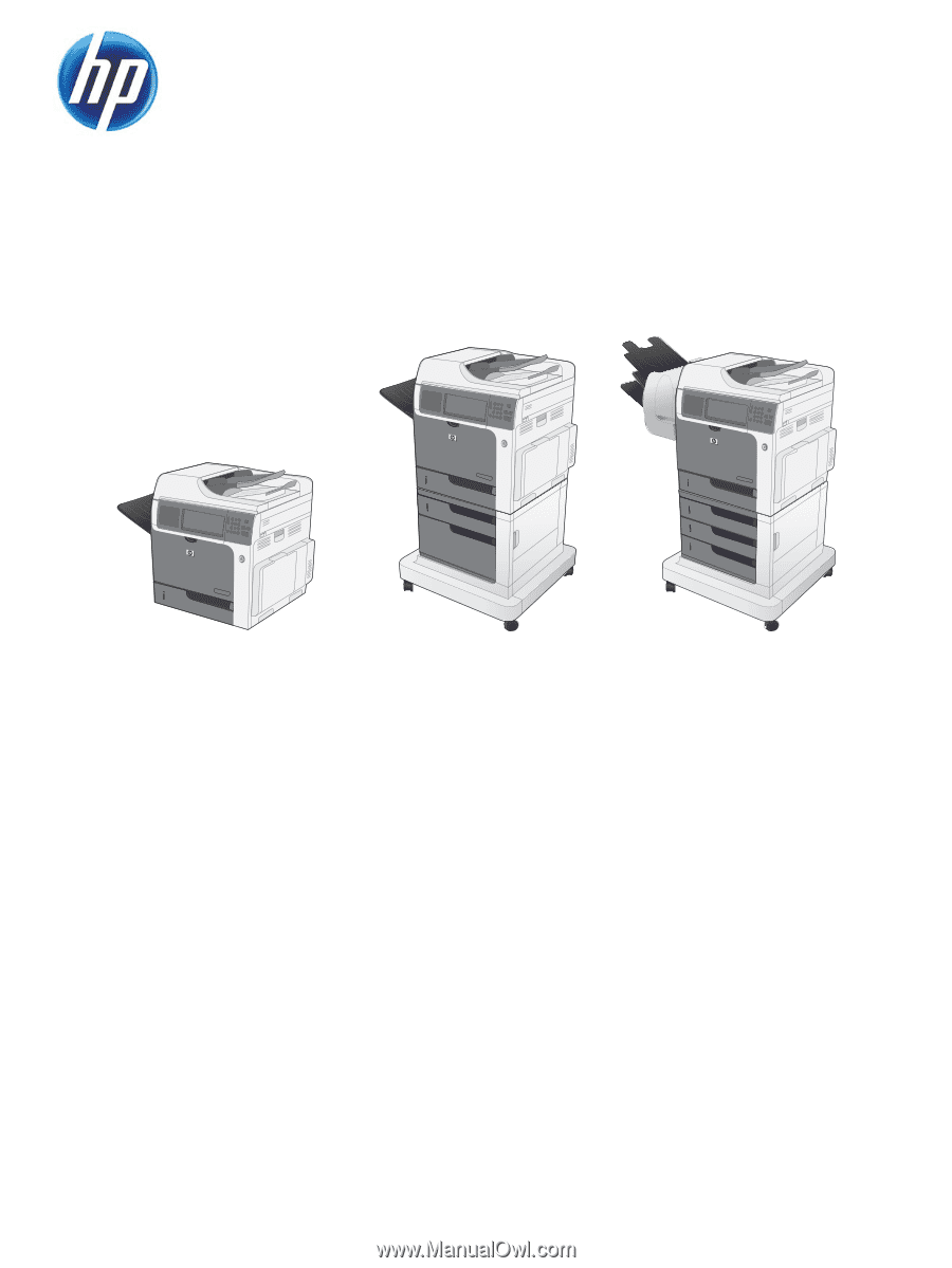
COLOR LASERJET ENTERPRISE CM4540
MFP SERIES
Service Manual